
Related Manuals for Renesas ISL9241EVAL1Z


Summary of Contents for Renesas ISL9241EVAL1Z
- Page 1 ISL9241EVAL1Z User’s Manual: Evaluation Board Battery and Optical Rev.2.00 Oct 2018...
-
Page 2: Key Features
The ISL9241EVAL1Z evaluation board is designed to demonstrate the performance of the ISL9241. From the PROG pin to GND, the resistor can be used to program the default value numbers of the battery in series, the switching frequency, and the adapter current limit charging function. -
Page 3: Related Literature
OTGEN/CMIN PSYS BATGONE/NTC PSYS Figure 1. ISL9241EVAL1Z Block Diagram Recommended Equipment • 0V to 25V power supply with at least 6A source current capability • Electronic load capable of sinking current up to 6A • Battery emulator capable of sinking and sourcing current up to 6A •... - Page 4 Graphical User Interface (GUI). The GUI facilitates access to the ISL9241 SMBus registers. This section describes how to install, start, and use the GUI. Required Hardware • ISL9241EVAL1Z evaluation board • USB 2.0 A/B cable Required Software The software Installation Wizard package includes all three required components: •...
-
Page 5: Installing The Usb Driver
ISL9241EVAL1Z 2. Installing the ISL9241 Software (a) The window shown in Figure 3 appears. Click Next. Figure 3. ISL9241 Control Software Installer (4) Follow the instructions to accept the two End User License Agreements to complete the software installation. (5) Click Close Menu from the installation wizard. - Page 6 ISL9241EVAL1Z 2. Installing the ISL9241 Software The message in Figure 5 appears when the driver is successfully installed. Figure 5. ISL9241 Successful Driver Installation (4) If the installation fails the Digital Signature required in Windows 10 or security settings, complete the following steps to bypass it.
-
Page 7: Using The Gui
The ISL9241 SMBus Control Tool Software must be installed to use the evaluation system. Do not connect the ISL9241EVAL1Z evaluation board to the USB port until installation is complete. Connect the ISL9241EVAL1Z to a power supply before using the SMBus GUI. Setting the USB Connection Connect the USB cable from the computer’s USB port to connector J... - Page 8 (2) Check the USB cable connections from the ISL9241EVAL1Z to the USB port of the computer. (3) Try different sequences: plug in the ISL9241EVAL1Z first or start the GUI first. If the problem continues, the USB driver may not be properly installed; therefore, the ISL9241EVAL1Z is not recognized. Refer to “Installing the USB Driver”...
-
Page 9: Functional Description
The ISL9241EVAL1Z evaluation board provides all circuits required to evaluate the features of the ISL9241. A majority of the features of the ISL9241 are available on the ISL9241EVAL1Z, such as adjustable output voltage, On-the-Go (OTG) mode, Trickle Charging mode for a depleted battery, and system power monitor at Buck, Boost, and Buck-Boost modes. - Page 10 (+) DMM Lead (-) Supply Lead (-) DMM Lead (+) Battery Lead USB Port for SMBus (-) Battery Lead BATGONE LED 1 LED 2 LED 3 BGATE Figure 7. ISL9241EVAL1Z Connections UG184 Rev.2.00 Page 10 of 30 Oct 22, 2018...
- Page 11 ISL9241EVAL1Z 4. Functional Description Regulating System Voltage (1) Set the power supply to 5V. With the output disabled, connect the (+) end to J and the (-) end to J (2) Ensure jumpers JP , JP , and JP are shorted. SW and SW should switch to the low position.
- Page 12 (3) Connect the USB cable at the USB port for the SMBus. LED1, 2, and 3 all turn on. (4) Turn on the power supply; LED3 goes out. Turn on the battery emulator and open the Renesas ISL9241 GUI (Figure Figure 8.
- Page 13 ISL9241EVAL1Z 4. Functional Description Configuring the ISL9241EVAL1Z for Trickle Charging Mode (1) Complete steps 1 through 5 in “Configuring the ISL9142EVAL1Z for Charging Mode” without any changes. Set the MinSysVoltage register and the ChargeCurrentLimit register to non-zero values. (2) Decrease the battery emulator voltage and monitor the battery charging current. If the battery emulator voltage is less than 5.2V (lower than MinSysVoltage), the battery enters trickle Charging mode and the charge current...
- Page 14 (8) Increase the electrical load slowly and monitor the load voltage. If the load current is less than the OTGCurrent limit value, the load voltage is regulated at the setting value. Configuring the ISL9241EVAL1Z for Bypass Mode Refer to AN1994, “ISL9241 Operation Modes” for information about how to transition between different NVDC and Bypass modes.
-
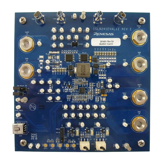
Page 15: Pcb Layout Guidelines
This section provides real examples of PCB layouts. The guidance is specific to board implementation, indicates key techniques used, and highlights areas that affect both functionality and performance. ISL9241EVAL1Z Evaluation Board Figure 11. ISL9241EVAL1Z Evaluation Board (Top) UG184 Rev.2.00 Page 15 of 30... - Page 16 ISL9241EVAL1Z 5. PCB Layout Guidelines Figure 12. ISL9241EVAL1Z Evaluation Board (Bottom) UG184 Rev.2.00 Page 16 of 30 Oct 22, 2018...
- Page 17 ISL9241EVAL1Z Schematic Optional - Additional short circuit protection FOR ISL9238, POPULATE COMPONENTS IN ORANGE FOR ISL9241, POPULATE COMPONENTS IN GREEN All NFETs and PFETs are 3x3 size When Bypass FETs are not populated, do not leave BYPSRC floating Connect it with 0 ohm resistor to VDD...
-
Page 18: Bill Of Materials
5. PCB Layout Guidelines Bill of Materials Reference Designator Description Manufacturer Manufacturer Part Number ISL9241EVAL1Z REVD PWB-PCB, ISL9241EVAL1Z, Imagineering ISL9241EVAL1Z REVC PCB REVD, ROHS IC-NOTEBOOK BATTERY Renesas ISL9241HRZ CHARGER, 32P, QFN, 4x4, ROHS CAP, SMD, 0603, 10pF, 50V, Kemet C0603C100K5GACTU... - Page 19 ISL9241EVAL1Z 5. PCB Layout Guidelines Reference Designator Description Manufacturer Manufacturer Part Number JP3, JP4, JP5, JP7 CONN-HEADER, 1x2, Berg/FCI 69190-202HLF RETENTIVE, 2.54mm, 0.230x 0.120, ROHS" JP3, JP4, JP6-Pins 1-2 CONN-JUMPER, SHORTING, Sullins SPC02SYAN 2PIN, BLACK, GOLD, ROHS DIODE-RECTIFIER, SMD, Diodes Incorporated...
- Page 20 Do Not Populate or Purchase Affix to Back of PCB LABEL-DATE CODE_LINE 1: Renesas LABEL-DATE CODE YRWK/REV#, LINE 2: BOM NAME Rename PCB to: LABEL, TO RENAME BOARD Renesas LABEL-RENAME BOARD ISL9241EVAL1Z REV E UG184 Rev.2.00 Page 20 of 30 Oct 22, 2018...
- Page 21 Layout Guidelines Bottom Connect this ground pad to the ground plane through a low impedance path. Renesas recommends using at least five vias to connect to ground planes in the PCB to ensure sufficient thermal dissipation directly under the IC.
- Page 22 ISL9241EVAL1Z 5. PCB Layout Guidelines Table 1. Guidelines for PCB Layout (Continued) Pin # Pin Name Layout Guidelines CSIN Run two dedicated traces with sufficient width in parallel (close to each other to minimize the loop area) from the two terminals of the adapter current-sensing resistor to the IC. Place the Differential mode and CSIP common-mode RC filter components in the general proximity of the controller.
-
Page 23: Board Layout
ISL9241EVAL1Z 5. PCB Layout Guidelines Board Layout Figure 14. Silkscreen Top Layer Figure 15. Inner Layer 1 UG184 Rev.2.00 Page 23 of 30 Oct 22, 2018... - Page 24 ISL9241EVAL1Z 5. PCB Layout Guidelines Figure 16. Inner Layer 2 Figure 17. Bottom Layer (Mirror Image) UG184 Rev.2.00 Page 24 of 30 Oct 22, 2018...
-
Page 25: Typical Performance Curves
ISL9241EVAL1Z 6. Typical Performance Curves Typical Performance Curves Figure 18. Boost Mode, output voltage loop to adapter Figure 19. Boost Mode, charge current loop to adapter current loop transition, V = 5V, V = 11V, current loop transition, V = 5V, V = 11V, MaxsystemVoltage = 12.576V,... - Page 26 ISL9241EVAL1Z 6. Typical Performance Curves Figure 22. Buck Mode, output voltage loop to adapter Figure 23. Buck Mode, charge current loop to adapter current loop transition, V = 20V, V = 11V, current loop transition, V = 20V, V = 11V, MaxsystemVoltage = 12.576V,...
- Page 27 ISL9241EVAL1Z 6. Typical Performance Curves Figure 26. OTG mode enable using OTGEN pin. Figure 27. OTG mode transient. V = 11V,V = 5V, = 11V, V = 5V, general purpose comparator load = 0.5A to 2A disabled, OTGEN Control bit enabled Figure 28.
-
Page 28: Revision History
ISL9241EVAL1Z 7. Revision History Revision History Rev. Date Description 2.00 Oct 22, 2018 Updated schematic. 1.00 Oct 11, 2018 Added schematic on page 17. Added Bill of Materials starting on page 18. Added Typical Performance Curves starting on page 25. - Page 29 10. It is the responsibility of the buyer or distributor of Renesas Electronics products, or any other party who distributes, disposes of, or otherwise sells or transfers the product to a third party, to notify such third party in advance of the contents and conditions set forth in this document.
- Page 30 ISL9241EVAL1Z UG184...
- Page 31 Mouser Electronics Authorized Distributor Click to View Pricing, Inventory, Delivery & Lifecycle Information: Renesas Electronics ISL9241EVAL1Z...
Need help?
Do you have a question about the ISL9241EVAL1Z and is the answer not in the manual?
Questions and answers