Table of Contents
Advertisement
Quick Links
User Manual
ISL94216EVKIT1Z
Evaluation Kit and GUI
This user manual demonstrates basic operations of the GUI and ISL94216 Evaluation Kit. Use this document in
the sequence it was written, each section assumes the previous section was completed. See the
ISL94216
datasheet for detailed information.
Software
The ISL94216 Evaluation Board GUI Code zip file must be downloaded from the Documentation and Downloads
section of the
ISL94216EVKIT1Z
board page. The ISL94216 GUI is built on top of Excel using Visual Basic for
Applications (VBA 1.00). It is designed to allow you to perform detailed evaluation of the ISL94216 and also
includes a simplified demonstration GUI.
Hardware
The ISL94216 Evaluation Kit consists of the following components:
• ISL94216EV1Z - ISL94216 evaluation board
• ISO-DONGLE-EV1Z - ISL94216 communications dongle with USB cable
• BMS-PS-CELL16Z - A 16-cell resistor ladder board
The following equipment is also needed to complete an evaluation of the device:
• Power supply (or battery pack)
• Current meter
• Voltmeter
• Oscilloscope
Ordering Information
Part Number
Description
ISL94216EVKIT1Z
ISL94216 evaluation kit
R16US0006EU0201 Rev.2.1
Page 1 of 49
Jun 16, 2021
Advertisement
Table of Contents

Related Manuals for Renesas ISL94216EV1Z


Summary of Contents for Renesas ISL94216EV1Z
- Page 1 GUI. Hardware The ISL94216 Evaluation Kit consists of the following components: • ISL94216EV1Z - ISL94216 evaluation board • ISO-DONGLE-EV1Z - ISL94216 communications dongle with USB cable • BMS-PS-CELL16Z - A 16-cell resistor ladder board The following equipment is also needed to complete an evaluation of the device: •...
- Page 2 V2P5 BASE EMITTER CMS1 CMS0 MISO/SDA/ Single Wire PACK- EPAD MOSI THERM AUX1/XT1 ADDR /CS ALRT WAKEUP VTEMP RESET THERM AUX0/XT0 DGND Figure 1. ISL94216 Typical Application R16US0006EU0201 Rev.2.1 Page 2 of 49 Jun 16, 2021 © 2020 Renesas Electronics...
-
Page 3: Table Of Contents
Exiting the Demo GUI ............. 35 R16US0006EU0201 Rev.2.1 Page 3 of 49 Jun 16, 2021 © 2020 Renesas Electronics... - Page 4 Appendix A ................39 R16US0006EU0201 Rev.2.1 Page 4 of 49 Jun 16, 2021 © 2020 Renesas Electronics...
-
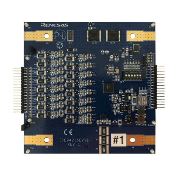
Page 5: Functional Description
2) as shipped from stock is set up for 16 cells with external cell balancing components selected to provide ~500mA of cell balancing current. Figure 2. ISL94216EV1Z Evaluation Board Supply current can be monitored by connecting the current meter across J9 or J10. These jumpers MUST be in place if a current meter is not. -
Page 6: Evaluation Board Leds
GUI does not connect to the device. With these switches in the up position the GUI can configure the dongle and ISL94216 to use any of the three available protocols after the connect function is complete. Figure 5. Communication Switches R16US0006EU0201 Rev.2.1 Page 6 of 49 Jun 16, 2021 © 2020 Renesas Electronics... -
Page 7: Communications Dongle
Each CELL of the resistor ladder consists of three 300Ω resistors in parallel resulting in 100Ω per cell. At a typical operating voltage of 48V with 16 100Ω cells in series ~30mA is consumed. R16US0006EU0201 Rev.2.1 Page 7 of 49 Jun 16, 2021 © 2020 Renesas Electronics... -
Page 8: Power Supply
The voltmeter is used to measure various voltages of interest on the ISL94216 BMS assembly. The recommended startup connection is Pack+ (J7) vs Pack- (J8). Oscilloscope For capture of communications, analog and digital signals associated with the ISL94216 as needed. R16US0006EU0201 Rev.2.1 Page 8 of 49 Jun 16, 2021 © 2020 Renesas Electronics... -
Page 9: Bms Assembly
J10 should be removed. This separates the voltage sense lines from the load/charge current path to reduce errors to a minimum and is the recommended configuration for all applications. R16US0006EU0201 Rev.2.1 Page 9 of 49 Jun 16, 2021 © 2020 Renesas Electronics... -
Page 10: Isl94216 Gui Start
Figure 11. GUI Start Press the Launch button to start the GUI. The first time the GUI is launched the Renesas Software License Agreement pop-up opens, select I accept the agreement and click Continue after reviewing it to start the GUI. -
Page 11: Power Supply
Click on the Read Settings button on the left side of the GUI to sync the information displayed in the GUI to the settings in the ISL94216. This button operates in all but SHIP Mode. R16US0006EU0201 Rev.2.1 Page 11 of 49 Jun 16, 2021 © 2020 Renesas Electronics... - Page 12 Figure 16. Main Display Following Execution of Basic Init Screen captures of Basic Init settings displayed in the tab panels can be found in “Appendix A” on page R16US0006EU0201 Rev.2.1 Page 12 of 49 Jun 16, 2021 © 2020 Renesas Electronics...
-
Page 13: Scan Mode
ALRT pin if Mask Register 0x65 Bit 0 is set to 0 (done by Basic Init). ALRT is low when the device is busy and transitions high when measurements complete. This bit combined with ALRT is useful for applications and bench debug. R16US0006EU0201 Rev.2.1 Page 13 of 49 Jun 16, 2021 © 2020 Renesas Electronics... -
Page 14: Single System Scans
Check the Scan before Read box then click the Read Measurement button (Figure 16) to trigger a single system scan and display the results of the measurements. The scope capture should look similar to the image in Figure R16US0006EU0201 Rev.2.1 Page 14 of 49 Jun 16, 2021 © 2020 Renesas Electronics... -
Page 15: Continuous System Scans
0x01 and set (check) Bit 0x01.1 Sys Select, then click on the Write button below it. Writing a value of 0x02 to register 0x01 stops the continuous scan. R16US0006EU0201 Rev.2.1 Page 15 of 49 Jun 16, 2021 © 2020 Renesas Electronics... -
Page 16: Low Power Timer
2-pin CS connector. This should only be done if no significant load is present. It might be necessary to set all S1 switches to OFF. R16US0006EU0201 Rev.2.1 Page 16 of 49 Jun 16, 2021 © 2020 Renesas Electronics... - Page 17 Click the Read Page button on the system tab and confirm the mode has switched to LOW PWR as shown in Figure 24 Figure 23. Power FETs Figure 24. Scan Operation R16US0006EU0201 Rev.2.1 Page 17 of 49 Jun 16, 2021 © 2020 Renesas Electronics...
-
Page 18: Idle Mode
Measurement and note that the LED on time has increased, indicating a longer measurement period. Figure 25. VCell Measure 4.1.1 Cell Select Cell Select register settings (Figure 26) are found on the System tab of the GUI. Figure 26. Cell Select R16US0006EU0201 Rev.2.1 Page 18 of 49 Jun 16, 2021 © 2020 Renesas Electronics... - Page 19 If in SCAN Mode the Power FETs have been disabled, but they remain on if in IDLE Mode or if no charge current is detected. Check the Pack+ voltage on the evaluation board with the multimeter to verify. Press the Read Pwr button in the PowerFets block. R16US0006EU0201 Rev.2.1 Page 19 of 49 Jun 16, 2021 © 2020 Renesas Electronics...
-
Page 20: Ipack Trigger
31) update. Change the Measure Averaging for IPack on the System tab, trigger another measurement and note the LED on time has increased indicating a longer measurement period. R16US0006EU0201 Rev.2.1 Page 20 of 49 Jun 16, 2021 © 2020 Renesas Electronics... - Page 21 33. Step up the IPack current/voltage followed by a Trigger and Read until the threshold is violated and the COCF Fault bit (0x63.4) sets. The COCF indicator becomes red as seen in Figure Figure 33. PowerFets Block Figure 34. COCF R16US0006EU0201 Rev.2.1 Page 21 of 49 Jun 16, 2021 © 2020 Renesas Electronics...
- Page 22 Execute Clear Fault and enable CFET and DFET. If previously cleared, enter 5 in the two DOC and COC boxes (Figure 38) and write them to their shared register (0x0D). R16US0006EU0201 Rev.2.1 Page 22 of 49 Jun 16, 2021 © 2020 Renesas Electronics...
-
Page 23: Vreg Trigger
DFET are turned off. If this occurs during a continuous system scan in SCAN Mode then scan is stopped. Set the 0x1C VCC Min Threshold to its minimum, execute Clear Fault and enable CFET and DFET. R16US0006EU0201 Rev.2.1 Page 23 of 49 Jun 16, 2021 © 2020 Renesas Electronics... - Page 24 Note: Bit 0x65.5 CP NRDY also sets. This occurs if the charge pump was enabled prior to the transition to LOW POWER Mode and was not triggered by the IREG2 fault. Figure 45. IREG2 Fault R16US0006EU0201 Rev.2.1 Page 24 of 49 Jun 16, 2021 © 2020 Renesas Electronics...
-
Page 25: Vbat/Itemp Triggers
SCAN Mode sets the Bit 0x65.6 VBUVF and shuts off the power FETs. On the Meas tab, select VBat from the drop-down list and then press Trigger Individual. Read Measurements and notice the VPack result updates. R16US0006EU0201 Rev.2.1 Page 25 of 49 Jun 16, 2021 © 2020 Renesas Electronics... - Page 26 ITemp value. Perform Write Thresh followed by a Read to confirm the setting. Trigger another internal temperature measurement, then Read Measurements and note the IOTW bit is set as seen in Figure R16US0006EU0201 Rev.2.1 Page 26 of 49 Jun 16, 2021 © 2020 Renesas Electronics...
-
Page 27: Comm Timeout
MCU. This check box is highlighted in Figure Put the device in IDLE Mode by selecting IDLE from the drop-down Mode menu on the System tab as shown in Figure R16US0006EU0201 Rev.2.1 Page 27 of 49 Jun 16, 2021 © 2020 Renesas Electronics... - Page 28 ALRT LED flashes approximately every 2s. Verify the Mode change by reading register 0x2E. Put the device in IDLE Mode by selecting it from the drop-down menu, then uncheck the Comm TO Enable box to disable the Timeout function. R16US0006EU0201 Rev.2.1 Page 28 of 49 Jun 16, 2021 © 2020 Renesas Electronics...
-
Page 29: Low Power Mode
The Weak regulator operates at ~2.3V and it excludes the external transistor. The Weak regulator is only intended to drive the ISL94216 with enough voltage/current to maintain the register settings and communications. The Weak regulator is not able to drive external circuitry. R16US0006EU0201 Rev.2.1 Page 29 of 49 Jun 16, 2021 © 2020 Renesas Electronics... -
Page 30: Ship Mode
Note the supply current. Disconnect the dongle from the evaluation board, do not execute any GUI functions with the dongle disconnected. Note the supply current again. Reconnect the dongle. R16US0006EU0201 Rev.2.1 Page 30 of 49 Jun 16, 2021 © 2020 Renesas Electronics... -
Page 31: Wakeup
Press the WAKEUP# button (NOT RESET#) on the evaluation board and then perform another Read Page on the system tab. Note the mode has returned to IDLE as seen in Figure Figure 58. Wake Up R16US0006EU0201 Rev.2.1 Page 31 of 49 Jun 16, 2021 © 2020 Renesas Electronics... -
Page 32: Demonstration Gui
After launching the demo GUI, press the Demo Init button on the left side of the GUI as highlighted in Figure This configures the ISL94216 with settings appropriate for demonstration, and reads these settings into the GUI. Figure 60. Demo GUI R16US0006EU0201 Rev.2.1 Page 32 of 49 Jun 16, 2021 © 2020 Renesas Electronics... -
Page 33: Demo Single Scan
The Graph displays information based on which option is selected in the Graph Type section. The VCell option displays the voltage of each cell, the temperature option shows both internal and auxiliary temperatures, and the R16US0006EU0201 Rev.2.1 Page 33 of 49 Jun 16, 2021 © 2020 Renesas Electronics... -
Page 34: Demo Threshold Modification
Figure 67, then press the Write Thresholds button. A single scan can be used to confirm the settings were written correctly. Figure 67. Demo Thresholds R16US0006EU0201 Rev.2.1 Page 34 of 49 Jun 16, 2021 © 2020 Renesas Electronics... -
Page 35: Demo Fault Indicators/Clearing
To return to the evaluation GUI from the demonstration GUI simply press the Exit Demo button in the top left corner of the display. This button is highlighted in Figure Figure 69. Exit Demo R16US0006EU0201 Rev.2.1 Page 35 of 49 Jun 16, 2021 © 2020 Renesas Electronics... - Page 36 Schematic Figure 70. Eval Board Schematic Sheet 1...
- Page 37 Figure 71. Eval Board Schematic Sheet 2...
- Page 38 Corrected typos and added clarifications. Added Evaluation Board Communications Switches section. Updated Figures 7 through 10, 70, and 71. Moved Appendix to the correct location. Jun 3, 2020 Initial release R16US0006EU0201 Rev.2.1 Page 38 of 49 Jun 16, 2021 © 2020 Renesas Electronics...
- Page 39 73) can be found in the excel workbook that contains the GUI. These sheets allow you to save and access multiple complete device configurations and switch between them quickly. Figure 73. Configuration Tabs R16US0006EU0201 Rev.2.1 Page 39 of 49 Jun 16, 2021 © 2020 Renesas Electronics...
- Page 40 The IPack current is calculated by dividing the IPack voltage by the RSense resistor value stored on the IPack tab. The IReg current is calculated by dividing the IReg voltage by the IReg Sense R resistor value on the ITemp/Reg tab. R16US0006EU0201 Rev.2.1 Page 40 of 49 Jun 16, 2021 © 2020 Renesas Electronics...
- Page 41 Scan and Global operations registers, which measurements are enabled during a scan, Low Power Mode Options, Measure Averaging Options, and how frequently certain values are updated during a continuous scan. R16US0006EU0201 Rev.2.1 Page 41 of 49 Jun 16, 2021 © 2020 Renesas Electronics...
- Page 42 When VCell Connect is enabled, it allows detections of OVF, UVF, and DVCF to turn off the Power FETs. DCHRWOV allows discharging while a cell overvoltage condition is present and CHRWUV allows charging while a cell undervoltage condition is present. R16US0006EU0201 Rev.2.1 Page 42 of 49 Jun 16, 2021 © 2020 Renesas Electronics...
- Page 43 Importantly, this is where you can set the RSense value that the GUI uses to calculate the current displayed on the Meas tab. Press Write Thresh to move the new values into the device after changing them on the GUI. R16US0006EU0201 Rev.2.1 Page 43 of 49 Jun 16, 2021 © 2020 Renesas Electronics...
- Page 44 Meas tab. Press Write Thresh to store the value after changing it. This resistor is 3.3Ω on stock RevC EVKITs. Check R15 on the evaluation board to be certain, it is nearest to the lower right corner of the ISL94216. R16US0006EU0201 Rev.2.1 Page 44 of 49 Jun 16, 2021 © 2020 Renesas Electronics...
- Page 45 The Thresholds sub-tab (Figure 80) allows you to view and modify various auxiliary related fault settings. Aux Connect controls if an Aux related fault disables the power FETs. R16US0006EU0201 Rev.2.1 Page 45 of 49 Jun 16, 2021 © 2020 Renesas Electronics...
- Page 46 82) allows you to view and adjust various cell balancing and charging related thresholds. There is also a charging profile that provides insight into what each of these thresholds represents. R16US0006EU0201 Rev.2.1 Page 46 of 49 Jun 16, 2021 © 2020 Renesas Electronics...
- Page 47 The tab also allows you to select from the various GPIO configurations for the device. See the datasheet for the various GPIO configurations and operation. R16US0006EU0201 Rev.2.1 Page 47 of 49 Jun 16, 2021 © 2020 Renesas Electronics...
- Page 48 85) allows you to view and modify the various mask bits in the device. Writing any of these bits to 0 allows the corresponding fault/status to propagate to the ALRT pin. R16US0006EU0201 Rev.2.1 Page 48 of 49 Jun 16, 2021 © 2020 Renesas Electronics...
- Page 49 ISL94216EVKIT1Z 9. Revision History Figure 86. Dongle Tab The Dongle tab (Figure 86) allows you to view and modify the settings of the ISO-DONGLE-EV1Z communications dongle. R16US0006EU0201 Rev.2.1 Page 49 of 49 Jun 16, 2021 © 2020 Renesas Electronics...
- Page 50 Renesas' products are provided only subject to Renesas' Terms and Conditions of Sale or other applicable terms agreed to in writing. No use of any Renesas resources expands or otherwise alters any applicable warranties or warranty disclaimers for these products.
- Page 51 Mouser Electronics Authorized Distributor Click to View Pricing, Inventory, Delivery & Lifecycle Information: Renesas Electronics ISL94216EVKIT1Z...
Need help?
Do you have a question about the ISL94216EV1Z and is the answer not in the manual?
Questions and answers