Advertisement
ISL97519AIUZEVALZ
Description
The ISL97519AIUZEVALZ evaluation board is an evaluation kit
for evaluating the ISL97519AIUZEVALZ, a step-up voltage
regulator that operates with high frequency and high
efficiency. This evaluation kit is designed to deliver over 90%
efficiency.
The ISL97519AIUZEVALZ kit provides a dip switch that allows
users to select either 600kHz or 1.2MHz switching frequency.
Key Features
• A Complete Evaluation Platform for Evaluation of ISL97519A
• Input Voltage: 2.3V to 5.5V
• Proven Evaluation Board Layout
• Pb-free (RoHS Compliant)
Pin Configuration
ISL97519A
(8 LD MSOP)
TOP VIEW
COMP
1
FB
2
EN
3
GND
4
Ordering Information
PART #
ISL97519AIUZEVALZ
AN1645 Rev.1.00
Mar 3, 2022
8
SS
7
FSEL
VDD
6
5
LX
DESCRIPTION
Evaluation Board for ISL97519A
USER'S MANUAL
Quick Setup Guide
Step 1: Connect the power supply between the headers of VIN
and GND. The positive output of the power supply
should be connected to the VIN header. Set the power
supply voltage between 2.3V and 5V, and the current
limit at 3A.
Step 2: Connect the E-load between the headers of VOUT and
GND. The positive input of the E-load should be
connected to the VOUT header. Set the E-load current.
The load current should not exceed the maximum
output current that the part can supply.
Step 3: Close pins 1 and 4 of S1 to tie the FSEL pin to VIN. This
will set the switching frequency to 1.2MHz. Open pins
1 and 4 to pull FSEL to ground with R4 to set the
frequency to 600kHz.
Step 4: Close pins 2 and 3 of S1 to tie the EN pin to VIN in order
to enable the part. To disable the part, open pins 2 and
3 in order to pull EN to ground with R3 to disable the
part.
Make sure all the connections on the evaluation board are
correct, then turn on the power supply and E-load. The part will
start to operate.
Maximum Output Current
The MOSFET current limit is normally 2.0A and guaranteed at
1.7A. This restricts the maximum output current that the
ISL97519A can drive. Table 1 shows the ISL97519AIUZEVALZ
maximum output current, I
OMAX
voltages.
TABLE 1. TYPICAL MAXIMUM OUTPUT CURRENT
V
V
IN
OUT
(V)
(V)
2.5
5
2.5
9
2.5
12
3.3
5
3.3
9
3.3
12
5
9
5
12
© 2011-2022 Renesas Electronics
AN1645
Rev.1.00
Mar 3, 2022
at different input and output
I
OMAX
(mA)
870
500
380
1150
655
500
990
750
Page 1 of 6
Advertisement
Table of Contents

Subscribe to Our Youtube Channel
Related Manuals for Renesas ISL97519AIUZEVALZ


Summary of Contents for Renesas ISL97519AIUZEVALZ
- Page 1 2.3V and 5V, and the current efficiency. limit at 3A. The ISL97519AIUZEVALZ kit provides a dip switch that allows Step 2: Connect the E-load between the headers of VOUT and users to select either 600kHz or 1.2MHz switching frequency.
- Page 2 ISL97519AIUZEVALZ Board Design Schematic FIGURE 1. SCHEMATIC AN1645 Rev.1.00 Page 2 of 6 Mar 3, 2022...
-
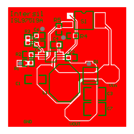
Page 3: Evaluation Board Layout
ISL97519AIUZEVALZ Evaluation Board Layout FIGURE 2. EVB ASSEMBLY LAYER AN1645 Rev.1.00 Page 3 of 6 Mar 3, 2022... - Page 4 ISL97519AIUZEVALZ Evaluation Board Layout (Continued) FIGURE 3. TOP LAYER AN1645 Rev.1.00 Page 4 of 6 Mar 3, 2022...
- Page 5 ISL97519AIUZEVALZ Evaluation Board Layout (Continued) FIGURE 4. BOTTOM LAYER AN1645 Rev.1.00 Page 5 of 6 Mar 3, 2022...
-
Page 6: Revision History
ISL97519AIUZEVALZ TABLE 2. ISL97519AIUZEVALZ BILL OF MATERIALS (BOM) ITEM REFERENCE PART DESCRIPTION PCB FOOTPRINT PART NUMBER VENDOR 27nF 4700nF 0.1µF/16V C1068X7R1H104K 86.6k WALSIN R2, R4, R5 WR06W1002JTL WALSIN 22µF 1206 MURATA 22µF 1206 GRM31CR61C226KE15L MURATA 10µF CDRH8D43 CDRH8D43NP-100NC SUMIDA ISL97519A... -
Page 7: Corporate Headquarters
Renesas' products are provided only subject to Renesas' Terms and Conditions of Sale or other applicable terms agreed to in writing. No use of any Renesas resources expands or otherwise alters any applicable warranties or warranty disclaimers for these products.
Need help?
Do you have a question about the ISL97519AIUZEVALZ and is the answer not in the manual?
Questions and answers