Table of Contents
Advertisement
Quick Links
ISL94216EVKIT1Z
Battery and Optical
All information contained in these materials, including products and product specifications,
represents information on the product at the time of publication and is subject to change by
Renesas Electronics Corp. without notice. Please review the latest information published by
Renesas Electronics Corp. through various means, including the Renesas Electronics Corp.
website (http://www.renesas.com).
Renesas Electronics Corporation
www.renesas.com
User's Manual: Evaluation Kit and GUI
Rev.1.00
Jun.3.20
Advertisement
Table of Contents

Related Manuals for Renesas ISL94216EVKIT1Z


Summary of Contents for Renesas ISL94216EVKIT1Z
- Page 1 All information contained in these materials, including products and product specifications, represents information on the product at the time of publication and is subject to change by Renesas Electronics Corp. without notice. Please review the latest information published by Renesas Electronics Corp. through various means, including the Renesas Electronics Corp.
- Page 2 ISL94216 and also includes a simplified demonstration GUI. Hardware The ISL94216EVKIT1Z evaluation kit consists of the following components: • ISL94216EV1Z - ISL94216 evaluation board • ISO-DONGLE-EV1Z - ISL94216 communications dongle with USB cable •...
- Page 3 ISL94216EVKIT1Z PACK+ VBAT1 VBAT2 VCPMP CFET DFET LDMON VC16 GPIO3 CB16 VC15 CB15 GPIO0 ISL94216 V2P5 BASE EMITTER CMS1 CMS0 MISO/SDA/ Single Wire PACK- EPAD MOSI THERM AUX1/XT1 ADDR/CS ALRT VTEMP WAKEUP RESET THERM AUX0/XT0 DGND Figure 1. ISL94216 Typical Application R16US0006EU0100 Rev.1.00...
-
Page 4: Table Of Contents
ISL94216EVKIT1Z Contents Functional Description ............. . . 6 Evaluation Board . - Page 5 ISL94216EVKIT1Z Appendix A ............... . 37 Schematic .
-
Page 6: Functional Description
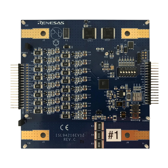
ISL94216EVKIT1Z 1. Functional Description Functional Description Evaluation Board Figure 2. ISL94216EV1Z Evaluation Board The ISL94216 evaluation board (Figure 2) as shipped from stock is set up for 16 cells with external cell balancing components selected to provide ~500mA of cell balancing current. -
Page 7: Evaluation Board Leds
ISL94216EVKIT1Z 1. Functional Description Figure 3. VC1 External Cell Balancing Circuitry The cell balancing current can be adjusted by changing resistors R34, R36, R38, R40, R42, R64, R66, R68, R70, R72, R94, R96, R98, R112, R114, and R116. VC1 external cell balancing circuitry is shown in... -
Page 8: Communications Dongle
ISL94216EVKIT1Z 1. Functional Description Communications Dongle Figure 5. ISO-DONGLE-EV1Z Communications Dongle The communications dongle, shown in Figure 5, is a board designed to isolate the ISL94216 evaluation board assembly ground from the PC and workbench grounds. Most Battery Management Systems (BMS) operate isolated from earth ground. -
Page 9: Power Supply
ISL94216EVKIT1Z 1. Functional Description Figure 6. Resistor Ladder Board Power Supply If a battery pack is not available, the combination of a power supply and a resistor ladder is used. The power supply must be selected so that it can supply the ladder, ISL94216 evaluation board, and load currents at the required voltage without current limiting. -
Page 10: Bms Assembly
ISL94216EVKIT1Z 1. Functional Description BMS Assembly The three boards described previously are connected together as shown in Figure Figure 7. BMS Assembly The resistor ladder and ISL94216 evaluation boards connectors line up Pin 1 to Pin 1 with a total of 17 pins. Pin 1... -
Page 11: Isl94216 Gui Start
ISL94216EVKIT1Z 2. ISL94216 GUI Start ISL94216 GUI Start Open the workbook to get started, there is no installation required. Macros are automatically disabled on some PCs; if the message SECURITY WARNING Macros have been disabled is visible beneath the menu bar, select Enable Content. -
Page 12: Initialization
ISL94216EVKIT1Z 2. ISL94216 GUI Start Figure 13. Connect The device must be powered for this step to complete successfully. If the device is not powered up, an error message is displayed informing you that there was a communication error. When this error occurs you should... - Page 13 ISL94216EVKIT1Z 2. ISL94216 GUI Start Figure 15. Main Display Following Execution of Basic Init Screen captures of Basic Init settings displayed in the tab panels can be found in “Appendix A” on page R16US0006EU0100 Rev.1.00 Page 13 of 51 Jun.3.20...
-
Page 14: Scan Mode
ISL94216EVKIT1Z 3. SCAN Mode SCAN Mode For normal operation during charging or discharging of the Battery Pack, the ISL94216 should be in SCAN Mode. The system Mode is controlled by the Scan Operation register, shown in Table 1 Table 2. The POR/RESET defaults are highlighted in yellow. -
Page 15: Single System Scans
ISL94216EVKIT1Z 3. SCAN Mode Single System Scans Select the check box for Bit 0 of the Global Operations register, then click on the Write button (Figure 17) to trigger a single system scan while watching ALRT LED D5. With Bits 0 and 1 selected, we are writing 0x03 to this register. -
Page 16: Continuous System Scans
ISL94216EVKIT1Z 3. SCAN Mode Figure 20. Oscilloscope Measurement Results Experiment by disabling all but one Measurement Enable bit to see the busy times for each section. Also, look at the effect on the measurement time of the averaging settings. The capture in... -
Page 17: Low Power Timer
ISL94216EVKIT1Z 3. SCAN Mode stop the scan, clear all bits of register 0x01 and set (check) Bit 0x01.1 Sys Select, then click on the Write button below it. Writing a value of 0x02 to register 0x01 stops the continuous scan. - Page 18 ISL94216EVKIT1Z 3. SCAN Mode jumper across the 2-pin CS connector. This should only be done if no significant load is present. It might be necessary to set all S1 switches to OFF. Set the Global Operations register to 0x01 to trigger a continuous system scan and watch the ALRT LED. After less than 60 seconds, the frequency of the LED flashing significantly decreases to ~2s as the device has transitioned from SCAN to LOW POWER Mode.
-
Page 19: Idle Mode
ISL94216EVKIT1Z 4. IDLE Mode IDLE Mode IDLE Mode is the default mode following POR, RESET, or Reset-to-IDLE. An Important difference between IDLE and SCAN Modes is neither continuous nor single system scans can be executed in IDLE Mode. Current direction bits CHRGI and DCHRGI do not operate in IDLE Mode, current direction dependent faults will set without regard to the current direction but the MCU is required to enable/disable CFET and DFET in IDLE Mode. - Page 20 ISL94216EVKIT1Z 4. IDLE Mode 4.1.1 Cell Select Cell Select register settings (Figure 25) are found on the System tab of the GUI. Figure 25. Cell Select The Cell Select register sets which and how many cells the ISL94216 manages. If the box (and associated bit) corresponding to a particular cell is 0 and grayed out, that cell is not measured or compared to thresholds.
-
Page 21: Ipack Trigger
ISL94216EVKIT1Z 4. IDLE Mode Figure 27. OV Fault If in SCAN Mode, the Power FETs have been disabled but they remain on if in IDLE Mode. Check the Pack+ voltage on the evaluation board with the multimeter to verify. Press the Read Pwr button in the PowerFets block. - Page 22 ISL94216EVKIT1Z 4. IDLE Mode 4.2.1 IPack Fault Detection IPack Fault detection threshold register settings (Figure 31) are found on IPack tab of the GUI. Figure 31. IPack Thresholds If using a battery pack, most cells are capable of providing the necessary current for the following examples.
- Page 23 ISL94216EVKIT1Z 4. IDLE Mode This fault is only detected during an IPack measurement, and when detected it shuts off the power FETs if the device is in SCAN Mode and Bit 0xE.2 COCF Connect is set as in Figure Execute Clear Fault and enable CFET and DFET using the methods previously described. Enter 5 in the two DOC...
-
Page 24: Vreg Trigger
ISL94216EVKIT1Z 4. IDLE Mode Figure 37. OC Delay Put the device in SCAN Mode, trigger a continuous system scan then count the times the ALRT LED flashes. With this setting five consecutive measurements above the threshold are required to trigger a fault, shut off the power FETs and stop system scan. - Page 25 ISL94216EVKIT1Z 4. IDLE Mode 4.3.2 IReg OC1 Threshold The Regulator Overcurrent 1 threshold register on the ITemp/Reg tab sets the maximum regulator current threshold when the device is in either SCAN or IDLE Mode. The threshold setting is compared to the voltage across the IREG sense resistor R15.
-
Page 26: Vbat/Itemp Triggers
ISL94216EVKIT1Z 4. IDLE Mode Put the device in IDLE Mode by selecting IDLE from the Mode drop-down menu on the System tab then press Read Page on the system tab to confirm the mode was switched successfully. The Bit 0x65.5 CP NRDY clears automatically, CFET and DFET turn back on but IREG2 remains set. - Page 27 ISL94216EVKIT1Z 4. IDLE Mode On the Voltage tab, adjust the value of 0x21 VBat1 UV Threshold to a voltage greater than the measured result. Then press Write Thresh to write the setting to the device, followed by a Read to confirm the setting was set properly.
-
Page 28: Comm Timeout
ISL94216EVKIT1Z 4. IDLE Mode Figure 49. IOTW This is intended as a warning bit, it does not shut off the power FETs or stop continuous system scans. 4.4.3.2 IOTF Threshold On the ITemp/Reg tab, set 0x23 IOTF Threshold to about 5° less than the ITemp display value then perform a Write Thresh followed by a Read to set and confirm the threshold. - Page 29 ISL94216EVKIT1Z 4. IDLE Mode Figure 51. Comm TO Figure 52. IDLE Mode After approximately 4s without communications the device transitions from IDLE to LOW POWER Mode. After this happens, the ALRT LED flashes approximately every 2s. Verify the Mode change by reading register 0x2E.
-
Page 30: Low Power Mode
ISL94216EVKIT1Z 5. LOW POWER Mode LOW POWER Mode Put the device in LOW POWER Mode by selecting LOW PWR from the Mode drop-down menu on the System tab as shown in Figure Figure 53. LP Mode As stated previously, while in this mode the ALRT LED flashes every ~2s while the ISL94216 powers up necessary circuitry to make measurements, then powers down again. -
Page 31: Ship Mode
ISL94216EVKIT1Z 6. SHIP Mode SHIP Mode Put the device in SHIP Mode by selecting SHIP from the Mode drop-down menu on the System tab as shown in Figure Figure 55. SHIP Mode Click on the Read Voltages button and note the results. While in SHIP Mode the IC does nothing but wait for a WAKEUP or a RESET assertion or a change mode command. - Page 32 ISL94216EVKIT1Z 6. SHIP Mode Figure 57. Wake Up R16US0006EU0100 Rev.1.00 Page 32 of 51 Jun.3.20...
-
Page 33: Demonstration Gui
ISL94216EVKIT1Z 7. Demonstration GUI Demonstration GUI Built into the full Evaluation GUI, there is also a demonstration GUI designed to highlight some of the key features and behaviors of the ISL94216. Launching the Demo GUI To launch the demo GUI, first press the green Connect button. If the device is not connected, the demo GUI does not launch and you are prompted with an error message. -
Page 34: Demo Continuous Scan
ISL94216EVKIT1Z 7. Demonstration GUI Figure 60. Single Scan Demo Continuous Scan The demo GUI also offers the ability to start and monitor a continuous scan in the ISL94216. To do this, press the Start Continuous Scan button, shown in Figure When the continuous scan has begun, the GUI updates approximately every two seconds with information from the previous scan. -
Page 35: Demo Threshold Modification
ISL94216EVKIT1Z 7. Demonstration GUI Figure 64. VCell Graph If you wish to look more closely at the data that is used to make the graphs, it can be seen on the Graph Sheet (Figure 65) of the GUI workbook. This data gets erased every time Start Graphing is pressed. -
Page 36: Demo Fault Indicators/Clearing
ISL94216EVKIT1Z 7. Demonstration GUI Demo Fault Indicators/Clearing The bottom left side of the screen provides fault indicators. If any of the faults listed are detected during a system scan, the corresponding fault box turns red. This can be seen in Figure 67 for VCell OV. - Page 37 ISL94216EVKIT1Z 8. Appendix A Appendix A The values displayed in the following images are the device settings following Basic Init. • The Reg Map tab (Figure 69) displays the values of all of the user registers in hex • The Read All Reg button reads the registers from the device and updates the GUI with these values.
- Page 38 ISL94216EVKIT1Z 8. Appendix A Figure 71. MEAS Tab The Meas tab (Figure 71) allows you to see the ISL94216 measurement results obtained during a system or an individual triggered scan. The IPack current is calculated by dividing the IPack voltage by the RSense resistor value stored on the IPack tab.
- Page 39 ISL94216EVKIT1Z 8. Appendix A Figure 72. System Tab The System tab (Figure 72) contains various settings related to overall system behavior. These include which cells are enabled, the Scan and Global operations registers, which measurements are enabled during a scan, Low Power Mode Options, Measure Averaging Options, and how frequently certain values are updated during a continuous scan.
- Page 40 ISL94216EVKIT1Z 8. Appendix A Figure 73. Voltage Tab The Voltage tab (Figure 73) allows you to view and change various thresholds and settings related to both Pack and Cell voltage settings. For VPack, you can set the Pack Overvoltage and Undervoltage fault thresholds, and VPack Connect allows you to control if these faults disable the power FETs.
- Page 41 ISL94216EVKIT1Z 8. Appendix A Figure 74. IPack Tab The IPack tab (Figure 74) contains various IPack control options. The IPack OC Thresholds section allows you to view and adjust settings related to charge overcurrent and discharge overcurrent conditions. The IPack, DSC, LDMON and WAKE UP Thresholds allow you to adjust other pack current and load detection related settings.
- Page 42 ISL94216EVKIT1Z 8. Appendix A Figure 75. ITEMP/Reg Tab The ITemp/Reg tab (Figure 75) allows you to view and modify settings related to the internal temperature fault thresholds and regulator thresholds. The IReg Sense R resistor value is set in this tab, which is used to calculate the IReg current value displayed on the Meas tab.
- Page 43 ISL94216EVKIT1Z 8. Appendix A Figure 76. AUX/AUX tab The Aux tab is composed of two sub-tabs related to the external thermistors. The Aux sub-tab (Figure 76) allows you to view and modify various component values related to the thermistors. Figure 77. AUX Thresholds Tab...
- Page 44 ISL94216EVKIT1Z 8. Appendix A Figure 78. CB Setup Tab The CB tab is composed of two Cell Balancing related sub-tabs. The Setup sub-tab (Figure 78) allows you to view and adjust various cell balancing related settings. Importantly, this is where the CB Operation register is controlled from. To understand how this register controls Cell Balancing consult the datasheet.
- Page 45 ISL94216EVKIT1Z 8. Appendix A Figure 80. GPIO Tab The GPIO tab (Figure 80) allows you to either view or control the status of the ISL94216 GPIO pins, depending on the configuration. The tab also allows you to select from the various GPIO configurations for the device. See the datasheet for the various GPIO configurations and operation.
- Page 46 ISL94216EVKIT1Z 8. Appendix A Figure 81. Faults/Status Bits Tab The Status tab is comprised of two sub-tabs. The Faults/Status Bits sub-tab (Figure 81) displays the status of the various faults and status bits contained in the ISL94216. Figure 82. Faults/Status Mask Bits Tab...
- Page 47 ISL94216EVKIT1Z 8. Appendix A Figure 83. Dongle Tab The Dongle tab (Figure 83) allows you to view and modify the settings of the ISO-DONGLE-EV1Z communications dongle. R16US0006EU0100 Rev.1.00 Page 47 of 51 Jun.3.20...
- Page 48 Schematic Figure 84. Evaluation Board Schematic Sheet 1...
- Page 49 Figure 85. Evaluation Board Schematic Sheet 2...
- Page 50 ISL94216EVKIT1Z 10. Revision History 10. Revision History Rev. Date Description 1.00 Jun.3.20 Initial release R16US0006EU0100 Rev.1.00 Page 50 of 51 Jun.3.20...
- Page 51 Renesas' products are provided only subject to Renesas' Terms and Conditions of Sale or other applicable terms agreed to in writing. No use of any Renesas resources expands or otherwise alters any applicable warranties or warranty disclaimers for these products.
- Page 52 ISL94216EVKIT1Z Renesas Electronics Corporation www.renesas.com R16US0006EU0100...
Need help?
Do you have a question about the ISL94216EVKIT1Z and is the answer not in the manual?
Questions and answers