Munters EC52 Manual For Use And Maintenance
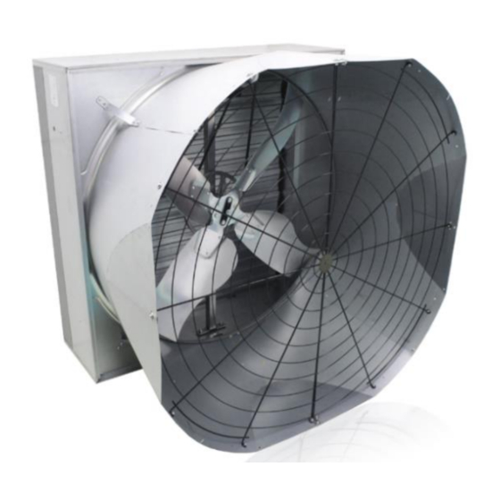
Air extraction fan, + ce declaration of conformity
Hide thumbs
Also See for EC52:
- Assembly manual (44 pages) ,
- Manual for use and maintenance (36 pages) ,
- Manual for use and maintenance (56 pages)

Subscribe to Our Youtube Channel
Related Manuals for Munters EC52


Summary of Contents for Munters EC52
- Page 1 EC52 Manual for use and maintenance + CE Declaration of conformity EC52 Air extraction fan Ag/MIT/ UmGB-2574-05/18 Rev 1.2...
- Page 2 Munters Italy S.p.A. reserves the right to effect modifications to the apparatus in accordance with technical and legal developments and to make alterations to specifications, quantities, etc.,for production or other reasons, subsequent to publication.
-
Page 3: Table Of Contents
7.1 Dimensions ....................32 7.2 Technical specifications .................32 8. MAINTENANCE ................... 34 8.1 Introduction ....................34 8.2 Routine Maintenance Program ..............34 8.3 Cleaning ......................34 8.4 Belt tensioning check up ................35 9. SPARE PART LIST ................36 Spare parts ......................41 © Munters AB, 2018... -
Page 4: Ce Declaration
UNI EN 953:2009, UNI EN ISO 12100:2010, UNI EN ISO 12499:2009, UNI EN ISO 13857:2008, CEI EN 60204-1:2006 (CEI 44-5), UNI EN ISO 5801:2009 Chiusavecchia, 17 May 2018 Massimo Colombo Legal Representative © Munters AB, 2018... -
Page 5: Disclaimer
Munters fans. 1.3 Notes Date of release: 2018. Munters cannot guarantee to inform users about the changes or to distribute new manuals to them. All rights reserved. No part of this manual may be reproduced in any manner whatsoever without the expressed written permission of Munters. -
Page 6: Data For Fan Eco Design Directive
1.4 Data for Fan Eco Design Directive Product information requirements → optional (according to ANNEX I -3.2 of regulation) Fan description EC52 2.0hp 3ph 37,2 static 41,9 no 1.827 30.164 81,1 458 50Hz OS EC52 1.5hp 3ph 33,9 static 39,1 no 1.546 30.377 62,1 438 50Hz OS EC52 1.0hp 3ph... -
Page 7: Safety Aspects
WARNING Unauthorized tampering/replacement of one or more parts of the machine, or the use of accessories, tools or materials other than those recommended by the manufacturer, are prohibited and release the manufacturer from all liability. © Munters AB, 2018... -
Page 8: General Safety Instructions
(emergency system activated and electricity and hydraulic fluid isolated). At the end of maintenance operations, the guards which were removed must be replaced correctly. © Munters AB, 2018... - Page 9 Dimensions and positioning accordance with Guard of fixed type made instructions in the standard Outlet side of fan of metal mesh. UNI EN 13857. Removable only by means of special tool. © Munters AB, 2018...
- Page 10 © Munters AB, 2018...
-
Page 11: Residual Risks
© Munters AB, 2018... - Page 12 Hazards generated by noise (measured at 2m distance) Fan model Sound pressure level Lp [dB(A)] 77.5 EC52 - 2 hp EC52 - 1.5 hp 77.1 EC52 - 1 hp 76.2 A measurement has been made of the noise produced by the machine during normal operation in order to calculate the equivalent level in conditions of normal use.
-
Page 13: Before Using
If yes restore them by mean of a screw-driver and re-check the opening of the shutter. Follow the steps shown in the pictures. fig.7 © Munters AB, 2018... -
Page 14: Structure
• fan housing in Munters Protect coated steel without welding spots; • fan shutter in Munters Protect coated steel, which pivots on UV protected plastic bushes and pins; • propeller with four blades in stainless or Munters Protect coated steel; blades are fixed to the propeller by high-strength pop rivets;... -
Page 15: Operating Conditions
• use by personnel not specifically trained; • installation of the fan for extraction or circulation under pressure; • use contrary to existing regulations; © Munters AB, 2018... - Page 16 EC declaration of conformity: it is up to the person responsible for the modification to resubmit the machine to the assessment conformity procedures specified in the applicable directives. © Munters AB, 2018...
- Page 17 (ammonia, clavulanic acid, etc.) the user, before installing the fan at the installation site must verify that the environmental conditions are compatible with the intended use of the materials that compose the fan. © Munters AB, 2018...
-
Page 18: Installation
The area adjacent to the fan in the premises from which air is being extracted must be kept clear to allow the air to exit freely. It is also prohibited for anyone to remain in this area, because of the presence of organic gases and dust which may be present in the airflow. © Munters AB, 2018... -
Page 19: Assembly Of The Cone
To move the cone to its working position, it is necessary to follow the steps indicated below. 1. Take two sectors of the cone, one for each type. fig.11 2. Align the four fingers of one of the two cone sectors respective slot of the other. fig.12 © Munters AB, 2018... - Page 20 5. Repeat from step 2, using the remaining two sectors, steering fingers same side. 6. Close cone steering fingers fig.14 internally. 7. Bolt the four junction points on the wide area of the cone fig.15 © Munters AB, 2018...
-
Page 21: Placement Of Fans
3-times fan diameter and the ingoing airflow must be kept free at least in a radius of 1.5 m distance in front of the fan. © Munters AB, 2018... - Page 22 Failure to install the safety mesh releases the manufacturer from all liability and shall be considered an improper use of the machine. © Munters AB, 2018...
-
Page 23: Connection To The Electrical System
IEC EN 60204-1 and IEC 60364. The electrical panel of the fan must generally be equipped with the following devices (bearing EC marking as per directive 2006/95/EC): Lockable isolating switch. fig.22 © Munters AB, 2018... - Page 24 Connection to the power supply must be done by means of a thermal overload protection switch, whose size depends on motor power. For safety reasons the overload switch can be locked by a padlock, not supplied by Munters. Electrical earthing must be carried out according to local regulations before the motor is connected to the supply voltage.
- Page 25 Failure to operate the fan with an overload protection device will render the motor guarantee null and void. Such motor overload protection devices can be ordered from Munters and be supplied with the fans. NOTE The connection cable must be completely extracted from the fan housing in order to avoid being damaged by moving parts.
- Page 26 50/60 2.8-2.4 / 1.1 single single 50/60 single 7.6-6.7 50/60 single 6.1-5.5 2 hp / 1.5 kW 50/60 single 3.5-3.2 single Standard fan motors have the following voltage and frequency: 230/400V three-phase 50 or 60 Hz. © Munters AB, 2018...
- Page 27 • check that the intensity of the short-circuit expected at the connection terminals is compatible with the breaking power of the protection switch upstream of the electrical panel; © Munters AB, 2018...
-
Page 28: Tests And Checks Before Startup
5.5 Tests and checks before startup Before startup, it is extremely important to carry out a very careful check of the fan, in order to prevent malfunctions and/or accidents. © Munters AB, 2018... - Page 29 The minimum frequency of operation of the engines in the case of absence of a forced external ventilation is 30 Hz. In the case of an operating frequency below 30 Hz is necessary to provide an external forced ventilation to the engine. © Munters AB, 2018...
-
Page 30: Commissioning
Interrupting the electricity supply, equivalent to isolating by the operator with the main switch, causes complete fan shutdown: restoring the electricity supply will not cause any movement in the machine. Emergency stop Operating the main emergency stop button causes the fan to stop moving. © Munters AB, 2018... - Page 31 After an emergency stop, the operating cycle must be reset by following the procedure described below: • reset the actuator by which the emergency stop command was given (by turning the relative mushroom button); • for an exact reset sequence, refer to the instructions given in section 6.2. © Munters AB, 2018...
-
Page 32: Technical Data
Airflow at 0 Pa /h [cfm] 42,200 [24,900] 47,570 [27,971] 49,500 [29,100] Airflow at 25 Pa /h [cfm] 35,100 [20,700] 41,792 [24,574] 44,700 [26,300] Airflow at 50 Pa /h [cfm] 26,200 [15,400] 33,074 [19,448] 36,400 [21,400] © Munters AB, 2018... - Page 33 Max. operating temperature °C [°F] 40 [104] Max. operating pressure [Pa] Nominal propeller speed [rpm] IEC protective class of electric motor IP55 Electric motor winding insulation grade *Excludes safety kit for installation below 2.7m above the floor. © Munters AB, 2018...
-
Page 34: Maintenance
8.2 Routine Maintenance Program Following the maintenance program prepared by our experts is the best way to ensure the smooth operation of Munters fans, to improve their performance and to give a longer lifespan. ROUTINE MAINTENANCE 1 MONTH 2 MONTHS 2 YEARS... -
Page 35: Belt Tensioning Check Up
In this particular event the manufacturer refuses all responsibility on consequent damages caused to things and people and considers any kind of warranty lost. © Munters AB, 2018... -
Page 36: Spare Part List
9. SPARE PART LIST DETAIL A © Munters AB, 2018... - Page 37 © Munters AB, 2018...
- Page 38 DETAIL A © Munters AB, 2018...
- Page 39 DETAIL B DETAIL C DETAIL D: ALIGNEMENT OF SHUTTER BLADE © Munters AB, 2018...
- Page 40 POSITIONING OF FRONT FLANGE ALIGNEMENT OF WATERPROOF DISTANCE PIECE FOR REAR FLANGE © Munters AB, 2018...
-
Page 41: Spare Parts
PLASTIC TIE ROD 2282052 CENTRAL PLASTIC BEARING RIGHT 2524501 PLASTIC BEARING RIGHT 2524101 SHUTTER BLADE 2439020 PLASTIC BEARING LEFT 2524301 METAL CLIP FOR MESH 2448600 Ø6,3×19 SELF-TAPPING SCREW 2278800 PYRAMIDAL SAFETY MESH 2823729 CENTRAL PLASTIC BEARING LEFT 2524701 © Munters AB, 2018... -
Page 42: Munters Ab
HEX SCREW M8X30 2281000 PLAIN WASHER D8X24 2276800 FRONT FLANGE W/ BUSHES 2252579 PROPELLER Zm120 2514497-K M8 HEX NUT 2273700 HEX NUT M6 WITH FLANGE 2282310 HUB WITH AXLE 2520330 M6×30 HEX SCREW 2279600 CENTRAL PULLEY 2248001 © Munters AB, 2018... - Page 43 2278400 M8X35 PLASTIC FORK 2265655 BRASS PIN 2249650 HEX NUT M6X5 2270700 HEXAGONAL AXLE 2252587 Ø6.4×12.5 POP UP RIVET S.S. 2272200 REINFORCING PLATE 2447140 PLAIN WASHER D10X40 2276010 * References change depending on the configuration utilized. © Munters AB, 2018...
- Page 44 MOTOR PULLEY PITCH DIAMETER / HOLE / V-BELT 3 PHASE - ONE SPEED 1 PHASE - ONE SPEED 50 Hz 60 Hz 50 Hz 60 Hz 1 hp 90/19/A75 75/19/A74 90/19/A75 75/19/A74 1.5 hp 100/24/A75 80/24/A74 100/24/A75 80/24/A74 2 hp 106/24/A75 90/24/A75 © Munters AB, 2018...
- Page 45 +90 262 7513 750, info@muntersform.com, Phone +1 517 676 7070, aghort.info@munters.com, Export & Other countries Phone +39 0183 5211, info@munters.it Munters reserves the right to make alterations to specifications, quantities, etc., for production or other reasons, subsequent to publication © Munters AB, 2018...
Need help?
Do you have a question about the EC52 and is the answer not in the manual?
Questions and answers