Advertisement
Quick Links
Instruction Manual
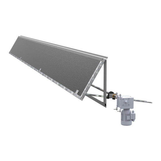
CSI24 Continuous Sidwall Inlet - Straight Rack
Room Side View
Horizon Series
CSI24 Continuous Sidewall Inlet
Models: CSI24100SF • CSI2410SF • CSI24100CF •
CSI2410CF
© Munters Corporation, August 2022
CSI24 Continuous Sidwall Inlet - Straight Rack
Outside/Hallway Side View
HORIZON
CSI24
Continuous
Sidewall Inlet -
Flush Mount
QM1217r0
1
Advertisement

Related Manuals for Munters Horizon Series


Summary of Contents for Munters Horizon Series
- Page 1 CSI24 Continuous Sidwall Inlet - Straight Rack Room Side View CSI24 Continuous Sidwall Inlet - Straight Rack Outside/Hallway Side View Horizon Series CSI24 Continuous Sidewall Inlet Models: CSI24100SF • CSI2410SF • CSI24100CF • CSI2410CF © Munters Corporation, August 2022 QM1217r0...
-
Page 2: Warranty
With the proper installation and maintenance it will provide many years of service. Please Note: To achieve maximum performance and insure long life from your Munters product it is essential that it be installed and maintained properly. Please read all instructions carefully before beginning installation. Warranty: For Warranty claims information see the “Warranty Claims and Return Policy”... - Page 3 2. Installation Instructions Framing Foam Seal Door Assembly Left Door Assembly Middle Door Assembly Right Door Assembly Door Installation Drive Frame Installation Actuator Installation 2.10 Drive Pipe Preperation 2.11 Drive Pipe Installation 3. Maintenance © Munters Corporation, August 2022 QM1217r0...
-
Page 4: Unpacking The Equipment
1.1 System Description The Munters CSI24 Continuous Sidewall Inlet is a 24"H. door that can be continuous for a total of 150'L. and can be mounted flush to the wall or offset so the drive pipe can be mounted away from the wall to avoid columns or posts. It can also use either Straight Racks or Curved Racks. - Page 5 ” Flat Washer, USS, ZP [10] AC3407 Inside Door Support, 24", GZ [11] AC3417 Outside Door Support, 24", GZ [12] AC3410 Rack Mounting Plate, GZ [13] AC3704 Guide Plate w/BRNZ Bushing, 1" Pipe, L, GZ © Munters Corporation, August 2022 QM1217r0...
- Page 6 ”-20 x 2.25” Carriage Bolt, ZP KN1709 ⁄ ”-16 Nylock Nut, ZP KS2282 #10-16 x ³⁄₄” HXWSR TEK Screw, SS KS2463 ⁄ ” x 1½ ” Lag Screw, ZP KS2466 ⁄ ” x 2” Lag Screw, ZP © Munters Corporation, August 2022 QM1217r0...
-
Page 7: Installation Instructions
LA actuator to. See Figure 1B . . C . 1 0 '- 0 " O 1 8 " Double 2x6 Treated 2 4 " 2x6 Treated 2x4 Treated Figure 1B HALLWAY SIDE 2 " © Munters Corporation, August 2022 QM1217r0... - Page 8 4" -- 6". See Figure 2A and 2B. 2x4 Framing Framing P-Shaped Foam Seal [4] Figure 2A P-Shaped Foam Seal [4] Staple or Nail (not provided) P-Shaped Foam Seal [4] Figure 2B © Munters Corporation, August 2022 QM1217r0...
- Page 9 (6) single holes in the middle area of the Door Edge Trim and the left most hole. See Figure 4. CSI24 Door with Hinge [1] Do not use this hole at this time. Door Edge Trim [2] TEK Screw [H] TEK Screw [H] location for Left End Door Figure 4 © Munters Corporation, August 2022 QM1217r0...
- Page 10 Support hangs off the end. See Figure 6. CSI24 Door with Hinge Outside Door Support [11] Left Pair of Holes TEK Screw [H] Rack Mounting Plate [12] Room Side shown for clarity TEK Screw [H] Figure 6 © Munters Corporation, August 2022 QM1217r0...
- Page 11 (2) Carriage Bolts [F] and Nylock Nuts [E], with the Nuts on the Pivoting Connector. See Figure 8. Carriage Bolt [F] Inside Door Support [10] Rack Mounting Plate [12] Pivoting Connector [9] Nylock Nut [E] Figure 8 © Munters Corporation, August 2022 QM1217r0...
- Page 12 Support hangs off the end. See Figure 10. CSI24 Door with Hinge Outside Door Support [11] Left Pair of Holes TEK Screw [H] Rack Mounting Plate [12] Room Side shown for clarity TEK Screw [H] Figure 10 © Munters Corporation, August 2022 QM1217r0...
- Page 13 (2) Carriage Bolts [F] and Nylock Nuts [E], with the Nuts on the Pivoting Connector. See Figure 12. Carriage Bolt [F] Inside Door Support [10] Rack Mounting Plate [12] Pivoting Connector [9] Nylock Nut [E] Figure 12 © Munters Corporation, August 2022 QM1217r0...
- Page 14 Slide a Door End Trim [15] over the Left Door and secure in place with (8) TEK Screws [H]. See Figure 14. CSI24 Door with Hinge [1] TEK Screw [H] Door End Trim [15] Figure 14 © Munters Corporation, August 2022 QM1217r0...
- Page 15 Make sure the holes go through the holes on one side of the door, through the holes on the other side. CSI24 Door with Hinge Rack Mounting Plate [12] Hole in Bracket Figure 16 © Munters Corporation, August 2022 QM1217r0...
- Page 16 (2) Carriage Bolts [F] and Nylock Nuts [E], with the Nuts on the Pivoting Connector. See Figure 17. CSI24 Door with Hinge Carriage Bolt [F] Rack Mounting Plate [12] Pivoting Connector [9] Pivoting Connector [9] Nylock Nut [E] Figure 17 © Munters Corporation, August 2022 QM1217r0...
- Page 17 Polebarn Screws [J]. The first screw should be 2" from the end and space the rest of the screws 4" apart. See Figure 18. Polebarn Screw [J] Framing Framing View from Hallway Left CSI24 Door Hinge Door Hinge Polebarn Screw [J] 2¹⁄₂" Polebarn Screw [J] CSI24 Door View from Room Figure 18 © Munters Corporation, August 2022 QM1217r0...
- Page 18 Inside Door support. Middle CSI24 Door Left CSI24 Door Round Hole in Bracket Square Hole in Bracket TEK Screw [H] Outside Door Support Figure 20 © Munters Corporation, August 2022 QM1217r0...
- Page 19 Framing by 2". If needed, the left end of the Right CSI24 Door may be trimmed to allow proper fit and overlap. See Figure 22. Right CSI24 Door End of Right Door to be Trimmed (if needed) Figure 22 © Munters Corporation, August 2022 QM1217r0...
- Page 20 Inside Door support. Right CSI24 Door Middle CSI24 Door Round Hole in Bracket Left Square Hole in Bracket CSI24 Door TEK Screw [J] Outside Door Support Figure 24 © Munters Corporation, August 2022 QM1217r0...
- Page 21 (6) TEK Screws [H]. Make sure the V-Notch in the Joiner Plate is aligned with the joint in the door and (3) TEK Screws [H] go into each door. See Figure 26. Joint Between Doors Flat Joiner Plate [6] TEK Screw [H] V-Notch in Joiner Plate Figure 26 © Munters Corporation, August 2022 QM1217r0...
- Page 22 Installation Instructions 2.8 Actuator Installation Step 29 Attach Actuator to actuator framing using (4) ⅜ " Lag Screws [L]. See Figure 27. Framing 9 " Actuator Framing ⅜ "Lag Screws [L] 2 " Figure 27 © Munters Corporation, August 2022 QM1217r0...
- Page 23 (2) holes are over the pipe. Then using these holes as a guide, drill (2) pilot holes through the pipe and then drill (2) ¹³⁄₃₂" dia. holes through the pipe. See Figure 29. Swedged End of Pipe 126"L. Drive Pipe [3] Straight Coupling [16] Figure 29 © Munters Corporation, August 2022 QM1217r0...
- Page 24 Each Pinion Gear will eventually line-up with each See Figure 31B. Door Support CHNL Bracket [6]. Pinion Gear [7] Set Screws [C] Figure 31A First Pre-Drilled Drive Pipe [3] Pinion Gear [7] with Set Screws [C] Figure 31B © Munters Corporation, August 2022 QM1217r0...
- Page 25 See Figure 33. Repeat this step for all but the last Drive Pipe [3]. Nut [G] Second Drive Pipe [3] with Pinion Gears First Drive Pipe [3] with Pinion Gears Bolt [D] Figure 33 © Munters Corporation, August 2022 QM1217r0...
- Page 26 Slide the Straight Coupling [17] over the end of the pipe near the Actuator and secure in place using (2) Bolts [D] and Nuts [G]. See Figure 35. Nut [G] Drive Pipe [3] Drive Pipe [3] Bolt [D] Figure 35 © Munters Corporation, August 2022 QM1217r0...
- Page 27 Figure 36 Step 39 Align each Pinion Gear with Set Screws with a Pivoting Connector on the Door below the Drive Pipe. See Figure 37. Pinion Gear with Set Screws Pivoting Connectors Figure 37 © Munters Corporation, August 2022 QM1217r0...
- Page 28 See Figure 39. If Curved Racks were purchased See Figure 40 on next page. Pivoting Connector [9] Hair Pin Cotter [B] Straight Rack [5] Clevis Pin [A] Plastic Retainer/Pinion Gear assembly Straight Rack [5] Figure 39 © Munters Corporation, August 2022 QM1217r0...
- Page 29 Before operating the system, use Tubes of Grease provided to lightly grease the Pinion Gear and the back of the Rack where it slides through the Black Plastic Retainer. See Actuator Manual for wiring instructions. © Munters Corporation, August 2022 QM1217r0...
-
Page 30: Maintenance
With power disconnected, inspect all electrical connections. Wiring should be secure and in good condition. Remove any dust build-up from control case and sensor using a soft brush or cloth. NEVER CLEAN ELECTRICAL EQUIPMENT WITH A PRESSURE WASHER! © Munters Corporation, August 2022 QM1217r0... - Page 31 This page left blank intentionally © Munters Corporation, August 2022 QM1217r0...
- Page 32 HORIZON CSI24 Door Off set Mount System is developed and produced by Munters Corporation, Lansing, Michigan U.S.A. 1-800-227-2376 Munters Europe AB, Isafjordsgatan 1, P.O. Box 1150, SE-164 26 Kista, Sweden. Phone +46 08 626 63 00, Fax +46 8 754 56 66.
Need help?
Do you have a question about the Horizon Series and is the answer not in the manual?
Questions and answers