
Related Manuals for OMP Hobby Decathalon 55 ARF


Summary of Contents for OMP Hobby Decathalon 55 ARF
- Page 1 I n s t a l l a t i o n Manual Decathalon 55 ARF Version Zhuhai Edge Smart Drive Technology Co., Ltd. www.omphobby.com...
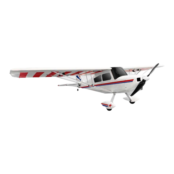
- Page 2 Parameter Specification Item: 55" Super Decathlon Color: ▢ White ▢ Green ▢ WingSpan: 1400mm(55in) Full Length: 1020mm(40in) Flight Weight: 1.55kg The Center of Gravity: Approx.70-75mm Wing Area: 34.67d㎡ Wing Load: 44.7g/d㎡ Wing Angle of Incidence: 1.5° Motor Thrust Angles: Down2.5°&Right 4° Pack Dimension 107*32*25 (L*H*W)cm Gross Weight: 7.35KG Servo: OMPHOBBY SG5 17g *4 : (Aileron*2,Elevator*1, Rudder*1) Electric Power (Recommended): Motor: Sunnysky 2820 , ESC: 40A, Propeller: Eolo 13x7E/12x6.5E, Lipo battery:3S/4S 2200-2600mah Recommended Settings of Dual Rates and Exponentials of Control Surfaces Low rate Low rate exp High rate High rate exp Aileron Elevator Rudder...
- Page 3 Ø Package contents (ARF version) Wings Assembly 1. Carefully locate the slots which has been made on aileron, lightly cut through the covering but not into the balsa sheeting; Insert 2mm inner hexagon screwdriver into the slots to make sure the glue inflow into the slots to secure the control arms. 2. Use sand paper to roughen the root of control arms. Try to insert it into the mounting slot to adjust the position at first, then take it out, apply glue to the slot and the root of the control arm insert it into the slot to secure it. ...
- Page 4 3. Pull out the white polyester thread from the servo holes with tweezers,tie up with the servo connector. 4. Find the other head of white polyester thread from wing side, pull it until servo is placed in servo hole. 5. Use screwdriver to tighten the screws to secure the servos. 6. Secure servo arms and control arms with ball head pull rod (After the glue is dried), put the cup head hexagonal screw, gasket, ball head on servo arm, secure it with iron pliers, adjust the ball head pull rods to proper length. 7. Secure screw, washer, ball head to control arm, check the degrees between servo arms and control arms. 8. Slide the left and right wings on to the carbon fiber wing tubes, and tighten the M5 nylon screws. Then, place the fuselage bottom up and remove the screws at the bottom of the wings. If necessary, gently bend the tips of the wing supports so the ends are flush with the respective screw holes on the wings and fuselage. Be sure to align the large wing supports towards the leading edge of the wings, and the smaller ones towards the trailing edges.
- Page 5 9. Make sure the two holes overlap with the claw holes, and then screw in the two‐wing support frame on the fuselage. (Note: Do not tighten each screw all at once. The screws at both ends of the wing support frame should be screwed into the threads and then tightened one by one.) 10. Pull up the stainless‐steel cable wing support frame on the wing, and then clamp the two black plastic pieces on the front and rear aluminum wing support frames. Then, adjust the aluminum wing support frame along the wing brace and the steel cable to make it straight. 11. I Insert the cable through the sleeve, and then thread the cable through the hole of the vertical stabilizer cable buckle, and then thread it back into the sleeve. After adjusting the tightness of the cable, use pliers to clamp the sleeve.
- Page 6 12. Repeat steps to affix the other end of the cable to the buckle on the same side horizontal stabilizer. Finally, cut off any excess cable. Then proceed to do the same on the other side. (Note: Do not over tighten the cable because it can cause the horizontal stabilizer to not be level and affect flight characteristics.) 13. Pass the remaining two cables through the sleeve, make a loop, and then thread them back into the sleeves while leaving a cable loop with a diameter of about 3mm. Then clamp the sleeve with pliers. Next, remove the second tail wheel screw. Align the cable loop holes of the two cables with the tail wheel screw hole, and then reinsert the screw back into the fuselage. Finally, fix the other end of the cable to the pull buckle on the same side horizontal stabilizer from previous steps. Be sure to cut off the excess cable.
- Page 7 14. Take out the 4 ball joint connecting rods, install 1 of the 58.5mm on the left as well as the right wing.Next, install the 60.5mm on the rudder, and the 90.5mm on the elevator. Elevator Assembly...
- Page 8 1. Take out the horizontal stabilizer and insert it face up into the slot in the tail of the fuselage, be sure to insert it fully. Insert the wing tubes into the front of the fuselage. Look forward from the rear of the fuselage to make sure that the horizontal stabilizer and wing tubes are parallel, and then use adequate glue on the gap to affix the horizontal stabilizer on the fuselage. 2. Carefully locate the slots which have been made on horizontal tail and vertical tail, lightly cut through the covering but not into the balsa sheeting; Insert 2mm inner hexagon screwdriver into the slots to make sure the glue inflow into the slot to secure the control arms. 3. Use sand paper to roughen the root of control arms. Try to insert it into the mounting slot to adjust the position at first, then take it out, apply glue to the slot and the root of the control arm, insert it into the slot to secure it. 4. Install elevator servos, assemble the servo arm and control arm with ball head pull rod, secure the cup head hexagonal screw, gasket, ball head to the servo arm, secure it with iron pliers, adjust the ball head pull rods to proper length. 5. Secure screw, washer, ball head to control arm. 6. The mounting locations of elevator servo and Ball head pull rod as in Figure. ...
- Page 9 Landing gear assembly 1. Take out the landing gear and related parts as below, install the wheels and wheel covers as shown, then, add a bit of blue thread lock screw glue to the tip of the screw. Then, align the holes of the landing gear with the holes of the fuselage, take out the wooden fittings and glue them to the landing gear, and then insert screws, be sure to tighten evenly. 2. Insert the rudder hinge into the slot of the vertical stabilizer, the bottom of the rudder and fuselage is kept flush, and there should be a gap of about 0.3mm (or about 4 sheets of printer paper thick) between the leading‐ edge ( L.E.) of the rudder and the trailing‐ edge ( T. E.) of the vertical stabilizer. Use appropriate glue to stick the hinge on the vertical stabilizer. After the glue is cured, take out the T2xl2mm Phillips self‐ tapping gasket screw, and pass it through the slot of the aluminum plate of the tail wheel. Screw it into the hole at the botton of the rudder.
- Page 10 Cowl and Engine Assembly Ø Motor Installation 1. Put the screws into motor mount and put aluminum columns to the other side of screws. 2. Apply glue to the screws and install motor to motor holder. Ø ESC Installation 1. Attach the connected ESC to ESC holder with double‐sided tape and Secure with cable ties. 2. Tie the wires of ESC and motor with fastening strap. 3. Connect the ESC and motor wires.
- Page 11 3. Tighten the propeller onto the motor shaft as shown in the figure. Make sure the spinner's back plate is flush with the propeller base. Add a little bit of blue thread lock to the tip of the screw, reinstall the spinner to the motor shaft, then tighten screw. Important note: A 6‐channel receiver is required / Navigation Lighting system: Designate a channel on the receiver as the lighting channel. u There is a designated air outlet pre‐cut into the balsa wood behind the bottom of the cowling on the bottom of the aircraft. To access, carefully cut the aircraft skin and balsa wood with a sharp blade. A hobby knife is recommended. Please refer to the picture below. Age Recommendation Not For Children Under 14 Years.this Is Not A Toy! :...
- Page 12 Guarantee The KAVAN Europe s.r.o. products are covered by a guarantee which fulfils the currently valid legal requirements in your country. If you wish to make a claim under guarantee, please contact the retailer from whom you first purchased the equipment. The guarantee does not cover faults which were caused in the following ways: crashes, improper use, incorrect connection, reversed polarity, maintenance work car- ried out late, incorrectly or not at all, or by unauthorised personnel, use of other than genuine KAVAN Europe s.r.o.
Need help?
Do you have a question about the Decathalon 55 ARF and is the answer not in the manual?
Questions and answers