Table of Contents
Advertisement
Quick Links
Advertisement
Table of Contents

Related Manuals for Akai MISTRAL912Dual-R32-K


Summary of Contents for Akai MISTRAL912Dual-R32-K
- Page 1 MODELS: MISTRAL912Dual-R32-K (Refrigerant R32)
-
Page 2: Table Of Contents
CONTENT 1. Summary and Features ................1 2. Safety Precautions ..................2 3. Specifications ....................4 3.1 Unit Specifications ..................... 4 3.2 Operation Characteristic Curve ................6 3.3 Capacity Variation Ratio According to Temperature ..........6 3.4 Noise Curve ........................ 7 4. -
Page 3: Summary And Features
Summary and Features 1. Summary and Features Outdoor Unit MISTRAL912Dual-R32-K SUV3-H24/3CGA-N... -
Page 4: Safety Precautions
Safety Precautions 2. Safety Precautions Installing, starting up, and servicing air conditioner can behazardous due to system pressure, electrical components, and equipment location, etc.Only trained, qualified installers and service personnel areallowed to install, start-up, and service this equipment.Untrained personnel can perform basic maintenance fun-ctions such as cleaning coils. All other operations should be performed by trained service personnel.When handling the equipment, observe precautions in themanual and on tags, stickers, and labels attached to theequipment. - Page 5 Safety Precautions Please read this operating manual carefully before operating the unit Appliance filled with flammable gas R32. Before use the appliance,read the ower's manual first. Before install the appliance,read the installation manual first. Before repair the appliance,read the service manual first. The figures in this manual may be diffrerent with the material objects, please refer to the material objects for reference .
-
Page 6: Specifications
Specifications 3. Specifications 3.1 Unit Specifications Model MISTRAL912Dual-R32-K - Product Code KEJ001W0170 - Cooling Capacity 5.20 Heating Capacity 5.20 3.71 4.16 SEER 6.10 SCOP(Average) 4.00 Energy Class A++/A+ Sound Pressure Level dB(A) Sound Power Level dB(A) Rated Voltage 220-240 Rated Frequency Phases Min/Max. - Page 7 Specifications Model SUV2-H18/1CFA-N SUV3-H24/3CGA-N Fan Type Axial-flow Axial-flow Fan Diameter-height 522-140 550-124 Fan Diameter-height inch 20.6-5.5 21.6-4.9 Motor Model SGW60M-ZL SGW120M-ZL Motor Type DC motor DC motor Motor Insulation Class Motor Safe Class IP44 IP44 Motor Full Load Amp(FLA) 1.03 0.96 Fan Motor Type DC motor...
-
Page 8: Operation Characteristic Curve
Specifications 3.2 Operation Characteristic Curve Cooling Heating Condition Condition Indoor:DB 20°C Indoor:DB 27°C WB19°C Indoor air flow: Super High Indoor air flow: Super High Pipe length:5m Pipe length:5m Voltage:230V Voltage:230V Compressor Speed(rps) Compressor Speed(rps) 3.3 Capacity Variation Ratio According to Temperature Heating operation ambient temperature range is -20ºC~24ºC Cooling Heating... -
Page 9: Noise Curve
Specifications 3.4 Noise Curve oise when blowing Outdoor side noise when blowing Super High High or rotating speed Compressor frequency(Hz) -
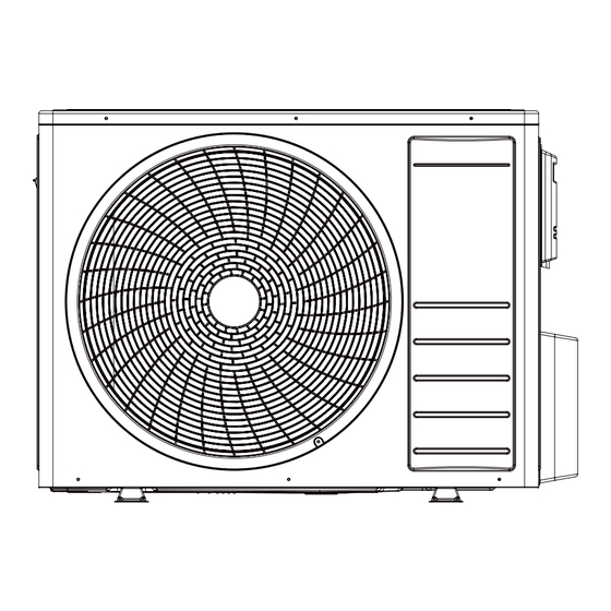
Page 10: Construction Views
Construction Views 4. Construction Views 4.1 Outdoor Unit MISTRAL912Dual-R32-K Unit:mm... - Page 11 Construction Views SUV3-H24/3CGA-N Unit:mm...
-
Page 12: Refrigerant System Diagram
Refrigerant System Diagram 5. Refrigerant System Diagram Heat Exchanger Filter Heat Exchanger Capillary Motor Electronic Expansion Valve Four-Way Valve Gas/Liquid Separator Compressor The outdoor and indoor units start to work once the power is switched on. During the cooling operation, the low temperature, low pressure refrigerant gas from the heat exchanger of each indoor unit gets together and then is taken into the compressor to be compressed into high temperature, high pressure gas, which will soon go to the heat exchanger of the outdoor unit to exchange heat with the outdoor air and then is turned into refrigerant liquid. - Page 13 Schematic Diagram MISTRAL912Dual-R32-K SUV3-H24/3CGA-N These circuit diagrams are subject to change without notice, please refer to the one supplied with the unit.
-
Page 14: Installation Manual
Installation Manual 7. Installation Instructions 7.1 Standard Accessory Parts The standard accessory parts listed below are furnished and should be used as required. Table 1 Name Appearance Q’ty Usage Drainage To connect with the hard PVC Connecter drain pipe Drain Plug To plug the unused drain hole One for 18K unit, Pipe Joint... -
Page 15: Safety Operation Of Flammable Refrigerant
Installation Manual 7.2 Safety operation of flammable refrigerant Qualification requirement for installation and maintenance man All the work men who are engaging in the refrigeration system should bear thevalid certification awarded by the authoritative organization and the qualification for dealing with the refrigeration system recognized by this industry. If it needs other technician to maintain and repair the appliance, they should be supervised by the person who bears the qualication for using the flammable refrigerant. - Page 16 Installation Manual Installation prepare To ensure the safety, please be mindful of the following precautions WARNING 1. When installing or relocating the unit, be sure to keep the refrigerant circuit free from air or substances other than the specified refrigerant. —...
-
Page 17: Installation Location And Matters Needing Attention
Table 3 Capacity of the Recommended Cord Models Power Supply Air Switch (pieces×sectional area) MISTRAL912Dual-R32-K 220-240V~,50Hz 3×1.5mm SUV3-H24/3CGA-N 220-240V~,50Hz 3×2.5mm... - Page 18 Installation Manual Notes: 1. The specifications of the breaker and power cable listed in the table above are determined based on the maximum power (maximum amps) of the unit. 2. The specifications of the power cable listed in the table above are applied to the conduit-guarded multi-wire copper cable (like, YJV copper cable, consisting of PE insulated wires and a PVC cable jacket) used at 40°C and resistible to 90°C (see IEC 60364-5-562).
- Page 19 Installation Manual ● Installation of the Outdoor Unit 1. During the transportation of the outdoor unit, two lifting ropes long enough must be used in four directions and the separation included angle must be less than 40° prevent the center of unit deviating. 2.
- Page 20 Installation Manual MISTRAL912Dual-R32-K OUTDOOR UNIT N(1) N(1) BN YEGN BN YEGN BN YEGN INDOOR UNIT 1 INDOOR UNIT 2 POWER SUV3-H24/3CGA-N OUTDOOR UNIT N(1) N(1) N(1) BN YEGN BN YEGN BN YEGN BN YEGN INDOOR UNIT 1 INDOOR UNIT 2...
- Page 21 Installation Manual Table 6 Dimension of the Refrigerant Pipe of the Indoor Unit Capacity Level of the Indoor Unit Gas Pipe (mm) Liquid pipe (mm) 07、09、12 Φ9.52 Φ6.35 Φ12.7 Φ6.35 ● Piping between the Indoor and Outdoor units 1. Refer to Table 7 for the moments of torque for tightening screws. 2.
- Page 22 ● Calculation of the Additional Refrigerant Charging 1. Refrigerant Charge in the Outdoor Unit before Shipment Table 8 Model Refrigerant Charge (kg) MISTRAL912Dual-R32-K 1.10 SUV3-H24/3CGA-N 1.50 Notes: (1). The refrigerant charge mentioned in the table above is not include those charged additionally in the indoor unit and the refrigerant pipe.
- Page 23 Installation Manual 3. Example: SUV3-H24/3CGA-N Fig.6 Table 10 Indoor Unit Serial No. Model Indoor Unit 1 SMVH09B-2A2A3NG(I) Indoor Unit 2 SMVH09B-2A2A3NG(I) Indoor Unit 3 SMVH09B-2A2A3NG(I) Table 11 Liquid Refrigerant Pipe Serial No. Diameter Φ6.35 Φ6.35 Φ6.35 Length The total length of each liquid refrigerant pipe is: a+b+c=20+15+15=50m Thus, the minimum additional refrigerant charge=(50-30)×0.016=0.32kg (Note: no additional refrigerant is needed for the liquid pipe within 30m) 4.
- Page 24 Installation Manual ● Items to be checked after the installation Table 14 Items to be Checked Possible Errors Check Results Has each part and component of the The unit may fall off ,vibrate or generate noise. unit been installed securely? The cooling (heating) capacity may Has the gas leakage test been taken? be poor.
-
Page 25: Test Operation
Installation Manual 7.4 Test operation 1. Preparation of test operation ● The client approves the air conditioner. ● Specify the important notes for air conditioner to the client. 2. Method of test operation ● Put through the power, press ON/OFF button on the remote controller to start operation. ●... -
Page 26: Exploded Views And Parts List
Exploded Views and Parts List 8. Exploded Views and Parts List 8.1 Outdoor Unit Model: MISTRAL912Dual-R32-K... - Page 27 Exploded Views and Parts List Part Code Description MISTRAL912Dual-R32-K Product Code KEJ001W0170 Grill(apricot grey) K21600002 Front panel(apricot grey) K11010002P K15010002 Fan motor K16800015 Motor support assembly K11200015 Left side panel(apricot grey) K10600005P Small handle K22210004 Chassis subassembly(apricot grey) K1040012102P Partition board subassembly...
- Page 28 Exploded Views and Parts List Model: SUV3-H24/3CGA-N...
- Page 29 Exploded Views and Parts List Part Code Description SUV3-H24/3CGA-N Product Code KEJ001W0180 Mesh enclosure(iresh) K10860013 Condenser assembly K20209112 Top cover(apricot grey) K10450023P Electric box assembly K39901161 Thermal package stents K20305018 Four way valve coil K3380000501 Motor support assembly K11200024 Suction pipe K20710111 Fan motor K16800024...
-
Page 30: Troubleshooting
Troubleshooting 9. Troubleshooting 9.1 PCB Printed Diagram Outdoor Unit(18K) ● Top View Silk scren name Connector Function note Connect compressorU(BU) connect blue U (BU) V (YE) W (RD) Compressor power line interface V (YE) connect yellow W(RD) connect red OUTFAN1 DC fan interface Connect outdoor DC fan P-SW... - Page 31 Troubleshooting Outdoor Unit(24K) ● Top View Silk scren name Connector Function note Connect compressorU(BU) connect blue U (BU) V (YE) W (RD) Compressor power line interface (YE) connect yellow W(RD) connect red P-SW Pressure switch interface Connect pressure switch (Reserve) Overload interface Connect compressor overload (Reserve) E l e c t r o n i c e x p a n s i o n v a l v e...
-
Page 32: Removal Procedure
Removal Procedure 10. Removal Procedure 10.1 Removal Procedure of Outdoor Unit(18K) Warning Be sure to wait for a minimum of 10 minutes after turning off all power supplies before disassembly. Procedure Note 1.Before disassembly 2. Remove top cover Top cover Screw Remove connection screws connecting the top cover plate with the front panel and the right side plate, and... - Page 33 Removal Procedure Procedure Note 4.Remove grille and panel A: Remove connection screws between the front grille and the front panel. Then remove the front grille. B: Remove connection screws connecting the front panel with the chassis and the motor support, and then remove the front panel. Front panel Grille 5.Remove axial flow blad and...
- Page 34 Removal Procedure Procedure Note 7. Remove left side plate Remove connection screws connecting the left side plate with the condenser assy. Then remove the left side plate. Left side plate 8. Remove right side plate Remove connection screws connecting the right Right side plate side plate with the valve support and the electric box.
- Page 35 Removal Procedure Procedure Note 10. Remove Reactor Take off the fixed scre,and you could take off the reactor. Reactor 11. Remove motor support Motor support Unscrewed the chassis and the motor bracket fixed screw, motor bracket is desirable. 12. Remove acoustic cotton Split the acoustic cotton lock,and take out 3 pcs slowly.
- Page 36 Removal Procedure Procedure Note 13. Remove 4-way valve assy Unsolder the spot weld of 4-way valve assy, compressor and condenser, and then remove the 4-way valve assy . 4-way valve assy Warning Discharge the refrigerant completely before unsoldering,when unsoldering, wrap the gas valve with awet cloth completely to avoid damage to thevalve caused by high temperature.
- Page 37 Removal Procedure Procedure Note 15. Remove Expansion valve Assy Unsolder the spot weld of expansion valve assy, liquid valve and condenser, and then remove the expansion valve assy . Expansion valve Assy 16. Remove the compressor A: Remove the 2 screws fixing the gas valve and unsolder the welding joint between the gas valve and the air-return pipe to remove the gas valve.
-
Page 38: Removal Procedure Of Outdoor Unit(24K)
Removal Procedure 10.2 Removal Procedure of Outdoor Unit(24K) Warning Be sure to wait for a minimum of 10 minutes after turning off all power supplies before disassembly. Procedure Note 1.Before disassembly 2. Remove top cover Top cover Remove connection screws connecting the top cover plate with the front panel and the right side plate, and then remove the toppanel. - Page 39 Removal Procedure Procedure Note 4.Open the side plate Use screwdriver unscrewed the fixed screw of the side plate and the chassis, and then descend into the handle of the side plate hole by hand press, make the side plate and on the right side of card board, panel button out, again ask outside, can remove the side plate.
- Page 40 Removal Procedure Procedure Note 7.Remove big handle and valve cover Big handle Remove the connection screw fixing the big handle and then remove the handle. Use a screwdriver to fixed valve cover screw drive, pull up to remove the valve cover. Valve cover 8.
- Page 41 Removal Procedure Procedure Note 10. Remove electric box assy Electric box assy Remove screws fixing the electric box assy; Screw loosen the wire bundle and unplug the wiring terminals. Then lift the electric box to remove it. 11. Remove Reactor Reactor Take off the fixed scre,and you could take off the reactor.
- Page 42 Removal Procedure Procedure Note 13. Remove acoustic cotton Split the acoustic cotton lock,and take out 3 pcs slowly. NOTE: Do not damage the pipe. Acoustic cotton 1 Acoustic cotton 2 Acoustic cotton 3 14. Remove 4-way valve assy 4-way valve assy Unsolder the spot weld of 4-way valve assy, compressor and condenser, and then remove the 4-way valve assy .
- Page 43 Removal Procedure Procedure Note 16. Remove Expansion valve Assy Expansion valve Assy Unsolder the spot weld of expansion valve assy, liquid valve and condenser, and then remove the expansion valve assy . 17. Split the valve and valve support Pull out the valve block with the hands or tools. Screwdriver unscrew the valve and valve bracket set screw, remove the air valve subassembly and hydraulic valve.
- Page 44 Per favore leggere e conservare queste istruzioni IMPORTER:BARNI CARLO S.P.A. ADDRESS:VIA ARCONATE 63, 20020 BUSTO GAROLFO (MILANO), ITALY www.akaielectronics.it...
Need help?
Do you have a question about the MISTRAL912Dual-R32-K and is the answer not in the manual?
Questions and answers