Advertisement
Reverse Cycle Inverter Air Conditioner
After Sales Support
1300 886 649 (AUS) 0800 836 761 (NZ) |
INSTALLATION MANUAL
Model Number
TAK-9000-25
TAK-12000-32
TAK-18000-50
TAK-24000-70
PROTECT YOUR WARRANTY
This unit must be installed by a registered,
licensed installer as required by
Government regulations.
info@tempo.org
N13275
Advertisement
Table of Contents

Subscribe to Our Youtube Channel
Related Manuals for Akai TAK-9000-25


Summary of Contents for Akai TAK-9000-25
-
Page 1: Installation Manual
This unit must be installed by a registered, licensed installer as required by Government regulations. Reverse Cycle Inverter Air Conditioner INSTALLATION MANUAL Model Number TAK-9000-25 TAK-12000-32 TAK-18000-50 TAK-24000-70 After Sales Support 1300 886 649 (AUS) 0800 836 761 (NZ) | info@tempo.org... -
Page 2: Table Of Contents
Contents General Safety Instructions Product Overview Selecting the Installation Place Installation Wiring Diagrams Information for the Installer After Sales Support 1300 886 649 (AUS) 0800 836 761 (NZ) | info@tempo.org... -
Page 3: General Safety Instructions
General Safety Instructions PROTECT YOUR WARRANTY These installation instructions for the Reverse Cycle Inverter Air Conditioner are for use by an appropriately qualified, licensed installer. The appliance must be installed in accordance with all applicable regulations. Do not try to install the Air Conditioner on your own;... -
Page 4: Product Overview
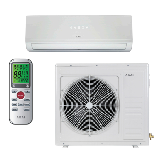
Product Overview • This Reverse Cycle Inverter Air Conditioner is made up of an indoor and outdoor unit (Fig. 1 & 2), which are connected through properly insulated copper pipes (not supplied) and an electrical connecting cable. • The indoor unit is installed on a wall of the room to be air conditioned. •... - Page 5 Product Overview (Cont.) (B) Outdoor Unit: Parts No Part 11 Air outlet grille 12 Outdoor unit rating label 13 Cover 14 Gas valve 15 Liquid valve Fig. 2 NOTE: The diagrams throughout this manual are for illustrative purposes only and may vary slightly from the appearance of the unit purchased. After Sales Support 1300 886 649 (AUS) 0800 836 761 (NZ) | info@tempo.org...
- Page 6 Product Overview (Cont.) Installation hardware Fig. 3 (for illustrative purposes only, not to scale) (C) Installation Hardware (D) Other inclusions Part (not pictured) Part Remote control holder (for wall- mounting) 16 Connection cable AAA Batteries (x2) 17 Copper nuts (x4) Instruction manual 18 Drainage pipe Quick start guide...
-
Page 7: Selecting The Installation Place
Selecting the Installation Place PROTECT YOUR WARRANTY These installation instructions for the Reverse Cycle Inverter Air Conditioner are for use by an appropriately qualified installer. Do not try to install the air conditioner on your own; doing so will expose you to danger and void the warranty. - Page 8 Selecting the Installation Place (Cont.) Outdoor unit Fig. 5 • Do not install the unit: • Near sources of heat, steam or flammable gas. • Where it is exposed to high winds or excessive dust. • Where people often pass. •...
-
Page 9: Installation
Installation Installation of the indoor unit • Before starting installation, decide on the position of the indoor and outdoor units, taking into account the minimum space required around the units. • Install the indoor unit in the room to be air conditioned, avoid installation in corridors or communal areas. -
Page 10: Refrigerant Piping Connection
Installation (Cont.) Electrical connections for the indoor unit • Lift the front panel. Fig. 9 • Take off the cover, as indicated (Fig. 9), by removing a screw or breaking the hooks. • For the electrical connections, see the circuit Wiring diagram diagram on the right part of the unit under the front panel. - Page 11 Installation (Cont.) Connecting the pipes • Do not remove the cap from the pipe until connecting it, to avoid dampness or dirt from entering. Fig. 11 • If the pipe is bent or pulled too often, it will become stiff. Do not bend it more than three times at one point.
- Page 12 Installation (Cont.) After having connected the pipe according to the instructions, install the connection cables, then the drain pipe (Fig. 14). After connection, lag the pipe, cables and drain pipe with the insulating material. • Arrange the pipes, cables and drain hose well. •...
-
Page 13: Installation Of The Outdoor Unit
Installation (Cont.) Installation of the outdoor unit • The outdoor unit should be installed on a solid wall, or on the ground, and fastened securely. • Before connecting pipes and cables, decide on the best position on the wall, leaving enough space for easy maintenance. •... - Page 14 Installation (Cont.) Connecting the pipes Screw the flare nuts to the outdoor unit coupling with the same tightening procedures described for the indoor unit. To avoid leakage, pay attention to the following points: • Tighten the flare nuts using two Fig.
- Page 15 Installation (Cont.) Proceed as illustrated in Fig. 19 and Fig. 20 below: • Unscrew and remove the caps from the 2-way and 3-way valves. • Unscrew and remove the cap from the service port. • Connect the vacuum pump hose to the service port. •...
- Page 16 Installation (Cont.) Final stage ind insulating covering around • W Insulating the joints of the indoor unit and fix it with insulating tape (Fig. 21). Piping Insulating • Fix the exceeding part of the signal cable to the piping or to Piping the outdoor unit.
-
Page 17: Wiring Diagrams
Wiring Diagram After Sales Support 1300 886 649 (AUS) 0800 836 761 (NZ) | info@tempo.org... -
Page 18: Information For The Installer
Information for the Installer Pipe details Inverter Air Conditioner Capacity 2.5kW 3.2kW Liquid pipe diameter 9.52mm (1/4”) (1/4”) (1/4”) (3/8”) Gas pipe diameter 9.52mm 12mm 12mm 15.88mm (3/8”) (1/2”) (1/2”) (5/8”) Length of pipe with standard charge Type of refrigerant R410A R410A R410A... - Page 19 Information for the Installer (Cont.) Cable wire specifications 2.5kW 3.2kW Model Capacity (kW) Sectional Area 1.0mm 1.0mm 1.5mm 2.5mm (min.) AWG18 AWG18 AWG16 AWG14 1.0mm 1.0mm 1.5mm 2.5mm Power Supply (min.) AWG18 AWG18 AWG16 AWG14 Cable 1.0mm 1.0mm 1.5mm 2.5mm (min.) AWG18 AWG18...
-
Page 20: Technical Specifications
Information for the Installer (Cont.) Technical specifications TAK-9000-25 Model Number Cooling 2.50kW Capacity Heating 2.60kW Cooling 670W Rated Power Heating 680W Cooling 3.6A Rated Current Heating 3.6A Cooling 6.0A Max. Input Current Heating 6.7A Cooling 1300W Max. Power Input Heating... - Page 21 Information for the Installer (Cont.) Technical specifications TAK-12000-32 Model Number Cooling 3.20kW Capacity Heating 3.20kW Cooling 840W Rated Power Heating 840W Cooling 5.0A Rated Current Heating 5.0A Cooling 5.3A Max. Input Current Heating 7.6A Cooling 1150W Max. Power Input Heating 1400W 15–23 Room size suitability...
- Page 22 Information for the Installer (Cont.) Technical specifications TAK-18000-50 Model Number Cooling 5.00kW Capacity Heating 5.20kW Cooling 1480W Rated Power Heating 1540W Cooling 6.7A Rated Current Heating 6.9A Cooling 10.3A Max. Input Current Heating 10.9A Cooling 2300W Max. Power Input Heating 2450W 25–40 Room size suitability...
- Page 23 Information for the Installer (Cont.) Technical specifications TAK-24000-70 Model Number Cooling 7.00kW Capacity Heating 7.50kW Cooling 2050W Rated Power Heating 2100W Cooling 9.4A Rated Current Heating 9.6A Cooling 13.5A Max. Input Current Heating 14.5A Cooling 2800W Max. Power Input Heating 2900W 30–50 Room size suitability...
- Page 24 Instruction Manual Revision Index Version No Issue Date Description V1.0 01 March 2016 Original release After Sales Support 1300 886 649 (AUS) 0800 836 761 (NZ) | info@tempo.org...
Need help?
Do you have a question about the TAK-9000-25 and is the answer not in the manual?
Questions and answers