
Related Manuals for DITEC Entrematic FACIL3H


Summary of Contents for DITEC Entrematic FACIL3H
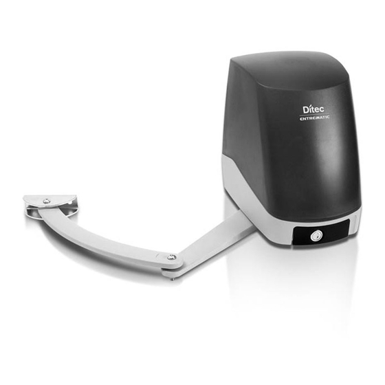
- Page 1 IP2132EN Ditec FACIL Technical Manual Swing gates automation (Original instructions) www.ditecentrematic.com...
-
Page 2: Table Of Contents
Index Subject Page General safety precautions General safety precautions for the user Declaration of incorporation of partly completed machinery Machinery Directive Technical specifications Operating instructions Standard installation Dimensions Installation Preliminary checks Bracket fastening Geared motor installation Limit switch installation and adjustment Electrical connections Routine maintenance plan Operating instructions... -
Page 3: General Safety Precautions
1. General safety precautions Failure to respect the information given in this manual may cause personal injury or damage to the device. Keep these instructions for future reference This installation manual is intended for qualified personnel only. Installation, electrical connections and adjustments must be performed by qualified person- nel, in accordance with Good Working Methods and in compliance with the current regulations. -
Page 4: General Safety Precautions For The User
General safety precautions for the user These precautions are an integral and essential part of the product and must be supplied to the user. Read them carefully since they contain important information on safe installation, use and maintenance. These instructions must be kept and forwarded to all possible future users of the system. -
Page 5: Declaration Of Incorporation Of Partly Completed Machinery
The manufacturer Entrematic Group AB, with headquarters in Lodjursgatan 10, SE-261 44 Land- skrona, Sweden, declares that the automation for swing gates type Ditec FACIL: - is designed to be installed on a manual gate to form a machine pursuant to Directive 2006/42/ EC. -
Page 6: Technical Specifications
3. Technical data FACIL3H FACIL3EH Power supply 24 V 24 V Absorption Torque 200 Nm 200 Nm Opening time 12÷32 s / 90° 12÷32 s / 90° Max. opening 110° 110° Service class 3 - FREQUENT 3 - FREQUENT S2 = 30 min S2 = 30 min Intermittence S3 = 50%... -
Page 7: Standard Installation
4. Standard installation Ref. Code Description Transmitter GOL4 Flashing light LAMPH Key selector XEL5 Codified via radio control keyboard GOL4M Magnetic loop detection device for traffic monitoring LAB9 Gearmotor FACIL3H Gearmotor and control panel incorporated FACIL3EH Photocells XEL2 Photocells IP55 LAB4 Connector block (not supplied). -
Page 8: Dimensions
5. Dimensions... -
Page 9: Installation
6. Installation The given operating and performance features can only be guaranteed with the use of DITEC Entrematic accessories and safety devices. Unless otherwise specified, all measurements are expressed in mm. 6.1 Preliminary checks Check that the structure is sufficiently rugged and that the hinge pivots are properly lubricated. -
Page 10: Bracket Fastening
6.2 Bracket fastening - Securely fix the fastening plate [8] to the gate pillar and the arm retention bracket [13] to the leaf as indicated in figure. Ø 8,5 Ø 8,5... -
Page 11: Geared Motor Installation
6.3 Gearmotor installation Remove the lid [7] and fit the gearmotor [9] to the fastening plate [8] as indicated in figure. Release the gearmotor (see use instructions). E2HFC BOXFC1 Fix the articulated arms and the arm retention bracket [13] as indicated in figure. The arm articulations must be lubricated and the screws sufficiently tightened so that they do not impede the movement of the arms. -
Page 12: Limit Switch Installation And Adjustment
6.4 Limit switch installation and adjustment (optional) - Connect the limit switch wire fastons to the microswitches. Arrange the limit switch wires neatly inside the microswitch box [1] and route the wire out through the appropriate opening. - Fit the two cams [3] on to the cam ring without tightening the screws. - Install the cam ring on the driving shaft and screw down screw [4] without tightening. -
Page 13: Electrical Connections
7. Electrical connections NB: the electrical connections and start-up of the FACIL gearmotors are shown in the VIVAH and E2HFC control panels installation manuals. Before connecting the power supply, make sure the plate data correspond to that of the mains power supply. An omnipolar disconnection switch with a contact opening distance of at least 3mm must be fitted on the mains supply. -
Page 14: Routine Maintenance Plan
8. Routine maintenance plan Perform the following operations and checks every 6 months according to intensity of use of the automation. Without 230 V~ power supply and batteries if present: Clean and lubricate the gate’s rotation pins and hinges with neutral grease. Check the resistance of the fixing points. -
Page 15: Operating Instructions
Operating instructions General safety precautions for the user These precautions are an integral and essential part of the product and must be supplied to the user. Read them carefully since they contain important information on safe installation, use and mainte- nance. - Page 16 Cleaning and maintenance work must not be carried out by children unless they are supervised. To ensure that the system works efficiently and correctly, the manufac- turer’s indications must be complied with and only qualified personnel must perform routine maintenance on the motorised door or gate. In particular, regular checks are recommended in order to verify that the safety devices are operating correctly.
-
Page 17: Manual Release Instructions
Manual release instructions In the event of a fault or a power failure, introduce the key, turn it clockwise and fully open the hatch. Manually open the gate. To lock the gate again, close the hatch, turn the key anticlockwise and remove the key NOTE: to turn off the automation the power supply and batteries (if present) must be disconnected. - Page 18 Installer's stamp Operator Date of intervention Technician's signature Customer's signature Intervention performed Installer's stamp Operator Date of intervention Technician's signature Customer's signature Intervention performed For any problems and/or information, contact the Technical Service. Entrematic Group AB Lodjursgatan 10 SE-261 44, Landskrona Sweden www.ditecentrematic.com...
- Page 19 All the rights concerning this material are the exclusive property of Entrematic Group AB. Although the contents of this publication have been drawn up with the greatest care, Entrematic Group AB cannot be held responsible in any way for any damage caused by mistakes or omissions. We reserve the right to make changes without prior notice.
- Page 20 Entrematic Group AB Lodjursgatan 10 SE-261 44, Landskrona Sweden www.ditecentrematic.com...
Need help?
Do you have a question about the Entrematic FACIL3H and is the answer not in the manual?
Questions and answers