DSC HS2016 User Manual
Alarm panel
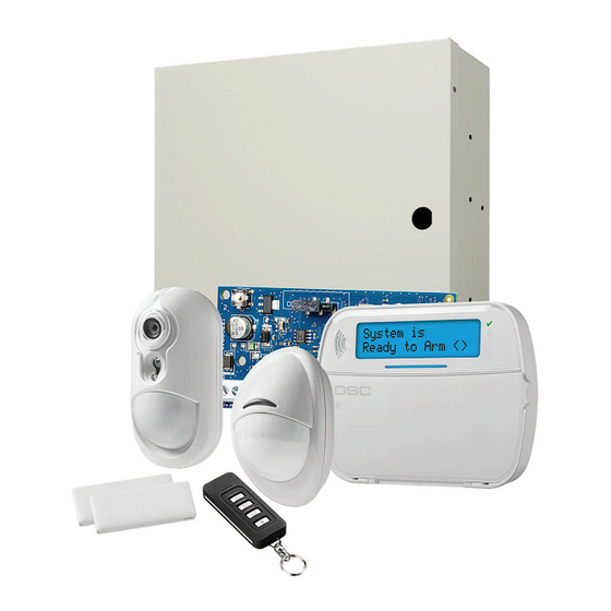
powerseries neo
Hide thumbs
Also See for HS2016:
- Reference manual (232 pages) ,
- User manual (56 pages) ,
- Installation manual (29 pages)
Table of Contents
Advertisement
Quick Links
Advertisement
Table of Contents
Troubleshooting

Related Manuals for DSC HS2016


Summary of Contents for DSC HS2016
- Page 1 HS2016/2032/2064/2128 Alarm Panel V1.1 User Guide WARNING: This manual contains information on limitations regarding product use and function and information on the limitations as to liability of the manufacturer. The entire manual should be care- fully read.
-
Page 2: Table Of Contents
Table of Contents 1.0 Quick Reference 2.0 Understanding your Keypad 2.1 Icon and LED Keypad Symbols 2.2 Keypad Models 3.0 The PowerSeries Neo Security System 3.1 General System Operation 3.2 Testing your System 3.3 Monitoring 3.4 Maintenance 4.0 Arming the System 4.1 Away Arming the System with the Keypad 4.2 Exit Delay Time Restart 4.3 Alarm Cancel Window 4.4 Using 2-way Wireless Keys and Proximity Tags 4.4.1 Arming the system with a 2-way wireless key 4.4.2 Arming the System with a Proximity Tag 4.5 Disarming the System 4.5.1 Disarming Error 5.0 Emergency Keys 6.0 Access Code Types 6.1 Adding, Changing and Deleting Access Codes 6.2 Burglary Verification 6.3 Swinger Shutdown 6.4 Call Waiting 6.5 Fire Alarm Verification 6.6 System Lockout due to Invalid Attempts 6.7 User Labels (LCD keypads only) 7.0 Trouble Conditions 8.0 Safety Instructions 8.1 Regular Maintenance and Troubleshooting 8.1.1 Cleaning 8.1.2 Troubleshooting 9.0 Reference Sheets 9.1 System Information 9.2 Service Contact Information 10.0 Access Code and Sensor/Zone information 11.0 Locating Detectors and Escape Plan 11.1 Smoke Detectors 11.2 Fire Escape Planning 11.3 Carbon Monoxide Detectors... -
Page 3: Quick Reference
Chapter 1.0 Quick Reference 1.0 Quick Reference The PowerSeries Neo Alarm System uses shortcut keys to access options or features on all models of keypads. When using an LCD keypad, the PowerSeries Neo Alarm System additionally uses a menu based navigation system. The scroll k eys can be used to [Scroll] through the list of options con- tained within the current menu. For more information on keypads see 2 “Understanding your Keypad Display”. Lookup detailed information on any of the listed actions using the accompanying Section number. For detailed information about the PowerSeries Neo Alarm System, refer to the full online manual, which can be accessed from the DSC.com Web site. Note: Some features must be enabled by installer. Note: Bypass Groups are not permitted in UL listed installations. Note: [*] - If configured by installer Status Function Status Emergency Emergency Function Keys Lights Keys Lights Keys Keys Ready - Indicates system normal. Must Stay Fire Alarm be on to arm system. All zones must be secured or bypassed and the system dis- armed for this light to activate. - Page 4 Chapter 1.0 Quick Reference Action Press Quick Arm/Quick Exit [*][0] Abort Arming Sequence [Access Code] Bypassing - All bypass commands begin with [*][1] + [Access Code*] Bypass Individual Zones [3 Digit Zone #] Bypass All Open Zones [9][9][8] Recall Last Bypass [9][9][9] Clear Bypass [0][0][0] OR [Scroll] Bypass Options + [*] + [Scroll] Clear Bypasses + [*] Program Bypass Group [3 digit zone #s] + [ 9][9][5] OR [3 digit zone #s] + [Scroll] Bypass Options + [*] + [Scroll] Prg Bypass Group + [*] Load Bypass Group [9][9][1] OR [Scroll] Bypass Options + [*] + [Scroll] Bypass Group + [*] Common Functions Set Time and Date [*][6] [Master Code] + [0][1]...
-
Page 5: Understanding Your Keypad
Chapter 2.0 Understanding your Keypad 2.0 Understanding your Keypad The PowerSeries Neo Alarm System supports a variety of wireless, hardwired and proximity sensor LCD, LED and Icon keypads. All keypads come equipped with the LED status lights described in section 1 "Quick Reference". HS2LCD series keypads display system messages on their LCD screen. HS2ICN series keypads display messages as described in 2.1 “Icon and LED Keypad Symbols”. HS2LED series keypads display messages via a series of numbered LEDs as described in 2.1 “Icon and LED Keypad Symbols”. All keypad versions will have a solid blue LED bar that is always on steady except when, if enrolled, a proximity tag is presented to and successfully read by the keypad. 2.1 Icon and LED Keypad Symbols HS2ICN Series HS2LED Series 1. Clock Digits 1, 2 These two 7 segment clock digits indicate the hour digits when the local clock is active. Digit 2 is also used to identify the zone num- ber as the 1 when the zone number is 100 or higher and the OPEN or ALARM icons are active. : (Colon) This icon is the hours/minutes divider and will flash once per second when the local clock is active. Clock Digits 3, 4 These two 7 segment displays are the minute digits when the local clock is active. The digits 3 and 4 are used to indicate the zone number for open zones or alarm in memory. These two digits com- bined with the clock digit 2, scroll one zone per second from the lowest number to the highest, when scrolling through zones. -
Page 6: Keypad Models
Chapter 2.0 Understanding your Keypad Chime This icon turns on when the Chime function key is pressed to enable Door Chime on the system. It will turn off when the chime function key is pressed again to disable Door Chime. OPEN This icon is used with clock digits 1 and 2 to indicate activated zones (not alarm) on the system. When zones are opened, the OPEN icon will turn on, and 7 segment displays 1 and 2 will scroll through the violated zones. Indicates that AC is present at the main panel. System Trouble Indicates that a system trouble is active. Night Indicates that the panel is armed in the Night Mode. Ready Light (green) If the Ready light is on, the system is ready for arming. If the toggle of the Ready LED flashes for Force Arming enabled, the LED flashes with force armable zones open on the partition. Armed Light (red) If the Armed light is on, the system has been armed successfully. Note: For UL listed installations, zones can only be bypassed manually. 2.2 Keypad Models Note: In the following list if x = 9 (the system operates in 912-919MHz), x=4 (the system operates in 433MHz band) or x=8 (the system operates in 868MHz band). Only models operating in 912- 919MHz band are UL/ULC listed. HS2LCD Alphanumeric LCD keypad HS2LCDP Alphanumeric LCD keypad with Prox. Tag support Icon keypad HS2ICN Icon keypad with Prox. Tag support HS2ICNP HS2LED LED keypad HS2LCDRFx... -
Page 7: The Powerseries Neo Security System
Chapter 3.0 The PowerSeries Neo Security System 3.0 The PowerSeries Neo Security System Your PowerSeries Neo has been designed to provide you with the greatest possible flexibility and convenience. Read this manual carefully and have your installer instruct you on how to operate your system and which features have been implemented in your system. All users of this system should be equally instructed in its use. Fill out section 17.1 "System Information" page with all of your zone information and access codes and store this manual in a safe place for future reference. Note: The PowerSeries Neo security system includes specific false alarm reduction features and is classified in accordance with ANSI/ SIA CP-01-2010 Control Panel Standard - Features for False Alarm Reduction. Please consult your installer for further information regarding the false alarm reduction features built into your system as all are not covered in this manual. 3.1 General System Operation Your security system is made up of a PowerSeries Neo control panel, one or more keypads and vari- ous sensors and detectors. The control panel will be mounted out of the way in a utility closet or in a basement. The metal cabinet contains the system electronics, fuses and standby battery. All the keypads have an audible indicator and command entry keys. LED keypads have a group of zone and system status lights. LCD keypads have an alphanumeric liquid crystal display (LCD). The keypad is used to send commands to the system and to display the current system status. The keypad(s) will be mounted in a convenient location inside the protected premises close to the entry/exit door(s). The security system has several zones of area protection and each of these zones is connected to one or more sensors (motion detectors, glassbreak detectors, door contacts, etc.). A sensor in alarm is indicated by the corresponding zone lights flashing on an LED keypad or by messages on the LCD keypad. Note: Only the installer or service professional shall have access to the control panel. -
Page 8: Monitoring
Chapter 3.0 The PowerSeries Neo Security System Press [04] or use the scroll keys t o navigate to System Test and Press (*) for <> press [*]. The system activates all keypad sounders, bells/sirens System Test and keypad LEDs for two seconds. To go back to the Ready state press [*]. 3.3 Monitoring This system is capable of transmitting alarms, troubles & emergency information to a central sta- tion. If you initiate an alarm by mistake, immediately call the central station to prevent an unne- cessary response. Note: For CP-01 systems, the monitoring function must be enabled by the installer before it becomes functional. There is a communicator delay of 30 seconds in this control panel. It can be removed, or it can be increased up to 45 seconds, at the option of the end-user by consulting with the installer. 3.4 Maintenance With normal use, the system requires minimum maintenance. Note the following points: Do not wash the security equipment with a wet cloth. Light dusting with a slightly moistened cloth should remove normal accumulations of dust. Use the system test described in “Testing Your System” to check the battery condition. We recommend, however, that the standby batteries be replaced every 3-5 years. For other system devices such as smoke detectors, passive infrared, ultrasonic or ... -
Page 9: Arming The System
Chapter 4.0 Arming the System 4.0 Arming the System The PowerSeries Neo system can be armed using a keypad, a 2-way wireless key or a proximity tag. 4.1 Away Arming the System with the Keypad Away mode activates the complete alarm system by: Arming all perimeter sensors. Arming all interior sensors. To Arm the System in Away Mode LCD Display 1. Ensure all windows and doors are closed and that the Ready Date Time indicator is on. JAN 02/13 2:06a 2. To arm using the Away key , press and hold the Away System is key f or 2 seconds and, if required, enter your [access code] or Ready to Arm present your proximity tag. -
Page 10: Exit Delay Time Restart
Chapter 4.0 Arming the System 4.2 Exit Delay Time Restart The control panel provides an option where, if a entry/exit zone is tripped a second time prior to the end of the exit delay, the exit delay time restarts. The exit delay timer can only be restarted once. 4.3 Alarm Cancel Window The control panel provides a period of time in which the user can cancel the alarm transmission. The minimum duration of this time is five minutes. If the programmed alarm transmission delay has expired, canceling an alarm sends a message to the monitoring station. Upon a successful transmission of the cancellation message the keypad will beep 6 times. Note: Must be enabled and configured by installer. Note: For CP-01 systems, alarm transmission delay must not exceed 45 seconds. 4.4 Using 2-way Wireless Keys and Proximity Tags 2-way wireless keys allow users in the close proximity of their house the ability to readily arm/dis- arm their system, and to call for help. For information on enrolling wireless keys see 7.1.3 "User Labels (LCD keypads only)". 1. Away Arm 1. ... -
Page 11: Disarming The System
Chapter 4.0 Arming the System To Arm the System with a Proximity tag Present your Proximity tag to a keypad equipped with a proximity sensor anytime the sys- tem Ready i ndicator is on. If configured by your installer, enter your access code. 4.5 Disarming the System Depending on your system configuration, there are multiple methods you can use to disarm your sys- tem. You can disarm the system using a: Keypad 2-way wireless key Proximity Tag To Disarm the System with a Keypad 1. Enter your [access code] or present your proximity tag anytime the system is armed. ... -
Page 12: Emergency Keys
Chapter 5.0 Emergency Keys 5.0 Emergency Keys IMPORTANT: EMERGENCY USE ONLY! Pressing both the emergency keys generates a Fire, Medical, or Panic Alarm, and alerts the mon- itoring station. e.g., to generate a medical alarm press both of the medical alarm keys f or 2 seconds and the display on an LCD keypad will show Hold down keys for Med. Alarm.The keypad beeps to indicate that the alarm input has been accepted and sent to the monitoring station. Fire Alarm Medical Alarm Panic Alarm Note: Verify with your alarm company that your system is equipped with emergency keys. Note: Fire keys can be disabled by the installer. Note: Having an optional audio verification module installed in your system allows the monitoring station to open 2-way communication when notified of an alarm. - 12 -... -
Page 13: Access Code Types
Chapter 6.0 Access Code Types 6.0 Access Code Types The alarm system provides the following user access code types: Code Add User Delete Arm Disarm Access User Func- Installer User Codes tions Master Yes Yes User Yes Yes All but All but Yes Yes Supervisor Master Master Duress Yes Yes One-time Yes 1/day user Installer and Master code are system codes that can be changed but not deleted. The other codes are ... -
Page 14: Adding, Changing And Deleting Access Codes
Chapter 6.0 Access Code Types 1. Press [*][5] Press (*) for <> Access Codes press [ *] and use the scroll keys t o navigate to Access Codes and press [*]. Enter [Master or supervisor code]. Present Tag or Enter Code Enter [2 digit user #] Press (*) for <> {User Label} scroll through the list of users and press [*]. On an LED keypad the user number will begin flashing. To go back to the Ready state press [#]. 6.1 Adding, Changing and Deleting Access Codes Each configured user is assigned a number from 01-95. Access codes cannot be duplicated. To Add or Change User Access Codes LCD Display 1. ... -
Page 15: Call Waiting
Chapter 6.0 Access Code Types Note: Must be enabled and configured by installer. 6.4 Call Waiting The Control Panel includes a programmable option for call waiting to prevent a call waiting line from interfering with the alarm verification process. This option is disabled by default. Note: Must be enabled and configured by installer. 6.5 Fire Alarm Verification Fire Alarm Verification is an available option for Fire zones. If configured, once the conditions for alarm verification are met the fire alarm will sound and an alarm transmission will be sent to the monitoring station. Note: Must be enabled and configured by installer. 6.6 System Lockout due to Invalid Attempts If too many invalid access codes are entered, your system can be configured to automatically lock out inputs from all keypads, wireless and proximity keys, and SMS commands for a specified dur- ation. When any keys are pressed, an error tone will sound. FMP keys are still active during Keypad Lockout. Note: Feature and lockout duration must be configured by installer. 6.7 User Labels (LCD keypads only) Adding or editing labels is done by using a pre-programmed word library. The following table lib- rary lists the full library and the associated three digit code. ... - Page 16 Chapter 6.0 Access Code Types Word Library 004 Active 044 Date 084 Garage 124 Mother’- 164 Service 204 A 005 Activity 045 Daughter’s 085 Gas 125 Motion 165 Shed 205 B 006 Alarm 046 Degrees 086 Glass 126 No 166 Shock 206 C 007 All 047 Delay...
- Page 17 Chapter 6.0 Access Code Types Word Library 033 Car 073 Feature 113 Load 153 Receive- 193 Zone 233 _(Under- score) 034 Carbon 074 Fence 114 Loading 154 Report 194 0 234 * 035 Central 075 Fire 115 Low 155 RF 195 1 235 # 036 Chime...
-
Page 18: Trouble Conditions
Chapter 7.0 Trouble Conditions 7.0 Trouble Conditions Trouble Conditions (Level 1) are comprised of various trouble types (Level 2) which may in turn be related to a specific zone, module, device or additional type of system equipment (Level 3). For an explanation of possible trouble conditions and the recommended actions required see Table 9-1. When the system detects a trouble condition the following occurs: The Trouble indicator t urns on. The keypad beeps once every 10 seconds. Press the [ *] key to silence the keypad beeps. Examining troubles is done by pressing [*][2]. When viewing troubles, the trouble indicator f lashes to identify the level of trouble being viewed. One flash = level 1, two flashes = level 2 etc. Trouble Conditions Trouble Condi- Trouble Description Trouble Trouble Trouble tion Types Notification Level 1 Level 2 Level 3 Note: Trouble #s are used to identify the number to view the trouble and depending on the keypad type being used, identifies which LED or digit illuminates to display the trouble. Similarly, Trouble Notification identifies the range that may be displayed on the keypad. When exploring the ... - Page 19 Chapter 7.0 Trouble Conditions Bus Voltage A module has detected a low HSM2HOST voltage on its corbus red ter- minal. Keypad Keypad 1-16 Zone Zone Expander expander 1- 15 Power Supply 05 Power sup- ply 1-4 High Current Output ter- Output minal 1-4 Output Output mod- Expander ule 1-16 HSM2955 Bus Voltage (Audio Expander) AC Troubles The system is experiencing ...
- Page 20 Chapter 7.0 Trouble Conditions Heat Freeze Probe Dis- connected Fire Zone Zone label or 001-128 Keypad Keypad 1-16 Siren Siren 1-16 Repeater Repeater 1- Device Battery 06 The system has detected an Zone Zone label issue with one or more of the or 001-128 device batteries. For Zone, Keypad and Wireless Key bat- tery troubles see the accom- panying documentation for how to change the batteries. For all ...
- Page 21 Chapter 7.0 Trouble Conditions Module Super- The system has detected a HSM2HOST vision supervisory trouble condition with one or more modules on the system. Call for service. Keypad Keypad 1-16 Zone Zone Expander Expander 1- Power Supply 05 Power sup- ply 1-4 High Current Output ter- Output minal 1-4 Output Output mod- Expander ule 1-16 Audio Expander Module The system has detected a HSM2HOST Tampers tamper condition with one or more modules on the system. ...
- Page 22 Chapter 7.0 Trouble Conditions FTC Trouble Receiver 1- SIM Lock Cellular Ethernet Receiver Receiver 1- Supervision Receiver 1- Receiver Alt Comm Fault Alternate Receiver 1- Communicator Not Networked 12 The system has detected a net- Zone Zone label work trouble condition with 001-128 one or more modules on the system. If the trouble does not restore within 20 minutes, call for service. Keypad Keypad 1-16 Siren Siren 1-16 Repeater Repeater 1- User Users 01-95 - 22 -...
-
Page 23: Safety Instructions
Chapter 8.0 Safety Instructions 8.0 Safety Instructions This equipment is stationary-fixed and must be installed by Service Persons only (Service Person is defined as a person having the appropriate technical training and experience necessary to be aware of hazards to which that person may be exposed in performing a task and of measures to minimize the risks to that person or other persons). It must be installed and used within an environment that provides the pollution degree max 2, over voltages category II, in non-hazardous, indoor locations only. WARNING! When using equipment connected to the mains and/or to the telecommunication net- work, there are basic safety instructions that should always be followed. Refer to the safety instruc- tions provided with this product and save them for future reference.To reduce the risk of fire, electric shock and/or injury, observe the following: Do not attempt to service this product yourself. Opening or removing the cover may expose you to dangerous voltage or other risk. Refer servicing to service persons. Never open the device yourself. Use authorized accessories only with this equipment. DO NOT leave and/or deposit ANY object on the top of the cabinet of this equipment! The cabinet as it is installed on the wall is not designed to support any supplementary weight! Do not spill any liquids on the cabinet. Do not touch the equipment and its connected cables during an electrical storm; there may be a risk of electric shock. Never touch uninsulated wires or terminals unless the equipment has been disconnected from the mains supply and from the telecommunication network! Ensure that cables are positioned so that accidents cannot occur. Connected cables must not be subject to excessive mechanical strain. Do not spill any type of liquid on the equip- ment. ... -
Page 24: Troubleshooting
Chapter 8.0 Safety Instructions 8.1.2 Troubleshooting Occasionally, you may have a problem with your Alarm Controller or telephone line. If this hap- pens, your Alarm Controller will identify the problem and displays an error message. Refer to the provided list when you see an error message on the display. If additional help is required, contact your distributor for service. Note: There are no parts replaceable by the end-user within this equipment, except for the keypad batteries. Dispose of used batteries as per local rules and regulations. This publication covers the following models x = 9 (912-919MHz UL/ULC systems) 4 (433MHz) or 8 (868MHz). HS2016 HS2LCD HS2LCDWFx HS2ICN HS2128 HS2LCDP HS2LCDWFPx HS2ICNP HS2032 HS2LCDRFx HS2LCDWFPVx HS2ICNRFx ... -
Page 25: Reference Sheets
Chapter 9.0 Reference Sheets 9.0 Reference Sheets Fill out the following information for future reference and store this guide in a safe place. 9.1 System Information Mark if Buttons are Enabled o [ F] FIRE o [ M] Medical o [ P] PANIC The Exit Delay Time is _______ seconds. The Entry Delay Time is _______ s econds. 9.2 Service Contact Information Central Station Information Account #: ___________________ ... -
Page 26: Access Code And Sensor/Zone Information
Chapter 10.0 Access Code and Sensor/Zone information 10.0 Access Code and Sensor/Zone information Master Code [01] : _________________________ Access Code Reference Sheet Code Access Code Code Access Code Code Access Code Code Access Code ... - Page 27 Chapter 10.0 Access Code and Sensor/Zone information Sensor Protected Area Sensor Type Sensor Protected Area Sensor Type ...
- Page 28 Chapter 10.0 Access Code and Sensor/Zone information Sensor Protected Area Sensor Type Sensor Protected Area Sensor Type ...
-
Page 29: Locating Detectors And Escape Plan
Chapter 11.0 Locating Detectors and Escape Plan 11.0 Locating Detectors and Escape Plan Locating Detectors and Escape Plan The following information is for general guidance only and it is recommended that local fire codes and regulations be consulted when locating and installing smoke and CO alarms. 11.1 Smoke Detectors Research has shown that all hostile fires in homes generate smoke to a greater or lesser extent. Experiments with typical fires in homes indicate that detectable quantities of smoke precede detect- able levels of heat in most cases. For these reasons, smoke alarms should be installed outside of each sleeping area and on each storey of the home. The following information is for general guidance only and it is recommended that local fire codes and regulations be consulted when locating and installing smoke alarms. It is recommended that additional smoke alarms beyond those required for minimum protection be installed. Additional areas that should be protected include: the basement; bedrooms, especially where smokers sleep; dining rooms; furnace and utility rooms; and any hallways not protected by the required units. On smooth ceilings, detectors may be spaced 9.1m (30 feet) apart as a guide. Other spacing may be required depending on ceiling height, air movement, the presence of joists, uninsulated ceilings, etc. Consult National Fire Alarm Code NFPA 72, CAN/ULC-S553-02 or other appropriate national standards for installation recommendations. Do not locate smoke detectors at the top of peaked or gabled ceilings; the dead air space in these locations may prevent the unit from detecting smoke. Avoid areas with turbulent air flow, such as near doors, fans or windows. Rapid air move- ment around the detector may prevent smoke from entering the unit. Do not locate detectors in areas of high humidity. ... -
Page 30: Fire Escape Planning
Chapter 11.0 Locating Detectors and Escape Plan Figure 1 Figure 3 Figure 2 Figure 3a Figure 4 11.2 Fire Escape Planning There is often very little time between the detection of a fire and the time it becomes deadly. It is thus very important that a family escape plan be developed and rehearsed. 1. Every family member should participate in developing the escape plan. Study the possible escape routes from each location within the house. Since many fires occur at night, special attention should be given to the escape routes from sleeping quarters. Escape from a bedroom must be possible without opening the interior door. Consider the following when making your escape plans: Make sure that all border doors and windows are easily opened. Ensure that they are not painted shut, and that their locking mechanisms operate smoothly. If opening or using the exit is too difficult for children, the elderly or handicapped, plans for rescue should be developed. This includes making sure that those who are to perform the rescue can promptly hear the fire warning signal. If the exit is above the ground level, an approved fire ladder or rope should be provided as well as training in its use. Exits on the ground level should be kept clear. Be sure to remove snow from exterior patio doors in winter; outdoor furniture or equipment should not block exits. Each person should know the predetermined assembly point where everyone can be accoun- ted for (e.g., across the street or at a neighbor's house). Once everyone is out of the build- ing, call the fire department. -
Page 31: Carbon Monoxide Detectors
Chapter 11.0 Locating Detectors and Escape Plan Write the fire escape plan down and rehearse it frequently so that should an emergency arise, everyone will know what to do. Revise the plan as conditions change, such as the number of people in the home, or if there are changes to the building’s construction. Make sure your fire warning system is operational by conducting weekly tests. If you are unsure about system operation, contact your installer. We recommend that you contact your local fire department and request further information on fire safety and escape planning. If available, have your local fire prevention officer conduct an in-house fire safety inspection. Figure 5 11.3 Carbon Monoxide Detectors Carbon monoxide is colorless, odorless, tasteless, and very toxic, it also moves freely in the air. CO detectors can measure the concentration and sound a loud alarm before a potentially harmful level is reached. The human body is most vulnerable to the effects of CO gas during sleeping hours; there- fore, CO detectors should be located in or as near as possible to sleeping areas of the home. For maximum protection, a CO alarm should be located outside primary sleeping areas or on each level of your home. Figure 5 indicates the suggested locations in the home. Do NOT place the CO alarm in the following areas: Where the temperature may drop below -10ºC or exceed 40ºC Near paint thinner fumes Within 5 feet (1.5m) of open flame appliances such as furnaces, stoves and fireplaces In exhaust streams from gas engines, vents, flues or chimneys Do not place in close proximity to an automobile exhaust pipe; this will damage the detector PLEASE REFER TO THE CO DETECTOR INSTALLATION AND OPERATING ... -
Page 32: Regulatory Agency Statements
- Connect the equipment into an outlet on a circuit different from that to which imply that Industry Canada approved the equipment. NOTICE: The Ringer Equivalence Number (REN) for this terminal equipment is the receiver is connected. - Consult the dealer or experienced radio/television technician for help. 0.1. The REN assigned to each terminal equipment provides an indication of the The user may find the following booklet prepared by the FCC useful: “How to maximum number of terminals allowed to be connected to a telephone interface. Identify and Resolve Radio/Television Interference Problems”. This booklet is The termination on an interface may consist of any combination of devices sub- available from the U.S. Government Printing Office, Washington D.C. 20402, Stock ject only to the requirement that the sum of the Ringer Equivalence Numbers of # 004-000-00345-4. all devices does not exceed 5. The keypads represented in this manual can be used with the following Control HS2016 Registration number I C:160A-HS2128 Units: HS2016, HS2032, HS2064, HS2128. HS2032 Registration number I C:160A-HS2128 HS2064 Registration number I C:160A-HS2128 IMPORTANT INFORMATION HS2128 Registration number I C:160A-HS2128 This equipment complies with Part 68 of the FCC Rules and, if the product was approved July 23, 2001 or later, the requirements adopted by the ACTA. On the This product is in conformity with EMC Directive 2004/108/EC based on results side of this equipment is a label that contains, among other information, a product using harmonized standards in accordance with article 10(5), R&TTE Directive identifier. If requested, this number must be provided to the Telephone Company. 1999/5/EC based on following Annex III of the directive and LVD Directive HS2016 Product Identifier U S:F53AL01BHS2128 2006/95/EC based on results using harmonized standards. - Page 33 Chapter 12.0 Regulatory Agency Statements The grant of a Telepermit for any item of terminal equipment indicates only that Telecom has accepted that the item complies with minimum conditions for con- nection to its network. It indicates no endorsement of the product by Telecom, nor does it provide any sort of warranty. Above all, it provides no assurance that any item will work correctly in all respects with another item of Telepermitted equip- ment of a different make or model, nor does it imply that any product is com- patible with all of Telecom's network services. REVERSE NUMBERING (DECADIC SIGNALLING) Decadic signaling should not be used as it is being progressively phased out of the network. DTMF dialling is 100% available and it should always be used. LINE GRABBING EQUIPMENT This equipment is set up to carry out test calls at pre-determined times. Such test calls will interrupt any other calls that may be set up on the line at the same time. The timing set for such test calls should be discussed with the installer. The timing set for test calls from this equipment may be subject to 'drift'. If this proves to be inconvenient and your calls are interrupted, then the problem of timing should be discussed with the equipment installer. The matter should NOT be repor- ted as a fault to Telecom Faults Service. D.C.LINE FEED TO OTHER DEVICES During dialing, this device unit does not provide DC voltage to the series port con- nection.This may cause loss of memory functions for the terminal devices (local telephone) connected to T-1, R-1. General operation (ringer sensitivity and loading) This device only responds to Distinctive Alert cadences DA1 and DA2. In the event of any problem with this device, it is to be disconnected. A CPE item connected to one of the device’s terminal ports may be connected directly in its place. The user should then arrange for the product to be repaired. Should the mat- ter be reported to Telecom as a wiring fault, and the fault is proven to be due to this product, a call-out charge will be incurred. - 33 -...
- Page 36 © 2014 Tyco International Ltd. and its Respective Companies. All Rights Reserved. Tech Support: 1-800-387-3630 (Canada & U.S.) or 905-760-3000 Printed in Canada • w ww.dsc.com The trademarks, logos, and service marks displayed on this document are registered in the United States [or other countries]. A ny misuse of the trademarks is strictly prohibited and Tyco International Ltd. will aggressively enforce its intellectual property rights to the fullest extent of the law, including pursuit of criminal prosecution ...
Need help?
Do you have a question about the HS2016 and is the answer not in the manual?
Questions and answers