DSC neo HS2016 User Manual
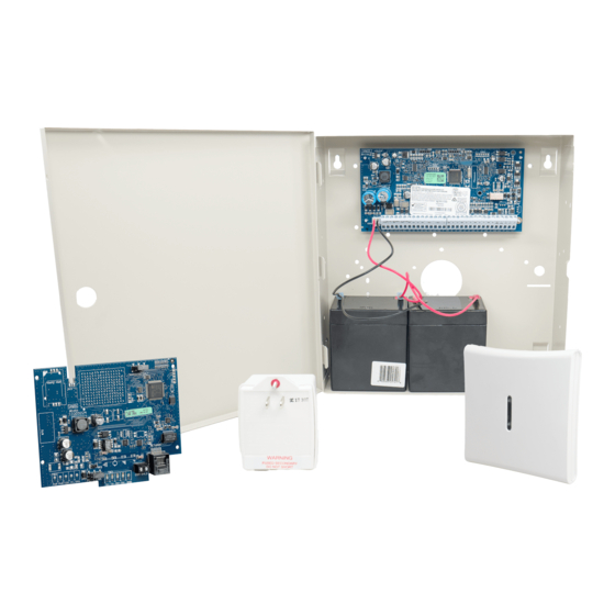
Powerseries alarm panel
Hide thumbs
Also See for neo HS2016:
- Reference manual (232 pages) ,
- User manual (56 pages) ,
- Installation manual (29 pages)
Table of Contents
Advertisement
Advertisement
Table of Contents
Troubleshooting

Related Manuals for DSC neo HS2016


Summary of Contents for DSC neo HS2016
- Page 1 HS2016/2032/2064/2128 Alarm Panel V1.0 User Guide WARNING: This manual contains information on limitations regarding product use and function and information on the limitations as to liability of the manufacturer. The entire manual should be carefully read.
-
Page 2: Table Of Contents
Table of Contents 1 Quick Reference 2 Understanding your Keypad Display Icon and LED Keypad Symbols ................ 4 Keypad Models ....................5 3 About your PowerSeries Neo security system General System Operation ................5 Monitoring ......................6 Maintenance ..................... 6 4 Arming the System Away Arming the System with the Keypad ............ -
Page 3: Quick Reference
1 Quick Reference The PowerSeries Neo Alarm System uses shortcut keys to access options or features on all models of keypads. When using an LCD keypad, the PowerSeries Neo Alarm System additionally uses a menu based navigation system. The scroll keys can be used to [Scroll] through the list of options contained within the current menu. -
Page 4: Understanding Your Keypad Display
2 Understanding your Keypad Display The PowerSeries Neo Alarm System supports a variety wireless, hardwired and proximity sensor LCD, LED and Icon keypads. All keypads come equipped with the LED status lights described in 1 "Quick Reference". HS2LCD series keypads display system messages on their LCD screen. HS2ICN series keypads display messages as described in 2.1 “Icon and LED Keypad Symbols”. -
Page 5: Keypad Models
2.2 Keypad Models In the following list below if x = 9 (the system operates in 912-919MHz), 4 (the system operates NOTES: in 433MHz band) or 8 (the system operates in 868MHz band). Only models operating in 912-919MHz band are UL/ULC listed. HS2LCD Alphanumeric LCD keypad Alphanumeric LCD keypad with Prox. -
Page 6: Monitoring
3.2 Testing your System Tests all system keypad LED’s, keypad sounders, bells and/or sirens. To insure that your system continues to function as intended, you must test your IMPORTANT • system weekly. For UL HOME HEALTH CARE listed applications the system shall also be tested •... -
Page 7: Exit Delay Time Restart
To Arm the System in Away Mode LCD Display 1. Ensure all windows and doors are closed and that the Ready indicator is on. Date Time JAN 02/13 2:06a 2. To arm using the Away key, press and hold the Away key for 2 seconds System is Ready to Arm... -
Page 8: Arming The System With A 2-Way Wireless Key
4.2 Using 2-way Wireless Keys and Proximity Tags 2-way wireless keys allow users in the close proximity of their house the ability to readily arm/disarm their system, and to call for help. For information on enrolling wireless keys see 6.7 "User Labels (LCD keypads only)". -
Page 9: Disarming Error
To Disarm the System with a Keypad (Continued) • If you walk through the entry door, the keypad will beep. Enter your code within _____ seconds to avoid an alarm condition. To Disarm the System with a 2-way wireless key •... -
Page 10: Adding, Changing And Deleting Access Codes
The Master code is a system code that can be changed but not deleted. The other codes are user-defined and can be added or deleted as necessary. By default, access codes have the same partition and attribute programming as the code used to program them. When using 6-digit access codes, the minimum number of variations of access codes are 10526. -
Page 11: Cross Zoning
To Delete a User Access Code LCD Display 2. Press and the code is deleted, and you are returned to the previous Enter New Code 030516 screen. The flag is changed to - from P. On an ICN or LED keypad the pro- then grammed user will have their digits cease being displayed. - Page 12 To Edit a User Label (Continued) LCD Display 3. Use the arrow keys to scroll through the list of words or use the [3- digit number] to display the desired word. Press to select the word. 4. To enter an additional word repeat step 3, Table 1-1 Word Library Item Text...
-
Page 13: Trouble Conditions
Trouble Conditions Trouble Conditions (Level 1) are comprised of various of trouble types (Level 2) which may in turn be related to a specific zone, module, device or additional type of system equipment (Level 3). For an explanation of possible trouble conditions and the recommended actions required see Table 1-2. When the system detects a trouble condition the following occurs: •... - Page 14 Table 1-2 Trouble Conditions (Continued) Trouble Trouble # Description Trouble Types Trouble # Trouble Condition Notification Level 1 Level 2 Level 3 Device Battery The system has detected an issue with one or Zone Zone label or 001-128 more of the device batteries. For Zone, Keypad Keypad 1-16 Keypad and Wireless Key battery troubles see...
-
Page 15: Installer Warning
Installer Warning WARNING Please Read Carefully N o t e t o I ns ta l l er s positioned. Smoke may not be able to reach the smoke detectors, such as when the fire is in a chimney, walls or roofs, or on the other This warning contains vital information. -
Page 16: Safety Instructions
9 Safety Instructions This equipment has no mains on/off switch. the plug of the direct plug-in power supply is WARNING: intended to serve as the disconnecting device if the equipment must be quickly disconnected. it is imperative that access to the mains plug and associated mains socket/outlet, is never obstructed. -
Page 17: Eula
EULA, even if this EULA is deemed to be a modification of any previous ENTIRE LIABILITY UNDER ANY PROVISION OF THIS LICENSE arrangement or contract. If You do not agree to the terms of this EULA, DSC is AGREEMENT SHALL BE LIMITED TO THE GREATER OF THE AMOUNT... -
Page 18: System Information
11 System Information Mark if Buttons are Enabled FIRE AUXILIARY PANIC The Exit Delay Time is _______ seconds. The Entry Delay Time is _______ seconds. 11.1 Service Contact Information Central Station Information Account#: ___________________ Telephone#: __________________ Installer Information: Company: ___________________ Telephone#: __________________ Battery Installation / Service Date: _____________________ _____________________... - Page 19 11.3 Access Code and Sensor / Zone information Master Code [40] : _________________________ Table 1-3 Access Code Reference sheet Code Access Code Code Access Code Code Access Code Code Access Code...
- Page 20 Table 1-4 Sensor / Zone Information Sensor Protected Area Sensor Type Sensor Protected Area Sensor Type...
- Page 21 Table 1-4 Sensor / Zone Information Sensor Protected Area Sensor Type Sensor Protected Area Sensor Type...
-
Page 22: Locating Smoke And Co Detectors
12 Locating Smoke and CO Detectors The following information is for general guidance only and it is recommended that local fire codes and regulations be consulted when locating and installing smoke and CO alarms. 12.1 Smoke Detectors Research has shown that all hostile fires in homes generate smoke to a greater or lesser extent. Experiments with typical fires in homes indicate that detectable quantities of smoke precede detectable levels of heat in most cases. -
Page 23: Fire Escape Planning
12.2 Fire Escape Planning There is often very little time between the detection of a fire and the time it becomes deadly. It is thus very important that a family escape plan be developed and rehearsed. 1. Every family member should participate in developing the escape plan. 2. -
Page 24: Regulatory Agency Statements
This equipment is of a type that is not intended to be re- paired by the end user. DSC c/o APL Logistics 757 Douglas Hill Rd, Lithia Springs, GA 30122 Additional Information Connection to party line service is subject to state tariffs. Contact the state public utility commission, public service commission or corporation com- mission for information. - Page 25 INDUSTRY CANADA STATEMENT The following is a list of warnings applicable when this equipment is con- NOTICE: The models: HS2128, HS2064, HS2032, HS2016 meet the appli- nected to the New Zealand Telecom Network. cable Industry Canada Terminal Equipment Technical Specifications. This is confirmed by the registration number.
- Page 28 © 2014 Tyco International Ltd. and its Respective Companies. All Rights Reserved. Toronto, Canada • www.dsc.com • The trademarks, logos, and service marks displayed on this document are registered in the United States [or other countries]. Any misuse of the trademarks is strictly prohibited and Tyco International Ltd. will aggressively enforce its intellectual property rights to the fullest extent of the law, including pursuit of criminal prosecution wherever necessary.
Need help?
Do you have a question about the neo HS2016 and is the answer not in the manual?
Questions and answers