Advertisement
Quick Links
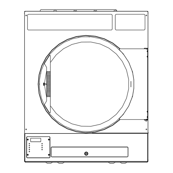
INDUSTRIAL DRYER
MODEL T-30SWD ON-PREMISE
B-SERIES CONTROL, ELECTRIC-HEATED
OPERATOR'S MANUAL
INSTALLATION & OPERATION INSTRUCTIONS
The dryer must not be stored or installed where it will be exposed to water and/or weather and is
suitable for use in room temperatures between 40F and 105F (5C and 45C.)
Post the following "For Your Safety" caution in a prominent location:
FOR YOUR SAFETY
Do not store or use gasoline or other flammable vapors or liquids in the vicinity of this or any
other appliance or machine.
It is important that you read this Manual and retain it for future reference.
For service or
replacement parts, contact the Dexter Distributor in your area or the manufacturer.
WARNING / Avertissement
WARNING – Risk of Fire / Avertissement: Risque d'incendie
Clothes dryer installation must be performed by a qualified installer. / L'installation de la
sécheuse doit être effectuée par un spécialiste qualifié.
Install the clothes dryer according to the manufacturer's instructions and local codes.
Do not install a clothes dryer with flexible plastic venting materials. If flexible metal (foil type)
duct is installed, use duct that has been investigated and found acceptable for use with clothes
dryers. Flexible venting materials are known to collapse, be easily crushed, and trap lint. These
conditions will obstruct clothes dryer airflow and increase the risk of fire. / Ne pas installer une
sécheuse avec des matériaux de ventilation en plastique. Dans le cas où un conduit en métal
flexible (du genre à feuille) est installé, il doit être d'un type spécifique identifié par le fabricant
de l'appareil comme acceptable pour les sécheuses. Les matériaux de ventilation flexibles sont
réputés pour s'aplatir, se déformer facilement et collecter de la peluche. Ces conditions vont
obstruer l'écoulement d'air de la sécheuse et augmenter le risque d'incendie.
To reduce the risk of severe injury or death, follow all installation instructions. / Pour réduire le
risque de blessures graves ou mortelles, suivre toutes les instructions d'installation.
Save these instructions. / Garder les instructions.
Dexter Laundry, Inc.
2211 West Grimes Avenue
Fairfield, Iowa 52556
8514-289-001 REV A PAGE 1
Advertisement

Related Manuals for Dexter Laundry T-30SWD


Summary of Contents for Dexter Laundry T-30SWD
- Page 1 INDUSTRIAL DRYER MODEL T-30SWD ON-PREMISE B-SERIES CONTROL, ELECTRIC-HEATED OPERATOR’S MANUAL INSTALLATION & OPERATION INSTRUCTIONS The dryer must not be stored or installed where it will be exposed to water and/or weather and is suitable for use in room temperatures between 40F and 105F (5C and 45C.) Post the following “For Your Safety”...
- Page 2 TABLE OF CONTENTS Page No. Warnings about use and operation Dryer Specifications Dryer Dimensions (Figure 1) Uncrating Vertical Clearance Dimensions (Figure 2) Dryer Exhaust System (Figure 3) Dryer Shutdown Operating Instructions Servicing and Troubleshooting Preventative Maintenance Instructions WARNINGS ABOUT USE AND OPERATION DO NOT MODIFY THIS APPLIANCE.
- Page 3 SPECIFICATIONS 30 lb. Commercial Dryer: T-30 SWD DNS030E_-(71/74/77/78/79) Cabinet Height (As a stand-alone dryer) 38 7/8” 987 mm. (Assumes minimum leveling leg adjustment) Cabinet Height (Combo washer/dryer) 78 3/4” 2000 mm. Cabinet Width 31 1/2” 800 mm. Overall Depth 49 7/16 1256 mm.
- Page 4 Electrical Specifications – Model -79 Voltage/Hz/Phase 400V/50Hz/3Phase/24kW Heat Running Amps Minimum Dual Element Time Delay Fuse 50 Amp Wire Size #6 (13.3 mm^2) Electrical Service 4 wire + ground Stand-alone Dryer Shipping Weight 420 lbs. 191 kg. Net Weight 380 lbs. 172 kg.
- Page 5 8514-289-001 REV A PAGE 5...
- Page 6 INSTALLATION AND OPERATING INSTRUCTIONS This dryer may have been supplied as part of a washer/dryer stacked appliance. If so, refer to the washer instructions for uncrating and hard mounting the stacked unit to a concrete floor and observe the dryer clearances listed below. STACK WASHER / DRYER INSTALLATION (when necessary): 1.
- Page 7 FIGURE 2 - VERTICAL CLEARANCE DIMENSIONS 3. MAKE-UP AIR: Adequate make-up air must be supplied to replace air exhausted by dryers on all types of installations. Refer to specifications for the minimum amount of make-up air opening to outside for each dryer. This is a net requirement of effective area.
- Page 8 HEATING SUPPLY MINIMUM DUAL ELEMENT TIME MINIMUM WIRE SIZE FROM FUSED ELEMENT SIZE VOLTAGE DELAY FUSE SIZE AT FUSED DISCONNECT TO DRYER TERMINAL (kW) (PHASE / V.) DISCONNECT (A.) BLOCK (75 C COPPER WIRE) 1 / 208 / 60 hz (1/0) 1 / 240 / 60 hz (1/0)
- Page 9 4. EXHAUST INSTALLATION. (Refer to Figure 3) Exhausting of the dryer(s) should be planned and constructed so that no air restrictions occur. Any restriction due to pipe size or type of installation can cause slow drying time, excessive heat, and lint in the room. From an operational standpoint, incorrect or inadequate exhausting can cause a cycling of the high limit thermostat, which shuts off the heating elements and results in inefficient drying.
- Page 10 Caution - A clothes dryer produces combustible lint and should be exhausted outdoors. The area around the clothes dryer should be kept free of lint. DRYER SHUTDOWN To render the dryer inoperative, disconnect electrical power to the dryer. IT IS RECOMMENDED THAT THE INSTALLER TEST THE DRYER FOR OPERATION AND INSTRUCT THE USER BEFORE LEAVING THE INSTALLATION.
- Page 11 8514-289-001 REV A PAGE 11...
- Page 12 DRYER CONTROLLER FACTORY DEFAULT PROGRAM SETTINGS COOL DOWN TOTAL CYCLE DRYING TIME TIME TEMPERATURE DRYER LOAD CYCLE (MINUTES) (MINUTES) Towels, pads, heavy cotton Sheets, blended materials Cotton Synthetic materials Blended materials DRYER FAULT CODES FAULT# FAULT DESCRIPTION ACTION Dryer stops and “F1” flashes on the 4-digit display. Shorted thermostat When short circuit on sensor input is removed, sensor.
- Page 13 TOUCH PAD DESCRIPTION INDICATOR LIGHTS (L.E.D.s) Description Cycle (1 through 5) These L.E.D.s are on solid when a particular cycle is chosen for operation or programming. Heating Elements This L.E.D. is part of the 4-digit numeric display and will be on solid during the drying part of a cycle when the heating elements do not need to be on.
- Page 14 SWITCHES (Pushbuttons) - continued Description This touch pad switch will start the operation of a dry cycle if pressed and released once. Pressing and holding this touch pad switch will display the current temperature of the dryer heat sensor as long as it Start is held in the depressed position.
- Page 15 OPERATING INSTRUCTIONS WARNING: To reduce the risk of fire, electric shock, or injury to persons, read the IMPORTANT SAFETY INSTRUCTIONS before operating this appliance. Maximum Load Capacity: 30 Pounds (13.6kg) Dry Weight To dry a load of items, you must choose one of the five-programmed dry cycles. Each of these five dry cycles may be modified in two different ways to match your load.
- Page 16 The letter “C” represents the cool down portion of the dry cycle. The two digits represent the amount of time remaining in the dry cycle. The two-digit time, shown on the dryer controller display, will count down to zero. When the time decrements to zero, the dryer controller display will flash the word “donE” and the end of cycle tone will sound.
- Page 17 The push button, which is located at the lower middle side of the component side of the dryer controller circuit board, is used to reset all five of the dry cycles to the factory default settings. It is labeled as DEFAULT SETTINGS. Even the dry cycles that have been modified using the permanent programming procedure will be changed back to the factory default settings when using this push button.
- Page 18 dry cycle that you want to change (dry cycle 1 through 5). The dry cycle L.E.D. will illuminate to indicate which dry cycle you are choosing. If you press either the UP or DOWN touch pad switch and hold it down, the controller will sequence through the five dry cycles.
- Page 19 programming L.E.D. will switch off, the dry cycle L.E.D. will remain on, and the flashing cool down time on the 4-digit display will stop flashing and remain. 10) At this point, you have two choices. a. You can perform the modified dry cycle by pressing and releasing the START touch pad switch on the dryer controller.
- Page 20 TEMPORARY DRYER CONTROLLER PROGRAMMING EXAMPLE REQUIREMENTS: Dry a load with 40 minutes of actual heat at 185 F and five minutes of cool down. The following procedure will show you how to temporarily modify the existing dry cycle 1 program for one cycle of drying. It is based on the assumption that the factory defaults have not been permanently changed.
- Page 21 controller is pressed and released twice, consecutively, the dry cycle 1 program will revert to the factory default settings. If you press the START touch pad switch on the dryer controller, the controller display will change from the number “5” to the number “45” and dry cycle 1 will begin. PERMANENT DRYER CONTROLLER PROGRAMMING The permanent programming mode will allow the change of the stored dry cycle settings in the dryer controller until the operator physically changes them again.
- Page 22 6) Press and release either the UP or DOWN touch pad switch on the dryer controller to change the total dry time. Once either the UP or DOWN touch pad switch is pressed, the dry time L.E.D. and the total dry time on the 4-digit numeric display will flash. If you press and hold down either the UP or DOWN touch pad switch, you will increment (UP arrow) or decrement (DOWN arrow) through the total dry times available (1 through 60 minutes).
- Page 23 continue at step 6 of this procedure. If you want to modify another dry cycle program, go to step 4 of this procedure and continue. 13) If you pressed the STOP touch pad switch on the dryer controller to escape the programming mode, you may now start the dry cycle by pressing the START touch pad switch on the dryer controller.
- Page 24 8) Press and release the SELECT/ENTER touch pad switch on the dryer controller. The dry time L.E.D. and the programming L.E.D. will remain on, the temperature L.E.D. will switch off, the cool down L.E.D. will illuminate, and the dryer controller display will show the number “5”.
- Page 25 SERVICING THE DRYER CAUTION: Label all wires prior to disconnection when servicing controls. Wiring errors can cause improper and dangerous operation. Verify proper operation after servicing. ATTENTION: Au moment de l'entretien des commandes, étiquetez tous les fils avant de les débrancher. Des erreurs de câblage peuvent entraîner un fonctionnement inadéquat et dangereux.
- Page 26 PREVENTIVE MAINTENANCE INSTRUCTIONS Routine Non-Technical Maintenance and Cleaning: Daily A. Clean lint screens. Use soft brush if necessary. Failure to do so will slow drying, increase temperatures throughout the dryer and increase the risk of fire. Dryer must not be operated without lint screen in place.
- Page 27 For service and parts information, contact your local Dexter agent. To find your local Dexter agent, use the Distributor Locator at the website shown below. If a Dexter agent is not available, contact Dexter Laundry, Inc. directly as listed below:...
Need help?
Do you have a question about the T-30SWD and is the answer not in the manual?
Questions and answers