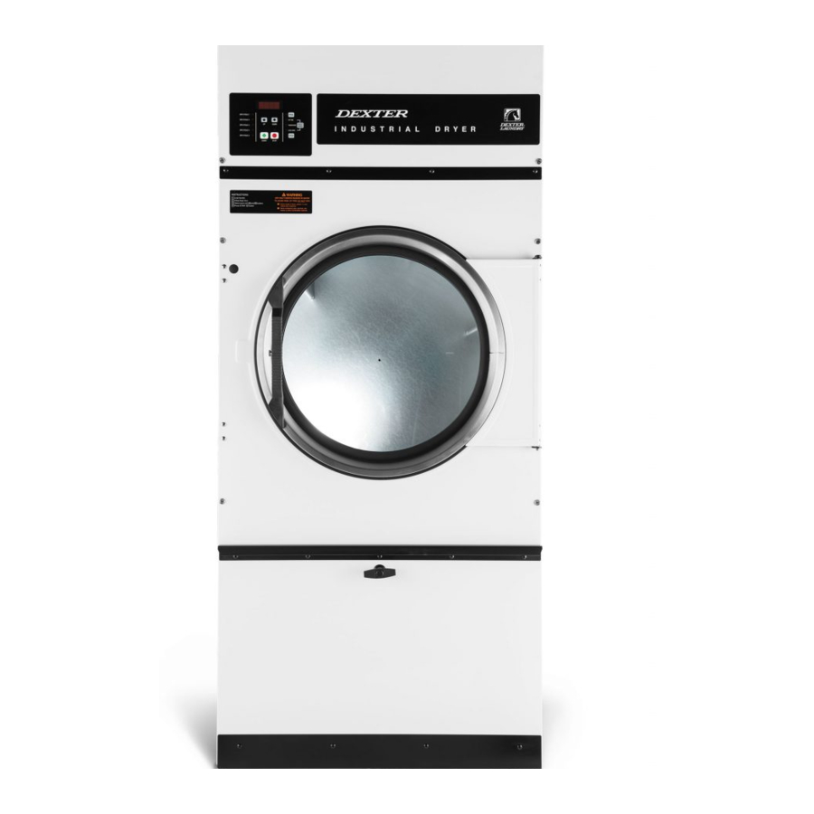
Dexter Laundry T-30 Operators Manual Installation & Operation Instructions
Industrial dryers
on-premise
o-series control, natural gas/lp heated
Hide thumbs
Also See for T-30:
- Operators manual installation & operation instructions (187 pages) ,
- Operator's manual (80 pages) ,
- Original instructions manual (31 pages)
Table of Contents
Advertisement
Available languages
Available languages
INDUSTRIAL DRYERS
MODEL T-30/50/80/120 ON-PREMISE
O-SERIES CONTROL, NATURAL GAS/LP HEATED
The dryer must not be stored or installed where it will be exposed to water and/or weather.
WARNING:
FIRE OR EXPLOSION HAZARD
Failure to follow safety warnings
exactly could result in serious injury,
death or property damage.
– Do not store or use gasoline or other
flammable vapors and liquids in the vicinity of
this or any other appliance.
– WHAT TO DO IF YOU SMELL GAS
• Do not try to light any appliance.
• Do not touch any electrical switch; do not
use any phone in your building.
• Clear the room, building or area of all
occupants.
• Immediately call your gas supplier from a
neighbor's phone. Follow the gas supplier's
instructions.
• If you cannot reach your gas supplier, call
the fire department.
– Installation and service must be performed by
a qualified installer, service agency or the gas
supplier.
Post the following "For Your Safety" caution in a
prominent location:
FOR YOUR SAFETY
Do not store or use gasoline or other flammable
vapors or liquids in the vicinity of this or any
other appliance.
It is important that you read this Manual and retain it
for future reference. For service or replacement parts,
contact the distributor in your area or the manufacturer.
8514-291-001 REV PR PAGE 1
OPERATOR'S MANUAL
INSTALLATION & OPERATION INSTRUCTIONS
Dexter Laundry Inc.
2211 West Grimes Avenue
Fairfield, Iowa 52556
AVERTISSEMENT: Assurez-vouz
de bien suivre les instructions
données dans cette notice pour
réduire au minimum le risque
d'incendie ou d'explosion ou pour
éviter tout dommage matérial,
toute blessure ou la mort.
–
Ne pas entreposer ni utiliser d'essence ni
d'autres vapeurs ou liquides inflammables dans
le voisinage de cet appareil ou de tout autre
appareil.
– QUE FAIRE SI VOUS SENTEZ UNE ODEUR DE GAZ:
• Ne pas tenter d'allumer d'appareil.
• Ne touchez à aucun interrupteur. Ne pas
vous servir des téléphones se trouvant
dans le bâtiment où vous trouvez.
• Évacuez la pièce, le bâtiment ou la zone.
• Appelez immédiatement votre fournisseur
de gaz depuis un voisin. Suivez les
instructions du fournisseur.
• Si vous ne pouvez rejoindre le fournisseur
de gaz, appelez le service des incendies.
– L'installation et l'entretien doivent être assures
par un installateur ou un service d'entretien
qualifie ou par le fournisseur de gaz.
POUR VOTRE SÉCURITÉ
Ne pas ente poser ni utiliser d'essence ni d'autres
vapeurs ou liquides inflammables dans le voisinage
de cet appareil ou de tout autre appareil.
You, the purchaser, must post in a prominent loca-
tion instructions to be followed in the event the user
smells gas. Consult your local gas supplier for pro-
cedure to be followed if the odor of gas is present.
Advertisement
Chapters
Table of Contents

Related Manuals for Dexter Laundry T-30


Summary of Contents for Dexter Laundry T-30
- Page 1 INDUSTRIAL DRYERS MODEL T-30/50/80/120 ON-PREMISE O-SERIES CONTROL, NATURAL GAS/LP HEATED OPERATOR’S MANUAL INSTALLATION & OPERATION INSTRUCTIONS The dryer must not be stored or installed where it will be exposed to water and/or weather. WARNING: AVERTISSEMENT: Assurez-vouz de bien suivre les instructions FIRE OR EXPLOSION HAZARD données dans cette notice pour...
-
Page 2: Table Of Contents
TABLE OF CONTENTS WARNINGS ABOUT USE AND OPERATION ..............3 DRYER SPECIFICATION SHEET ..................4 T-30 DRYER DIMENSIONS .................... 5 T-50 REVERSING DRYER DIMENSIONS ................8 T-80 REVERSING DRYER DIMENSIONS ................ 11 T-120 REVERSING DRYER DIMENSIONS ..............14 INSTALLATION INSTRUCTIONS .................. 17 UNCRATING ...................... -
Page 3: Warnings About Use And Operation
1 WARNINGS ABOUT USE AND OPERATION It is ABSOLUTELY ESSENTIAL that the dryer be grounded to a known earth (zero) ground. This is not only for personal safety, but is necessary for proper operation. DO NOT MODIFY THIS APPLIANCE. KEEP SHIELDS, GUARDS, AND COVERS IN PLACE. These safety devices are provided to protect everyone from injury. -
Page 4: Dryer Specification Sheet
2 DRYER SPECIFICATION SHEET T-30 T-50 T-80 T-120 Capacity Dry Weight Capacity - lb (kg) (13.6) (22.7) (36.3) (54.4) Cylinder Volume - cu ft (L) 11.3 (320) 15.8 (447.4) (651.3) 36.1 (1022.2) Speed Tumbler Speed – RPM 36.5 Motor Size - 60 Hz Standard - hp (kW) (0.38) -
Page 5: 30 Dryer Dimensions
3 T-30 DRYER DIMENSIONS T-30 DRYER DIMENSIONS – FRONT VIEW 8514-291-001 REV PR PAGE 5... - Page 6 T-30 – DRYER DIMENSIONS – SIDE VIEW 8514-291-001 REV PR PAGE 6...
- Page 7 T-30 – DRYER DIMENSIONS – TOP VIEW 8514-291-001 REV PR PAGE 7...
-
Page 8: 50 Reversing Dryer Dimensions
4 T-50 REVERSING DRYER DIMENSIONS T-50 REVERSING DRYER DIMENSIONS – FRONT VIEW 8514-291-001 REV PR PAGE 8... - Page 9 T-50 REVERSING DRYER DIMENSIONS- SIDE VIEW 8514-291-001 REV PR PAGE 9...
- Page 10 T-50 REVERSING DRYER DIMENSIONS - TOP VIEW 8514-291-001 REV PR PAGE 10...
-
Page 11: 80 Reversing Dryer Dimensions
5 T-80 REVERSING DRYER DIMENSIONS T-80 REVERSING DRYER DIMENSIONS – FRONT VIEW 8514-291-001 REV PR PAGE 11... - Page 12 T-80 REVERSING DRYER DIMENSIONS – SIDE VIEW 8514-291-001 REV PR PAGE 12...
- Page 13 T-80 REVERSING DRYER DIMENSIONS – TOP VIEW 8514-291-001 REV PR PAGE 13...
-
Page 14: 120 Reversing Dryer Dimensions
6 T-120 REVERSING DRYER DIMENSIONS T-120 REVERSING DRYER DIMENSIONS – FRONT VIEW 8514-291-001 REV PR PAGE 14... - Page 15 T-120 REVERSING DRYER DIMENSIONS – SIDE VIEW 8514-291-001 REV PR PAGE 15...
- Page 16 T-120 REVERSING DRYER DIMENSIONS – TOP VIEW 8514-291-001 REV PR PAGE 16...
-
Page 17: Installation Instructions
3. With a walking motion, move the dryer forward completely off the wooden skid. Save the skid for future moving of the dryer. 4. T-30/50/80: Using the channel-lock wrench, adjust the leveling legs to align the machine with adjacent units. The T-120 requires shimming to level the dryer. -
Page 18: Make-Up Air
Do not obstruct the flow of combustion and ventilation air. Maintain minimum of 1” (25) clearance between duct and combustible material. Refer to installation label attached to the rear guard of the dryer for other installation information. VERTICAL CLEARANCE DIMENSIONS - TYPICAL 7.2.3 MAKE-UP AIR Adequate make-up air must be supplied to replace air exhausted by dryers on all types of installations. -
Page 19: Gas Requirements
An individual gas shutoff valve is recommended for each dryer and may be required by local code (not supplied). The inlet gas connection to the unit is 1/2 inch [12.7] pipe thread for T-30/50 and 3/4 inch [19.1] for the T-80/T- 120. -
Page 20: Exhaust Installation
For the most efficient operation, it is recommended that no more than 14' (4.3m) of straight (8” (20.3cm) for T-30/50/80, 10 or 12” (25.4 or 30.5cm) for T-120) diameter pipe be used with two right angle elbows. When more than two elbows are used, 2' (61cm) of straight pipe should be removed for each additional elbow. -
Page 21: Dryer Shutdown
A. First, review and comply with the “WARNINGS ABOUT USE AND OPERATION” found on the inside front cover of this manual. Be sure the electrical power supply is connected correctly. The dryer MUST be properly grounded. B. Make sure all gas supply lines are purged of air. Close the main gas shut-off valve and wait for five minutes before turning the valve back on. -
Page 22: End Of Cycle
END OF CYCLE A tone will sound (if programmed) and the display will indicate that the cycle has ended. Immediately remove contents of dryer. Leave the door open when the machine is not in use. 9 PROGRAMMING / MANAGEMENT VIEW ENTER PROGRAMMING MODE 9.1.1 In the cycle selection screen, scroll to Management View at the beginning of the cycle list... -
Page 23: Dryer Error Messages
12 DRYER ERROR MESSAGES The O-Series dryer control reacts to various abnormal conditions by displaying an Error message. These messages usually contain the “Error” text, and then a general description of the message. Below is a listing of Error messages separated by each potential displayed message in bold face. Each is followed by: Condition that creates the displayed message on the control •... - Page 24 Action When detected, the control turns off the motor and the heating relay. There is no delay in the action once the criteria are met. Exit The machine will not start and the Error Code will continue to be displayed until the condition is no longer present.
- Page 25 Exit The machine will not start and the Error Code will continue to be displayed until the prompt is followed to Reset the Error Code and return the Machine to Idle Mode. If the prompt to Reset is not available, power must be cycled to the machine to reset the error.
- Page 26 Action When detected, the control turns off the motor and the heating relay. There is no delay in the action once the criteria are met. The machine control checks for this condition when power is cycled and before starting every machine cycle. Exit The machine will not start and the Error Code will continue to be displayed until the condition no longer exists and the prompt is followed to Reset the Error...
- Page 27 Exit The machine will not start and the Error Code will continue to be displayed until the condition no longer exists and the prompt is followed to Reset the Error Code and return the Machine to Idle Mode. DRIVE INTERNAL Condition This error occurs when the control receives a message that the drive has experienced an internal error.
- Page 28 AUTODRY OOR LOW Condition This error occurs when the machine control sees output from the RMC sensor (secondary) board that is out-of-range at 0V or lower. Action When detected there is a delay of 5 minutes before the error is active. Once active, the control will display the “AUTODRY OOR LOW”...
-
Page 29: Servicing The Dryer
13 SERVICING THE DRYER CAUTION: Label all wires prior to disconnection when servicing controls. Wiring errors can cause improper and dangerous operation. Verify proper operation after servicing. ATTENTION: Au moment de l'entretien des commandes, étiquetez tous les fils avant de les débrancher. Des erreurs de câblage peuvent entraîner un fonctionnement inadéquat et dangereux. -
Page 30: Preventive Maintenance Instructions
9822-026-002 9822-026-001 9822-031-002 9822-033-001 For service and parts information, contact your local Dexter agent. If a Dexter agent is not available, contact Dexter Laundry, Inc. directly as listed below: Mailing Address: 2211 West Grimes Avenue Phone: 1-800-524-2954 Fairfield, IA 52556 Website: www.dexter.com... - Page 31 SÉCHEUSES INDUSTRIELLES MODÈLE T-30/50/80/120 SUR SITE COMMANDE DE LA SÉRIE O, CHAUFFAGE AU GAZ NATUREL/GPL MANUEL DE L’UTILISATEUR INSTRUCTIONS D’INSTALLATION ET D’UTILISATION La sécheuse ne doit pas être entreposée ni installée dans des endroits où elle risque d’être exposée à l’eau ou aux conditions climatiques.
- Page 32 TABLE DES MATIÈRES 15 AVERTISSEMENTS RELATIFS À L’UTILISATION ET AU FONCTIONNEMENT 16 FICHE TECHNIQUE DE LA SÉCHEUSE 17 DIMENSIONS DE LA SÉCHEUSE T-30 18 DIMENSIONS DE LA SÉCHEUSE À INVERSEMENT T-50 19 DIMENSIONS DE LA SÉCHEUSE À INVERSEMENT T-80 20 DIMENSIONS DE LA SÉCHEUSE À INVERSEMENT T-120 21 INSTRUCTIONS D’INSTALLATION...
-
Page 33: Avertissements Relatifs À L'utilisation Et Au Fonctionnement
15 AVERTISSEMENTS RELATIFS À L’UTILISATION ET AU FONCTIONNEMENT Il est ABSOLUMENT NÉCESSAIRE de mettre la sécheuse à la terre en la raccordant à une masse de terre (zéro) connue. Cette mesure assure non seulement la sécurité personnelle, mais elle est également nécessaire pour le bon fonctionnement de la machine. -
Page 34: Fiche Technique De La Sécheuse
16 FICHE TECHNIQUE DE LA SÉCHEUSE T-30 T-50 T-80 T-120 Capacité Capacité de poids sec - lb (kg) (13,6) (22,7) (36,3) (54,4) Volume du cylindre - pi³ (L) 11,3 (320) 15,8 (447,4) (651,3) 36,1 (1022,2) Vitesse Vitesse du tambour - tr/min 36,5 Taille du moteur - Modèle 60 Hz standard - hp (kW) -
Page 35: Dimensions De La Sécheuse
17 DIMENSIONS DE LA SÉCHEUSE T-30 RACCORDEMENT AU GAZ (À L’ARRIÈRE DE LA MACHINE) PATTES DE MISE À NIVEAU MONTRÉES EN HAUTEUR MINIMUM, POUR UNE HAUTEUR MAXIMUM AJOUTER 1 PO [25] DIMENSIONS DE LA SÉCHEUSE T-30 - VUE DE FACE 8514-291-001 REV PR PAGE 35... - Page 36 RACCORDEMENT ÉLECTRIQUE RACCORDEMENT À L’EAU DE 3/4 PO [19] (MODÈLE EN OPTION) DIMENSIONS DE LA SÉCHEUSE - T-30 - VUE DE CÔTÉ 8514-291-001 REV PR PAGE 36...
- Page 37 RACCORDEMENT ÉLECTRIQUE RACCORDEMENT AU GAZ CONDUIT D’ÉVACUATION DE 8 PO [203] RACCORDEMENT À L’EAU (MODÈLE EN OPTION) DIMENSIONS DE LA SÉCHEUSE - T-30 - VUE DE DESSUS 8514-291-001 REV PR PAGE 37...
-
Page 38: Dimensions De La Sécheuse À Inversement
18 DIMENSIONS DE LA SÉCHEUSE À INVERSEMENT T-50 RACCORDEMENT AU GAZ (À L’ARRIÈRE DE LA MACHINE) PATTES DE MISE À NIVEAU MONTRÉES EN HAUTEUR MINIMUM, POUR UNE HAUTEUR MAXIMUM AJOUTER 1 PO [25] DIMENSIONS DE LA SÉCHEUSE À INVERSEMENT T-50 - VUE DE FACE 8514-291-001 REV PR PAGE 38... - Page 39 RACCORDEMENT ÉLECTRIQUE RACCORDEMENT À L’EAU DE 3/4 PO [19] (MODÈLE EN OPTION) DIMENSIONS DE LA SÉCHEUSE À INVERSEMENT T-50 - VUE DE CÔTÉ 8514-291-001 REV PR PAGE 39...
- Page 40 RACCORDEMENT À L’EAU (MODÈLE EN OPTION) RACCORDEMENT ÉLECTRIQUE RACCORDEMENT AU GAZ CONDUIT D’ÉVACUATION DE 8 PO [203] DIMENSIONS DE LA SÉCHEUSE À INVERSEMENT T-50 - VUE DE DESSUS 8514-291-001 REV PR PAGE 40...
-
Page 41: Dimensions De La Sécheuse À Inversement
19 DIMENSIONS DE LA SÉCHEUSE À INVERSEMENT T-80 RACCORDEMENT AU GAZ (À L’ARRIÈRE DE LA MACHINE) PATTES DE MISE À NIVEAU MONTRÉES EN HAUTEUR MINIMUM, POUR UNE HAUTEUR MAXIMUM AJOUTER 1 PO [25] DIMENSIONS DE LA SÉCHEUSE À INVERSEMENT T-80 - VUE DE FACE 8514-291-001 REV PR PAGE 41... - Page 42 RACCORDEMENT À L’EAU DE 3/4 PO [19] RACCORDEMENT ÉLECTRIQUE (MODÈLE EN OPTION) DIMENSIONS DE LA SÉCHEUSE À INVERSEMENT T-80 - VUE DE CÔTÉ 8514-291-001 REV PR PAGE 42...
- Page 43 RACCORDEMENT À L’EAU RACCORDEMENT (MODÈLE EN OPTION) ÉLECTRIQUE RACCORDEMENT CONDUIT D’ÉVACUATION AU GAZ DE 8 PO [203] DIMENSIONS DE LA SÉCHEUSE À INVERSEMENT T-80 - VUE DE DESSUS 8514-291-001 REV PR PAGE 43...
-
Page 44: Dimensions De La Sécheuse À Inversement T-120
20 DIMENSIONS DE LA SÉCHEUSE À INVERSEMENT T-120 RACCORDEMENT AU GAZ (À L’ARRIÈRE DE LA MACHINE) DESSUS RETIRÉ DIMENSIONS DE LA SÉCHEUSE À INVERSEMENT T-120 - VUE DE FACE 8514-291-001 REV PR PAGE 44... - Page 45 RACCORDEMENT ÉLECTRIQUE RACCORDEMENT À L’EAU DE 3/4 PO [19] (MODÈLE EN OPTION) DIMENSIONS DE LA SÉCHEUSE À INVERSEMENT T-120 - VUE DE CÔTÉ 8514-291-001 REV PR PAGE 45...
- Page 46 RACCORDEMENT ÉLECTRIQUE RACCORDEMENT À L’EAU (MODÈLE EN OPTION) RACCORDEMENT AU GAZ CONDUIT D’ÉVACUATION DE 10 PO [254] DIMENSIONS DE LA SÉCHEUSE À INVERSEMENT T-120 - VUE DE DESSUS 8514-291-001 REV PR PAGE 46...
-
Page 47: Instructions D'installation
Conservez la palette pour le déplacement ultérieur de la sécheuse. 8. T-30/50/80 : À l’aide de la pince multiprise, ajustez les pattes de mise à niveau afin d’aligner la machine avec les unités adjacentes. Le modèle T-120 nécessite un calage afin de mettre la sécheuse à niveau. -
Page 48: Air D'appoint
*Les unités peuvent être installées en contact direct avec une sécheuse adjacente, à condition qu’il soit possible d’ouvrir les portes de service supérieures et inférieures. N’obstruez pas le flux de combustion et d’air de ventilation. Maintenez un écart minimum de 1 po (25) entre le tuyau et le matériau combustible. Consultez l’étiquette d’installation apposée à... -
Page 49: Important : Suppresseurs De Surtension Transitoire
Il est conseillé d’installer un robinet d’arrêt de gaz individuel pour chaque sécheuse, ce qui peut être requis par le Code local (non fourni). Le raccord de gaz d’alimentation à l’unité dispose d’un filetage de 1/2 po [12,7] pour le modèle T-30/50 et de 3/4 po [19,1], pour le modèle T-80/T-120. -
Page 50: Installation De L'évacuation
14 pi (4,3 m) de tuyau droit de 8 po (20,3 cm) de diamètre pour les modèles T-30/50/80 ou de 10 po ou 12 po (25,4 cm ou 30,5 cm) de diamètre, pour le modèle T-120 et deux coudes à angle droit. -
Page 51: Allumage De La Sécheuse (Allumage Transistorisé)
REMARQUE : Un conduit de faible diamètre entraînera une restriction du débit d’air; un conduit de grand diamètre réduira la vitesse de l’air, ce qui contribuera dans les deux cas à une accumulation de charpies. Une porte d’inspection doit être fournie pour le nettoyage périodique du conduit principal. REMARQUE : La CONTRE-PRESSION STATIQUE maximum doit être de 0,3 po de colonne d’eau (7,6 mm de colonne d’eau) à... -
Page 52: Fin De Cycle
22.1.3 Choisir le cycle de séchage. Choisissez le cycle approprié au type de charge en lavage. Utilisez les touches « HAUT » et « BAS » pour changer le cycle affiché au cycle désiré et appuyez sur le bouton Entrée pour le sélectionner. -
Page 53: 25 Détection De Surchauffe
25 DÉTECTION DE SURCHAUFFE Toutes les sécheuses de la série O sont équipées d’un système de détection de surchauffe qui détecte les températures anormalement élevées. Si des températures élevées sont détectées, l’écran de contrôle affiche OVERHEAT TEMPERATURE DETECTED et une alarme retentit. Si la porte de chargement est fermée, les modèles à... - Page 54 Sortie La machine ne démarrera pas et le code d’erreur restera affiché tant que la situation persiste. Une fois la situation réglée, la machine ne démarrera toujours pas et le code d’erreur restera affiché jusqu’à ce que l’utilisateur réponde à l’invite de réinitialiser l’erreur et de remettre la machine en mode veille.
- Page 55 PROX SENSOR OUT OF RANGE Condition Cette erreur se produit lorsque la commande de la machine détecte un signal de sortie du détecteur de proximité hors de la plage acceptable pour le modèle de machine à laver ou de sécheuse en question en fonctionnement à vitesse normale.
- Page 56 MODEL JUMPER/ DRIVE SIZE Condition Cette erreur se produit lorsque les raccords du cavalier à la terre (borne 7) de l’en-tête du cavalier du modèle ne correspondent pas au code de taille du VFD. Action Une fois détectée, la commande éteint le moteur et le relais de chauffage. L’action se produit sans délai une fois les critères remplis.
- Page 57 Sortie La machine ne démarrera pas et le code d’erreur restera affiché tant que la situation persiste et jusqu’à ce que l’utilisateur réponde à l’invite de réinitialiser le code d’erreur et de remettre la machine en mode veille. DRIVE OVERLOAD Condition Cette erreur se produit lorsque la commande reçoit un message indiquant que l’entraînement a été...
- Page 58 DRIVE ENABLE Condition Cette erreur se produit lorsque la commande détecte un message indiquant que le circuit VFD activé n’est pas fermé. Action Une fois détectée, la commande éteint le moteur et le relais de chauffage. L’action se produit sans délai une fois les critères remplis. Sortie La machine ne démarrera pas et le code d’erreur restera affiché...
-
Page 59: Entretien De La Sécheuse
Sortie La machine ne démarrera pas et le code d’erreur restera affiché tant que la situation persiste. Une fois la situation réglée, la machine ne démarrera toujours pas et le code d’erreur restera affiché jusqu’à ce que l’utilisateur réponde à l’invite de réinitialiser l’erreur et de remettre la machine en mode veille. -
Page 60: Instructions D'entretien Préventif
9822-031-002 9822-033-001 Pour obtenir des renseignements relatifs à l’entretien et aux pièces, communiquez avec votre agent Dexter local. Si aucun agent Dexter n’est disponible, communiquez directement avec Dexter Laundry, Inc. par l’un des moyens énumérés ci-dessous : Adresse postale : 2211 West Grimes Avenue Téléphone :...
Need help?
Do you have a question about the T-30 and is the answer not in the manual?
Questions and answers