Dexter Laundry T-30X2 Installation & Operation Instructions
Industrial dryer
Hide thumbs
Also See for T-30X2:
Table of Contents
Advertisement
Quick Links
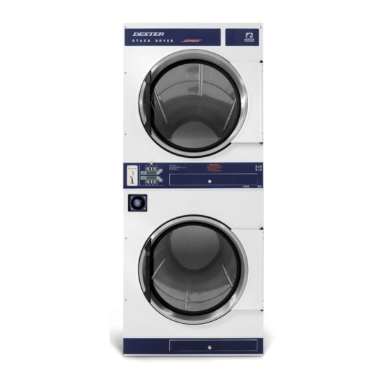
INDUSTRIAL DRYER
MODEL T-30X2 ON-PREMISE
B-SERIES CONTROL, ELECTRIC-HEATED
INSTALLATION & OPERATION INSTRUCTIONS
The dryer will operate correctly in ambient temperatures of 5°C to 45°C, in relative humidity
up to 50% at 40°C and above 50% when below 40°C, and at altitudes up to 1000m above
sea level, must be transported and stored from -40°C to 140°C, and has been packaged to
prevent damage from humidity, vibration, and shock. Take measures to avoid harmful
effects of occasional condensation.
Post the following "For Your Safety" cautions in a prominent location:
Do not store or use petrol or other flammable vapours and liquids or dry cleaning
solvents in the vicinity of this or any other appliance.
THIS MACHINE IS FOR DRYING ONLY FABRICS WASHED IN WATER. To avoid
possibility of fire, including spontaneous combustion, do not dry oiled floor mops, items
containing foam rubber or similarly textured rubberlike materials or any material on
which you have used a cleaning solvent or which contains flammable liquids or solids
(such as petrol, kerosene, waxes, etc.) Fabric softeners, or similar products, should be
used per the fabric softener instructions. Remove all objects from pockets such as
lighters and matches.
WARNING – Risk of Fire
Clothes dryer installation must be performed by a qualified installer.
Install the clothes dryer according to the manufacturer's instructions and local codes.
Do not install a clothes dryer with flexible plastic venting materials. If flexible metal (foil type)
duct is installed, use duct that has been investigated and found acceptable for use with
clothes dryers. Flexible venting materials are known to collapse, be easily crushed, and trap
lint. These conditions will obstruct clothes dryer airflow and increase the risk of fire.
To reduce the risk of severe injury or death, follow all installation instructions.
This appliance can be used by children aged from 8 years and above and persons with
reduced physical, sensory or mental capabilities, or lack of experience and knowledge, if
they have been given supervision or instruction concerning use of the appliance in a safe
way and understand the hazards involved. Children shall not play with the appliance.
Cleaning and user maintenance shall not be made by children without supervision.
Children of less than 3 years should be kept away unless continuously supervised.
It is important that you read this Manual and retain it for future reference. For service
or replacement parts, contact the distributor in your area or the manufacturer:
8514-211-001 REV D PAGE 1
Original Instructions
For GB & IE
OPERATOR'S MANUAL
FOR YOUR SAFETY
FOR YOUR SAFETY
Dexter Laundry, Inc.
2211 West Grimes Avenue
Fairfield, Iowa 52556, USA
Advertisement
Table of Contents

Related Manuals for Dexter Laundry T-30X2


Summary of Contents for Dexter Laundry T-30X2
- Page 1 INDUSTRIAL DRYER Original Instructions MODEL T-30X2 ON-PREMISE For GB & IE B-SERIES CONTROL, ELECTRIC-HEATED OPERATOR’S MANUAL INSTALLATION & OPERATION INSTRUCTIONS The dryer will operate correctly in ambient temperatures of 5°C to 45°C, in relative humidity up to 50% at 40°C and above 50% when below 40°C, and at altitudes up to 1000m above sea level, must be transported and stored from -40°C to 140°C, and has been packaged to...
-
Page 2: Table Of Contents
TABLE OF CONTENTS Page No. Dryer Dimensions (Figure 1)................4 Uncrating ....…................... 5 Dryer Installation (Figure 2)................6 Dryer Exhaust System (Figure 3)............... 10 Dryer Shutdown....................10 Touch Pad Layout (Figure 4)................11 Dryer Default Settings..................12 Dryer Default Codes..................12 Touch Pad Description.................. - Page 3 WARNINGS ABOUT USE AND OPERATION continued THIS DRYER IS EQUIPPED WITH A MANUALLY RESETTABLE OVER- TEMPERATURE THERMOSTAT located on the top of the exhaust duct beside the motor. Should the dryer cease to heat, reset the thermostat by rotating the lever bracket clockwise.
-
Page 4: Dryer Dimensions (Figure 1)
FIGURE 1 Dryer Dimensions - inches (mm) -
Page 5: Uncrating
INSTALLATION AND OPERATING INSTRUCTIONS Note: A forklift, or a hand pallet truck or jack, must lift the dryer and only from the front or rear of the dryer with the dryer bolted to the pallet and supported the full length of the dryer. UNCRATING AND PLACING DRYER Tools Required: 3/4"... -
Page 6: Dryer Installation (Figure 2)
III. Back 18 in. (457 mm) (Certified for 6 in. (150 mm) clearance; however, 18 in. (457 mm) clearance is necessary behind the motors to allow servicing and maintenance.) IV. Front 48 in. (1220 mm) to allow use of dryer. V. - Page 7 The source of make-up air should be located sufficiently away from the dryers to allow an even airflow to the air intakes of all dryers. Multiple openings should be provided. The operation of this appliance may affect the operation of gas appliances, which take their air for safe combustion from the same room.
- Page 8 utilization category defined in the product standard as appropriate for on-load switching of motors or other inductive loads; The supply disconnecting devices must a. provide a means allowing the supply disconnecting devices to be locked in the OFF position; b. be mounted 0.7m to 1.7m above the floor, within 2 m from the dryer, and within 8 m from the operator position;...
- Page 9 From an operational standpoint, incorrect or inadequate exhausting can cause a cycling of the high limit thermostat, which shuts off the heating elements and results in inefficient drying. The exhaust duct connection near the top of the dryer will accept an 8 in. (200 mm) round duct.
-
Page 10: Dryer Exhaust System (Figure 3)
the individual dryer ducts. The main duct can be rectangular or round, provided adequate airflow is maintained. For each individual dryer, the total exhausting (main discharge duct plus duct outlet from the dryer) should not exceed the equivalent of 14 ft. -
Page 11: Touch Pad Layout (Figure 4)
-11-... -
Page 12: Dryer Default Settings
DRYER CONTROLLER FACTORY DEFAULT PROGRAM SETTINGS COOL DOWN TOTAL CYCLE DRYING TIME TIME TEMPERATURE DRYER LOAD CYCLE (MINUTES) (MINUTES) Towels, pads, heavy cotton Sheets, blended materials Cotton Synthetic materials Blended materials DRYER FAULT CODES FAULT FAULT ACTION DESCRIPTION Dryer stops and “F1” flashes on the 4-digit display. Shorted When short circuit on sensor input is removed, “LOAd”... -
Page 13: Touch Pad Description
TOUCH PAD DESCRIPTION INDICATOR LIGHTS (L.E.D.s) Description Cycle (1 through 5) These L.E.D.s are on solid when a particular cycle is chosen for operation or programming. Heat Relay This L.E.D. is part of the 4-digit numeric display and will be on solid during the drying part of a cycle when the heat relay does not need to be on. - Page 14 SWITCHES (Pushbuttons) - continued Description This touch pad switch will stop the dryer during a dry cycle without clearing the present drying cycle if pressed once. If pressed and released twice, Stop consecutively, the present dry cycle will be cleared. This touch pad switch will start the operation of a dry cycle if pressed and released once.
-
Page 15: Operating Instructions
OPERATING INSTRUCTIONS Maximum Load Capacity: 13.6 kg (30 Pounds) Dry Weight per Drying Cylinder. To dry a load of items, you must choose one of the five-programmed dry cycles. Each of these five dry cycles may be modified in two different ways to match your load. Please refer to the “Permanent Dryer Controller Programming”... - Page 16 When the time decrements to zero, the dryer controller display will flash the word “donE” and the end of cycle tone will sound. At that point, the wrinkle free cycle will automatically begin. This cycle will wait two minutes, if the door is not opened or the STOP touch pad key on the dryer controller is not pressed, and then rotate the cylinder for 10 seconds and stop.
-
Page 17: Programming Instructions
TEMPORARY DRYER CONTROLLER PROGRAMMING The temporary programming mode will allow the change of the stored dry cycle settings in the dryer controller for one complete dry cycle. After the dry cycle is complete, the default settings that existed before the temporary change are restored. The temporary dry cycle can be stopped and cleared at any time during the dry cycle operation. - Page 18 total dry times available (1 through 60 minutes). This displayed dry time includes the cool down time along with the heated time. To not change the total dry time, do not press the arrow keys to change the total dry time. 5) Press and release the SELECT/ENTER key.
- Page 19 The following procedure will show you how to temporarily modify the existing dry cycle 1 program for one cycle of drying. It is based on the assumption that the factory defaults have not been permanently changed. If they have been changed, the steps of this procedure will be the same, but the values that are displayed will be different.
- Page 20 If you press the START touch pad key on the dryer controller, the controller display will change from the number “5” to the number “45” and dry cycle 1 will begin. PERMANENT DRYER CONTROLLER PROGRAMMING The permanent programming mode will allow the change of the stored dry cycle settings in the dryer controller until the operator physically changes them again.
- Page 21 time along with the heated time. To not change the total dry time, do not press the arrow keys. Go to the next step. 7) Press and release the SELECT/ENTER key. Once this key is pressed and released, the dry time L.E.D. will switch off, the dry cycle L.E.D. and programming L.E.D. will remain on, and the temperature L.E.D.
- Page 22 The following procedure will show you how to permanently modify the existing dry cycle 1 program for one cycle of drying. It is based on the assumption that the factory defaults have not been permanently changed. If they have been changed, the steps of this procedure will be the same, but the values that are displayed will be different.
- Page 23 11) Press and release the STOP touch pad key. The dry time L.E.D. will remain on and the programming L.E.D. will switch off. The dryer controller display will change to the word “LOAd”. The dryer is now ready for the new modified dry cycle to start. This modified dry cycle 1 program will remain in the dryer controller memory until the default settings push button is pressed.
-
Page 24: Servicing Dryer
SERVICING THE DRYER Note: A key with the markings “6324” is provided for service access to controller and another key with markings “6101” is provided for service access to the lint screens, both by a qualified person. These keys should be stored in a secure place away from the dryer. Routine Non-Technical Maintenance and Cleaning: DAILY (WARNING: Do not operate the dryer without the lint screen in place.) Use service key to gain access to the lint screen compartment. - Page 25 9040-073-009 LINT SCREEN FILTER 9555-057-002 For service and parts information contact your local Dexter agent. If a Dexter agent is not available, contact Dexter Laundry, Inc. directly as listed below: Mailing Address: 2211 West Grimes Avenue Phone: 1-800-524-2954 Fairfield, IA 52556 Website: www.dexter.com...
- Page 26 Machinery Directive on machinery safety, 2006/42/EC Conforming Industrial Drying System Machinery: Model Numbers: DN30X2E, DN0030E, DN0050E, DN0080E, DNS030E Serial Numbers: Manufacturer: Dexter Laundry, Inc. 2211 West Grimes Avenue Fairfield, IA 52556 USA Harmonised EN ISO 12100:2010 Safety of machinery. General principles for Standards design.
- Page 27 WITH COUNCIL DIRECTIVE 2004/108/EC Directive: Electromagnetic Compatibility Directive 2004/108/EC Conforming Industrial Drying System Machinery: Model Numbers: DN30X2E, DN0030E, DN0050E, DN0080E, DNS030E Manufacturer: Dexter Laundry, Inc. 2211 West Grimes Avenue Fairfield, IA 52556 USA Harmonised EN 55014-1:2006/A2:2011 Electromagnetic compatibility. Requirements Standards CISPR 14-1:2005/A2:2011...
- Page 28 Declaration of Noise Emission The Dexter Laundry Industrial Drying System Models Sound Pressure Levels per EN ISO 11202 as measured on similarly constructed models are as follows: Model DCBD30KC-64FN Operating Idle (Operator Position) 61 dB (A) 54 dB (A) (Bystander Position)
Need help?
Do you have a question about the T-30X2 and is the answer not in the manual?
Questions and answers