Dexter Laundry T-30 Operators Manual Installation & Operation Instructions
Commercial dryer vended x-series touch control, natural gas/lp heated
Hide thumbs
Also See for T-30:
- Operators manual installation & operation instructions (187 pages) ,
- Operator's manual (80 pages) ,
- Original instructions manual (31 pages)
Table of Contents
Advertisement
Quick Links
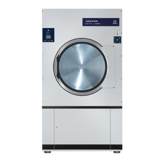
COMMERCIAL DRYER
MODEL T-30, T-50, T-80, T-120 VENDED
X-SERIES TOUCH CONTROL, NATURAL GAS/LP HEATED
The dryer must not be stored or installed where it will be exposed to water and/or weather.
WARNING:
FIRE OR EXPLOSION HAZARD
Failure to follow safety warnings exactly could
result in serious injury, death or property damage.
– Do not store or use gasoline or other flammable vapors and
liquids in the vicinity of this or any other appliance.
– WHAT TO DO IF YOU SMELL GAS
• Do not try to light any appliance.
• Do not touch any electrical switch; do not use any phone
in your building.
• Clear the room, building or area of all occupants.
• Immediately call your gas supplier from a neighbor's
phone. Follow the gas supplier's instructions.
• If you cannot reach your gas supplier, call the fire
department.
– Installation and service must be performed by a qualified
installer, service agency or the gas supplier.
Post the following "For Your Safety" caution in a
prominent location:
FOR YOUR SAFETY
Do not store or use gasoline or other flammable
vapors or liquids in the vicinity of this or any other
appliance.
It is important that you read this Manual and retain it
for future reference. For service or replacement parts,
contact
the
distributor
manufacturer.
THIS MACHINE IS FOR DRYING ONLY FABRICS CLEANED IN WATER.
To avoid possibility of fire, including spontaneous combustion, do not dry oiled floor mops, items containing foam
rubber or similarly textured rubberlike materials or any material on which you have used a cleaning solvent or which
contains flammable liquids or solids (such as petrol, kerosene, waxes, etc.) Fabric softeners, or similar products,
should be used per the fabric softener instructions. Remove all objects from pockets such as lighters and matches.
This appliance can be used by children aged from 8 years and above and persons with reduced physical, sensory
or mental capabilities or lack of experience and knowledge if they have been given supervision or instruction
concerning use of the appliance in a safe way and understand the hazards involved. Children shall not play with
the appliance. Cleaning and user maintenance shall not be made by children without supervision. Children of less
than 3 years should be kept away unless continuously supervised.
8514-308-001 REV PR page 1
OPERATOR'S MANUAL
INSTALLATION & OPERATION INSTRUCTIONS
in
your
area
or
FOR YOUR SAFETY
Dexter Laundry, Inc.
2211 W. Grimes
Fairfield, Iowa 52556
AVERTISSEMENT. Assurez-vous de bien suivre
les instructions données dans cette notice pour
réduire au minimum le risque d'incendie ou
d'explosion ou pour éviter tout dommage matérial,
toute blessure ou la mort.
– Ne pas entreposer ni utiliser d'essence ni d'autres vapeurs
ou liquides inflammables à proximité de cet appareil ou de tout
autre appareil.
– QUE FAIRE SI VOUS SENTEZ UNE ODEUR DE GAZ:
• Ne pas tenter d'allumer d'appareils.
• Ne touchez à aucun interrupteur. Ne pas vous server des
téléphones se trouvant dans le bâtiment.
• Évacuez la pièce, le bâtiment ou la zone.
• Appelez immédiatement votre fournisseur de gaz depuis
un voisin. Suivez les instructions du fournisseur.
• Si vous ne pouvez rejoindre le fournisseur de gaz,
appelez le service des incendies.
– L'installation et l'entretien doivent être assurés par un
installateur ou un service d'entretien qualifié ou par le
fournisseur de gaz.
POUR VOTRE SÉCURITÉ
Ne pas enteposer ni utiliser d'essence ni d'autres
vapeurs ou liquides inflammables à proximité
de cet appareil ou de tout autre appareil.
You, the purchaser, must post in a prominent location
instructions to be followed in the event the user smells
gas. Consult your local gas supplier for procedure to
the
be followed if the odor of gas is present.
Advertisement
Table of Contents

Related Manuals for Dexter Laundry T-30


Summary of Contents for Dexter Laundry T-30
- Page 1 COMMERCIAL DRYER MODEL T-30, T-50, T-80, T-120 VENDED X-SERIES TOUCH CONTROL, NATURAL GAS/LP HEATED OPERATOR’S MANUAL INSTALLATION & OPERATION INSTRUCTIONS The dryer must not be stored or installed where it will be exposed to water and/or weather. WARNING: AVERTISSEMENT. Assurez-vous de bien suivre les instructions données dans cette notice pour...
-
Page 2: Table Of Contents
WARNINGS ABOUT USE AND OPERATION ............3 SPECIFICATIONS ....................5 DIMENSIONS ....................10 T-30 DRYER DIMENSIONS - FRONT VIEW ............ 10 T-30 DRYER DIMENSIONS - SIDE VIEW ............11 T-30 DRYER DIMENSIONS - TOP VIEW ............12 T-50 DRYER DIMENSIONS- FRONT VIEW ............. 13 T-50 DRYER DIMENSIONS - SIDE VIEW ............ -
Page 3: Warnings About Use And Operation
1 WARNINGS ABOUT USE AND OPERATION DO NOT MODIFY THIS APPLIANCE. KEEP SHIELDS, GUARDS, AND COVERS IN PLACE. These safety devices are provided to protect everyone from injury. WARNING: Do not stop dryer before end of cycle time unless all items are quickly removed and spread out to dissipate heat. - Page 4 Means that care is required to avoid causing a fire by igniting flammable material. 8514-308-001 REV PR page 4...
-
Page 5: Specifications
2 SPECIFICATIONS 30 lb. Commercial Dryer: T-30 - DC0030N_-15ET_X (60 Hz), DC0030N_-39AT_X (50 Hz) Cabinet Height 72 1/4” 1835 mm. (Assumes minimum leveling leg adjustment) Cabinet Width 31 1/2” 800 mm. Cabinet Depth 41 3/4” 1058 mm. Floor to Bottom of Door 28 3/4”... - Page 6 SPECIFICATIONS 50 lb. Commercial Dryer: T-50 - DC0050N_-15ET_X (60 Hz), DC0050N_-39AT_X (50 Hz) Cabinet Height 72 1/4” 1835 mm. (Assumes minimum leveling leg adjustment) Cabinet Width 34 1/2” 875 mm. Cabinet Depth 48” 1218 mm. Floor to Bottom of Door 27 1/4”...
- Page 7 SPECIFICATIONS 80 lb. Commercial Dryer: T-80 Non-Rev Tumbler - DC0080N_-15ET_X (60 Hz), DC0080N_-39AT_X (50 Hz) Cabinet Height 75 3/4” 1924 mm. (Assumes minimum leveling leg adjustment) Cabinet Width 38 1/2” 978 mm. Cabinet Depth 51 3/4” 1313 mm. Floor to Bottom of Door 29 1/4”...
- Page 8 SPECIFICATIONS 80 lb. Commercial Dryer: T-80 Reversing Tumbler DC0080N_-10ET_R (60 Hz), DC0080N_-39AT_R (50 Hz) Cabinet Height 75 3/4” 1924 mm. (Assumes minimum leveling leg adjustment) Cabinet Width 38 1/2” 978 mm. Cabinet Depth 51 3/4” 1313 mm. Floor to Bottom of Door 29 1/4”...
- Page 9 SPECIFICATIONS 120 lb. Commercial Dryer: T-120 Reversing Tumbler DC0120N_-10EC_R (60 Hz), DC0120N_-39AC_R (50 Hz) Cabinet Height 85 5/16” 2167 mm. Cabinet Width 46 3/4” 1187 mm. Cabinet Depth 60 3/16” 1528 mm. Floor to Bottom of Door 34” 864 mm. Door Opening 30”...
-
Page 10: Dimensions
3 DIMENSIONS 3.1 T-30 DRYER DIMENSIONS - FRONT VIEW 8514-308-001 REV PR page 10... -
Page 11: Dryer Dimensions - Side View
3.2 T-30 DRYER DIMENSIONS - SIDE VIEW 8514-308-001 REV PR page 11... -
Page 12: Dryer Dimensions - Top View
3.3 T-30 DRYER DIMENSIONS - TOP VIEW 8514-308-001 REV PR page 12... -
Page 13: Dryer Dimensions- Front View
3.4 T-50 DRYER DIMENSIONS- FRONT VIEW 8514-308-001 REV PR page 13... -
Page 14: Dryer Dimensions - Side View
3.5 T-50 DRYER DIMENSIONS - SIDE VIEW 8514-308-001 REV PR page 14... -
Page 15: Dryer Dimensions - Top View
3.6 T-50 DRYER DIMENSIONS - TOP VIEW 8514-308-001 REV PR page 15... -
Page 16: Dryer Dimensions- Front View
3.7 T-80 DRYER DIMENSIONS- FRONT VIEW 8514-308-001 REV PR page 16... -
Page 17: Dryer Dimensions - Side View
3.8 T-80 DRYER DIMENSIONS - SIDE VIEW 8514-308-001 REV PR page 17... -
Page 18: Dryer Dimensions - Top View
3.9 T-80 DRYER DIMENSIONS - TOP VIEW 8514-308-001 REV PR page 18... -
Page 19: T-120 Dryer Dimensions- Front View
3.10 T-120 DRYER DIMENSIONS- FRONT VIEW 8514-308-001 REV PR page 19... -
Page 20: T-120 Dryer Dimensions - Side View
3.11 T-120 DRYER DIMENSIONS - SIDE VIEW 8514-308-001 REV PR page 20... -
Page 21: T-120 Dryer Dimensions - Top View
3.12 T-120 DRYER DIMENSIONS - TOP VIEW 8514-308-001 REV PR page 21... -
Page 22: Installation Instructions
4 INSTALLATION INSTRUCTIONS 4.1 UNCRATING AND PLACING DRYER Tools Required: 3/4" (19 mm) hex socket & ratchet driver, wood block 4" (100 mm) or 5" (125 mm) thick, a knife and a groove joint pliers, which will open to 1 3/8" (35 mm). 1. -
Page 23: Make-Up Air
4.2.3 MAKE-UP AIR: Adequate make-up air must be supplied to replace air exhausted by dryers on all types of installations. Refer to specifications for the minimum amount of make-up air opening to outside for each dryer. This is a net requirement of effective area. -
Page 24: Gas Requirements
The inlet gas connection to the unit is 1/2-inch [12.7] pipe thread for T-30 and T-50 and 3/4-inch [19.1] for T-80 and T-120. However, the size of the piping to supply the dryer should be determined by reference to the National Fuel Gas Code ANSI Z223.1A and consultation... -
Page 25: Exhaust Installation
NOTE: Exhaust air must not be discharged into a flue which is used for exhausting fumes from appliances burning gas or other fuels. For T-30/50/80 only: Installation of several dryers, where a main discharge duct is necessary, will need the following considerations for installation (see Figure 3). Individual 8” (200 mm) exhaust ducts from each dryer should enter main discharge duct at a 45-degree angle in the direction of discharge airflow. - Page 26 If multiple dryers are connected to the common duct, ensure the back draft damper is installed properly. (For T-30/50/80 only) For T-30/50/80: the exhaust duct clean-out panel (as shown below) must be closed while the dryer is in service: Keep closed while in service Slide open for routine cleaning...
-
Page 27: Dryer Ignition (Solid State Ignition)
4.2.7 DRYER IGNITION (SOLID STATE IGNITION): The solid-state ignition system lights the main burner gas by spark. The gas is ignited and burns only when the gas- relay (in the electronic controller) calls for heat. The procedure for first-time starting of a dryer is as follows. i.First review and comply with the "Warnings About Use and Operation"... -
Page 28: Operating Instructions
When vend has been applied, the control will prompt the user to press the “PRESS HERE TO START OR CHANGE OPTIONS” button, and time is not added until this occurs. If no purchased time is available on the control, the vend price is displayed. -
Page 29: Programming The Dryer Control
8 PROGRAMMING THE DRYER CONTROL The dryer control can be programmed to prompt the user for alternate vend prices, change dryer cycle times, temperatures and many other options. This can be accomplished in two ways: 1. Manual programming utilizing the display UI screen. 2. -
Page 30: System Info
The table below shows the top-level menu. Choosing an option from the top-level menu will then display the next level of options (the sub menu). System Info. General Profiles Usage Error Logs Factory Reset SYSTEM INFO.: The System Info. Menu displays important technical information for the control. No changes can be made on this screen. - Page 31 4. “PassCode” – If the user programs the Passcode to any value other than 0000, the control will prompt the user to enter a Passcode (the programmed value) before manual programming can be accessed. The factory default is “0000” (no Passcode). a.
- Page 32 PROFILES: The Profiles Menu allows the user to configure the pricing and cycle settings for the machine. See below for detailed information on each sub menu option. 1. “Pricing”: This option allows the user to set each cycle’s base and adder prices. If the machine is a Reversing model, the Reversing price is set here.
- Page 33 Temperature Settings No Heat On or Off Temperature 150 to 190 High Cooldown 4 to 10 minutes Temperature 120 to 165 Medium Cooldown 2 to 10 minutes Temperature 110 to 150 Cooldown 0 to 10 minutes 4. “Options”: This option allows the user to set temperature and more cycle settings for the drying cycle. a.
- Page 34 USAGE: The Usage menu allows for the user to track data about machine usage. See below for detailed information on each sub menu option. 1. “Coin Vault”: The Coin Vault field contains all the coin information for the machine with the following fields: a.
-
Page 35: Error Logs
Usage Coin Vault Revenue Since Last Reset Amount Left Amount Amount Right Amount Amount Left Input 0000 through 9999 Right Input 0000 through 9999 Display Message On or Off Reset Type Manual or Auto Reset Options Left, Right, or Both Reset History Reset #1 Reset …... -
Page 36: Power Loss
The actual displayed message on the control may contain the general description listed below and additional details (such as number or additional text). However, the condition, action or exit qualities of the error message should be the same for all variations. OPERATION IN PROGRESS Condition This error occurs when the user is attempting to start a machine operation while... - Page 37 TEMP SENSOR OPEN Condition This error occurs when the control detects an open circuit from the temperature sensor Action When detected, the dryer control shall turn off the motor and gas valve relays and the cycle time will be lost. Exit The dryer control shall not start until the detected open circuit is removed.
- Page 38 delay in the action once the criteria are met. The machine control checks for this condition when power is cycled. Exit The machine will not start, and the Error Code will continue to be displayed until the condition is no longer present. Once the condition is removed, the machine still will not start, and the Error Code will continue to be displayed until power is cycled to the machine, or the control is Reset to return it to Idle Mode.
-
Page 39: Drive Overload
delay in the action once the criteria are met. Exit The machine will not start, and the Error Code will continue to be displayed until the condition is no longer present. Once the condition is removed, the machine still will not start, and the Error Code will continue to be displayed until power is cycled to the machine, or the control is Reset to return it to Idle Mode. -
Page 40: Servicing And Troubleshooting
condition is no longer present. Once the condition is removed, the machine still will not start, and the Error Code will continue to be displayed until power is cycled to the machine, or the control is Reset to return it to Idle Mode. DRIVE COMMUNICATION Condition This error occurs the control cannot communicate with the VFD. -
Page 41: Preventive Maintenance Instructions
Symptom Probable Cause Suggested Remedy Tumbler Does not turn Control Check that Control Display shows time available for drying. If not, deposit money as needed. Loading Door Check that Loading Door is completely closed Lint Compartment Door Check that Lint Compartment Door is completely closed. Drive Belts Check drive belts for excessive wear. -
Page 42: Instructions - Convert A Dual Voltage Dryer
For service and parts information, contact your local Dexter agent. To find your local Dexter agent, use the Distributor Locator at the website shown below. If a Dexter agent is not available, contact Dexter Laundry, Inc. directly as listed below:... - Page 43 T-30 T-50/80 8514-308-001 REV PR page 43...
- Page 44 8514-308-001 REV PR page 44...
Need help?
Do you have a question about the T-30 and is the answer not in the manual?
Questions and answers