
Related Manuals for Manitou 160 ATJ RNC 4RD ST5 S1


Summary of Contents for Manitou 160 ATJ RNC 4RD ST5 S1
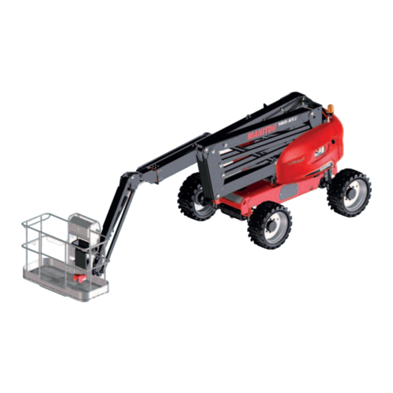
- Page 1 647698 EN (20/07/2018) 160 ATJ RNC 4RD ST5 S1 160 ATJ RC 4RD ST5 S1 180 ATJ RNC 4RD ST5 S1 180 ATJ RC 4RD ST5 S1 OPERATOR'S MANUAL (ORIGINAL INSTRUCTIONS)
- Page 2 - Descriptions and figures are non binding. - MANITOU reserves the right to change its models and their equipment without being required to update this manual. - The MANITOU network, consisting exclusively of qualified professionals, is at your disposal to answer all your questions.
- Page 3 MANITOU BF. Any violation of the aforementioned may lead to civil and criminal prosecution. The logos as well as the visual identity of the company are the property of MANITOU BF and may not be...
- Page 4 1 - OPERATING AND SAFETY INSTRUCTIONS 2 - DESCRIPTION 3 - MAINTENANCE 160 ATJ RNC 4RD ST5 S1 160 ATJ RC 4RD ST5 S1 180 ATJ RNC 4RD ST5 S1 180 ATJ RC 4RD ST5 S1...
- Page 5 1 - OPERATING AND SAFETY INSTRUCTIONS 1 - 1...
- Page 6 1 - OPERATING AND SAFETY INSTRUCTIONS INSTRUCTIONS TO THE COMPANY MANAGER THE SITE THE OPERATOR PLATFORM A – SUITABILITY OF THE PLATFORM FOR THE TASK ........... . 1-4 B - ADAPTING THE PLATFORM TO USUAL ENVIRONMENTAL CONDITIONS .
- Page 7 IF THE PLATFORM IS NOT TO BE USED FOR A LONG TIME 1-14 INTRODUCTION 1-14 PREPARING THE PLATFORM 1-14 PROTECTING THE ENGINE (DIESEL PLATFORM) 1-14 BATTERY CHARGING (ELECTRIC PLATFORM) 1-14 PROTECTING THE PLATFORM 1-14 BRINGING THE PLATFORM BACK INTO SERVICE 1-14 DISPOSING OF THE PLATFORM 1-15...
- Page 8 A – SUITABILITY OF THE PLATFORM FOR THE TASK - MANITOU has ensured that this platform is suitable for use under the standard operating conditions defined in this operator’s manual, with an OVERLOAD test coefficient of 1.25 and an OPERATIONAL test coefficient of 1.1, as stipulated in harmonised standard EN 280 for MPLP (Mobile Personnel Lifting Platforms).
- Page 9 C - MODIFYING THE PLATFORM IMPORTANT It is strictly prohibited to replace platform components with components not approved by Manitou (batteries, wheels, basket, etc.). IMPORTANT It is strictly forbidden to change the structure and settings of the various components of your platform (hydraulic pressure, calibrating limiters, engine speed, sensors, addition of extra equipment, addition of counterweight, unapproved attachments, alarm systems, etc.) yourself.
- Page 10 INSTRUCTIONS FOR THE OPERATOR INTRODUCTION IMPORTANT The risk of accident while using, servicing or repairing your platform can be reduced if you follow the safety instructions and preventive measures detailed in these instructions. Failure to respect the safety and operating instructions, or the instructions for repairing or servicing your platform may lead to serious, even fatal accidents.
- Page 11 - Ensure that the guard rail and/or the access gate (according to model) is fully in the locked position before operating the platform from the basket. - MANITOU recommends a safety harness in the operator’s size be provided when the platform is in use (for the harness attachment in the basket, 2 - DESCRIPTION).
- Page 12 C - ENVIRONMENT - Comply with site safety regulations. - The platform can be operated from the ground: ensure that you forbid access. - If you have to use the platform in a dark area or at night, make sure it is equipped with working lights. - The platforms may not be used as cranes or elevators for the permanent transport of people or materials, nor as jacks or supports.
- Page 13 IMPORTANT Do not use this machine during lightning storms, snow storms, during frosty periods or in hazardous weather conditions. In case of strong wind exceeding 45 km/h, do not make any movement that may endanger the platform’s stability. - To visually recognise this wind speed, refer to the empirical wind evaluation scale below: BEAUFORT scale (wind speed at a height of 10 m on a flat site) Speed Speed...
- Page 14 F - OPERATING THE PLATFORM SAFETY INSTRUCTIONS IMPORTANT Operators should be aware of the risks connected with using the platform, notably: - Risk of losing control. - Risk of losing lateral and frontal stability of the platform. The operator must remain in control of the platform. - Do not carry out operations which exceed the capacities of your platform.
- Page 15 INSTRUCTIONS FOR WELDING AND BLOW TORCH WORK ON AN EXTERNAL STRUCTURE IMPORTANT Ensure that there are no hydraulic or electrolyte leaks on the platform. IMPORTANT When welding, work in the opposite direction from the control console to avoid sparks damaging it. Any welding and cutting (blow torch) work from the basket on a building’s metallic structures requires the following precautions to be taken: A - WITH AN ELECTRICAL WELDING SET...
- Page 16 PLATFORM MAINTENANCE INSTRUCTIONS GENERAL INSTRUCTIONS - Read the operator’s manual carefully. - Wear clothes suitable for the maintenance of the lift truck, avoid wearing jewellery and loose clothes. Tie and protect your hair, if necessary. - DIESEL PLATFORM: • Make sure the area is adequately ventilated before starting up the platform. •...
- Page 17 IMPORTANT Welding operations for the purposes of maintenance or repairs must only be carried out by persons authorised by MANITOU. WASHING THE PLATFORM - Clean the platform or at least the area concerned before any intervention.
- Page 18 IF THE PLATFORM IS NOT TO BE USED FOR A LONG TIME INTRODUCTION The following recommendations are intended to prevent the platform from being damaged when it is withdrawn from service for an extended period. IMPORTANT Procedures to follow if the platform is not to be used for a long time and for starting it up again afterwards must be performed by your dealership. This period of long-term stoppage must not exceed 12 months.
- Page 19 • Glass items can be removed and collected for processing by glaziers. ENVIRONMENTAL PROTECTION By entrusting the maintenance of your platform to the MANITOU network, the risk of pollution is limited and the contribution to environmental protection is made. WORN OR DAMAGED PARTS •...
- Page 20 1 - 16...
- Page 21 2 - DESCRIPTION 2 - 1...
- Page 22 2 - DESCRIPTION "CE" DECLARATION OF CONFORMITY STICKERS IDENTIFICATION OF THE PLATFORM 2-14 CHARACTERISTICS 2-16 160 ATJ... CHARACTERISTICS 2-20 180 ATJ... DIMENSIONS AND DIAGRAM 2-24 160 ATJ... DIMENSIONS AND DIAGRAM 2-26 180 ATJ... SAFETY COMPONENTS 2-28 CONTROL PANEL AND SAFETY DEVICES AT GROUND LEVEL 2-29 CONTROL PANEL AND SAFETY DEVICES IN THE BASKET 2-30...
- Page 23 2 - 3...
- Page 24 The manufacturer declares that the machine manufacturer decla he m : 160 ATJ RNC 4RD ST5 S1 - 160 ATJ RC 4RD ST5 S1 T5 S1 described below 180 ATJ RNC 4RD ST5 S1 - 180 ATJ RC 4RD ST5 S1 T5 S1 - Est conforme aux directives suivantes et à...
- Page 25 2 - 5...
- Page 26 STICKERS IMPORTANT Clean all stickers so that they are legible. Any stickers which are illegible or damaged must be replaced. Check that the stickers are present after replacing any spare parts. 1 - WHITE ARROW ...............Part No. 833553 ....2-8 2 - BLACK ARROW .
- Page 27 22 23 *: Depending on version 26 12 19 20 NOTE: The grey grids indicate that the stickers are hidden under the covers. 2 - 7...
- Page 28 1 - WHITE ARROW Part No. 833553 Indicates forward driving direction, PLATFORM OPERATION: TRANSPORT/WORKING POSITION. 2 - BLACK ARROW Part No. 833554 Indicates reverse driving direction, PLATFORM OPERATION: TRANSPORT/WORKING POSITION. 3 - INSTRUCTIONS LOCATION Part No. 52562839 Indicates location of the instructions for use. 4 - BASKET SAFETY INSTRUCTIONS Part No.
- Page 29 5 - GROUND SAFETY INSTRUCTIONS Part No. 685608 (1) / 52621077 (2) Indicates: : The safety and operating instructions must be read before starting the platform. : The platform must not be towed in the event of breakdown. : It is strictly forbidden to direct a pressure washer nozzle over the control panels and electrical components.
- Page 30 10 - DANGER OF CRUSHING Part No. 679452 (1) / 52621082 (2) Indicates that it is strictly prohibited to stand in this area when the platform is moving. The components on which the stickers are present could crush you. N.B.: (1) = 1st version. (2) = 2nd version. The reference (1) must be replaced by reference (2) for spare parts orders.
- Page 31 15 - BACKUP PUMP Part No. 676992 Indicates the procedure to be followed for using the backup pump, RESCUE PROCEDURE. 16 - EMERGENCY CONTROL PROCEDURE Part No. 831465 Indicates the procedure to be followed for using the emergency controls for proportional distributor , RESCUE PROCEDURE.
- Page 32 21 - SLINGING POINT Part No. 833291 Indicates the location of the platform's slinging points, 3 - MAINTENANCE: OCCASIONAL OPERATION. 22 - SLINGING Part No. 52579620 160 ATJ... 23 - SLINGING Part No. 52589809 180 ATJ... Indicates the main characteristics that are useful when slinging the platform, MAINTENANCE: OCCASIONAL OPERATION.
- Page 33 27 - BATTERY LOCATION Part No. 52509705 Indicates location of battery. 28 - FAULT CODES Part No. 52579619 Indicates the fault codes and location of the electrical components: - Sensors (AS, DS, IS, TS). - Electrovalves (EV). - Solenoid coils (EW). 29 - MAINTENANCE STAND Part No.
- Page 34 "Valve clearance (cold): IN / EX" Valve clearances (cold): IN/EX "Inj. timing" Injection timing "Engine disp. " Engine capacity ECS: EM, IFI "Category" Category HYDROSTATIC PUMP "CNR" MANITOU Part No. "TYP" Codification "MNR" Manufacturing number "SN" Serial number "FD" Date of manufacture 2 - 14...
- Page 35 AUXILIARY PUMP "MNR" Manufacturing number "FD" Date of manufacture "SN" Serial number FRONT AXLE Type Serial number MANITOU part No. REAR AXLE Type Serial number MANITOU part No. 2 - 15...
- Page 36 CHARACTERISTICS 160 ATJ... Diameter of Diameter of wheels: wheels: LOAD SPECIFICATIONS ± 840 mm 908 mm Platform - Maximum capacity of basket kg (lbs) 230 (507) - Maximum wind speed when operating outside km/h - Number of people in the basket in indoor use - Number of people in the basket in outdoor use - Unladen platform weight kg (lbs)
- Page 37 Diameter of Diameter of wheels: wheels: ENGINE ± 840 mm 908 mm Type KUBOTA D1105-E4B Fuel Diesel Number of cylinders Cubic capacity 1123 Idling speed unladen 1300 Maximum speed unladen 3000 Power at 3,000 rpm 18.5 Maximum torque at 2,300 rpm Unladen weight kg (lbs) 93 (205)
- Page 38 Diameter of Diameter of wheels: wheels: HYDRAULIC CIRCUIT ± 840 mm 908 mm Auxiliary hydraulic pump - Type BOSCH REXROTH - Maximum cylinder capacity - Maximum unladen flow rate L/min Distributor - Type DANFOSS - Maximum pressure Filtration - Suction μm - Pressure μm...
- Page 39 Diameter of Diameter of wheels: wheels: SOUND AND VIBRATION ± 840 mm 908 mm Sound power level LwA Vibrations affecting body in the basket - Average quadratic values for the body <0.5 Diameter of Diameter of EQUIPMENT wheels: wheels: ± 840 mm 908 mm Orange rotating beacon light...
- Page 40 CHARACTERISTICS 180 ATJ... LOAD SPECIFICATIONS ± Platform - Maximum capacity of basket kg (lbs) 230 (507) - Maximum wind speed when operating outside km/h - Number of people in the basket in indoor use - Number of people in the basket in outdoor use - Unladen platform weight kg (lbs) 7430 (16380)
- Page 41 ENGINE ± Type KUBOTA D1105-E4B Fuel Diesel Number of cylinders Cubic capacity 1123 Idling speed unladen 1300 Maximum speed unladen 3000 Power at 3,000 rpm 18.5 Maximum torque at 2,300 rpm Unladen weight kg (lbs) 93 (205) 5 (11) Type of cooling Water Puller Emissions...
- Page 42 HYDRAULIC CIRCUIT ± Auxiliary hydraulic pump - Type BOSCH REXROTH - Maximum cylinder capacity - Maximum unladen flow rate L/min Distributor - Type DANFOSS - Maximum pressure Filtration - Suction μm - Pressure μm - Operation μm ELECTRIC CIRCUIT ± Battery - Type EXIDE...
- Page 43 SOUND AND VIBRATION ± Sound power level LwA Vibrations affecting body in the basket - Average quadratic values for the body <0.5 EQUIPMENT ± Orange rotating beacon light Standard Hour meter Standard Proportional diesel level display Standard Fuel/battery low level alarm Standard Tool box in basket Standard...
- Page 44 DIMENSIONS AND DIAGRAM 160 ATJ... Diameter of wheels: Diameter of wheels: 840 mm 908 mm Standard Standard Wide basket Wide basket basket basket 6680 6720 4445 4490 4485 4530 2200 1100 2370 2410 2630 2830 2690 2810 2320 1380 3750 6100 6180 6100 6180...
- Page 45 Diameter of wheels: Diameter of wheels: Diameter of wheels: Diameter of wheels: 840 mm 908 mm 840 mm 908 mm 7510 7550 7366 7406 7795 14015 14055 2905 12475 12515 12334 12374 3890 6980 16 m 15 m 14 m 13 m 12 m 11 m...
- Page 46 DIMENSIONS AND DIAGRAM 180 ATJ... Standard basket Wide basket 7790 5560 2200 1100 2475 2485 2560 2780 2320 1380 3750 4535 4675 7030 7095 2770 ° / % 43.5 / 95 2 - 26...
- Page 47 7555 7420 10010 16180 3545 14640 13350 4530 9190 10 m 11 m 18 m 17 m 16 m 15 m 14 m 13 m 12 m 11 m 10 m 10 m 11 m 2 - 27...
- Page 48 SAFETY COMPONENTS GUARDRAIL IMPORTANT Do not attach the guardrail with a clamp, twine or any device that could prevent it from functioning properly. - Raise the guardrail and keep it raised to get in and out of the basket. HARNESS ATTACHMENT POINTS IMPORTANT Only one operator is permitted to use each attachment point.
-
Page 49: Table Of Contents
CONTROL PANEL AND SAFETY DEVICES AT GROUND LEVEL IMPORTANT These platforms are equipped with an integrated tilting sensor in the ground control panel 1 - INSTRUCTIONS AND SAFETY INSTRUCTIONS: PLATFORM MAINTENANCE INSTRUCTIONS). The left and right are defined in OPERATING THE PLATFORM: TRANSPORT/WORKING POSITION. 1 - EMERGENCY STOP BUTTON. - Page 50 CONTROL PANEL AND SAFETY DEVICES IN THE BASKET IMPORTANT Drive forwards, drive backwards, the left and right are defined in OPERATING THE PLATFORM: TRANSPORT/WORKING POSITION. Up to machine no. 01005238 From machine no. 01005239 2 - 30...
- Page 51 13 - PEDAL SWITCH ......................2-35 14 - EMERGENCY STOP BUTTON.
-
Page 52: Emergency Stop Button
1 - EMERGENCY STOP BUTTON IMPORTANT In all cases this control takes priority, even if the movements are executed from the basket control panel. Movements may stop suddenly if the emergency stop is activated. 2 positions: - OFF (locked): Press the button to cut off movement and to stop the engine. - ON (unlocked): Pull the button or turn it a quarter turn to the right and release it. -
Page 53: Control Selection Switch On The Ground/ In The Basket
5 - CONTROL SELECTION SWITCH ON THE GROUND/ IN THE BASKET 2 positions: CONTROLS IN THE BASKET when the switch is released: • The controls in the basket are activated. GROUND LEVEL CONTROLS: • Push and hold the switch to the right to activate the ground level controls. NOTE: This operating mode is called the "dead man"... -
Page 54: Interface Screen
8 - INTERFACE SCREEN The interface screen displays all the start-up steps and the settings, and gives access to specific sub-menus, such as: • Platform maintenance. • Fault log. • Hour meters (engine operation hours counter, daily usage hour counter, etc.). NOTE: SCREEN DISPLAY - DESCRIPTION OF PAGES. -
Page 55: Orange Rotating Beacon Light
11 - ORANGE ROTATING BEACON LIGHT PERMANENT ORANGE ROTATING BEACON LIGHT option deactivated: The orange rotating beacon light is lit when the controls are activated and when driving/steering the platform, SUB-MENU DEFINITIONS: USER OPTIONS: PERMANENT ORANGE ROTATING BEACON LIGHT. PERMANENT ORANGE ROTATING BEACON LIGHT activated: The orange rotating beacon light is lit when the platform is powered up, SUB-MENU DEFINITIONS: USER OPTIONS: PERMANENT ORANGE ROTATING BEACON LIGHT. -
Page 56: Engine Starter Button
16 - ENGINE STARTER BUTTON IMPORTANT Do not keep the button pressed for more than 15 seconds. - Press and hold down the button to start the engine. - Release button once the engine has started. 17 - HORN BUTTON - Press and hold down the button to sound the horn. -
Page 57: Main Jib And Turntable Control Handle
21 - MAIN JIB AND TURNTABLE CONTROL HANDLE - Press and hold down the foot switch. RAISE THE MAIN JIB - Push and hold the control handle forward. Release to stop. LOWER THE MAIN JIB - Pull and hold the control handle back. Release to stop. TURN THE TURNTABLE TO THE LEFT - Push and hold the control handle to the left. -
Page 58: Driving Speed Selection Switch
24 - DRIVING SPEED SELECTION SWITCH IMPORTANT Always brake the platform before selecting the driving speed. 3 positions: TORTOISE speed for driving the platform at slow speed. RAMP speed for driving the platform at slow speed with full power. HARE speed for driving the platform at high speed. NOTE: Driving speed selection only works in the transport position, OPERATING THE PLATFORM: TRANSPORT/WORKING POSITION. -
Page 59: Differential Locking Button
27 - DIFFERENTIAL LOCKING BUTTON IMPORTANT It is recommended that differential locking is only used when the wheels are correctly aligned with the axis of the machine. - Press and hold down the button to activate the differential locking when the platform is being driven. -
Page 60: Use On Slope Button
29 - USE ON SLOPE BUTTON IMPORTANT The platform could tip over when this function is used. Use with extreme caution. - Press the button and hold it down to action the locked controls (except driving forward and backwards) when the tilt alarm is activated. TILT/OSCILLATION ALARM INDICATOR LIGHT. -
Page 61: Low Fuel Level Alarm Light
MAJOR FAULTS AUDIBLE ALARM All controls are locked. Refer to CAN communication fault STOP the maintenance personnel. Low engine oil pressure Stop the machine immediately and refer to the maintenance personnel. Sounds intermittently High coolant temperature NOTE: The engine stops after 90 seconds. -
Page 62: Battery Alarm Indicator Light
33 - BATTERY ALARM INDICATOR LIGHT From machine no. 01005239 The indicator light comes on and the audible alarm sounds intermittently when the engine is automatically stopped by the ENGINE AUTOMATIC STOP SYSTEM "STOP AND GO" and the battery voltage is low: It is recommended to restart the engine when the light is on. -
Page 63: Pressure Sensitive Bar (Option: "Safemansystem")
38 - PRESSURE SENSITIVE BAR (OPTION: "SAFEMANSYSTEM") OPTIONS. 39 - AUDIBLE ALARM The audible alarm sounds: - Once after the platform has been powered up. - Intermittently when the platform is on a steep slope or if a blocking fault in the oscillating axle is detected, TILTING/OSCILLATION ALARM INDICATOR LIGHT. - Page 64 SCREEN DISPLAY - DESCRIPTION OF PAGES START-UP PAGE Once the platform is powered up, the start-up page is displayed briefly, then the PREHEAT PAGE is displayed. NOTE: The current time is displayed at the top of each page. The platform serial number is displayed at the bottom of each page.
- Page 65 EDITING A SUB-MENU - After selecting a menu, select the required sub-menu (if necessary) using the ARROW keys - Press the MINUS/PLUS keys to change the settings. - Confirm once by pressing the key OK . A confirmation message is displayed.
- Page 66 FAULT PAGE IMPORTANT Certain controls may be locked depending on the fault. Refer to the maintenance personnel if there is a fault. A FAULT PAGE is displayed when a fault is detected. - Press the FAULT key to display the FAULT CODE/ALARM PAGE. ALARM PAGE An ALARM PAGE is displayed intermittently with the FAULT PAGE or the WORK PAGE when an alarm is triggered.
- Page 67 FAULT/ALARM CODE PAGE The fault/alarm code and its description are displayed on this page. - Press the key OK so that the fault or alarm is no longer displayed. This action is recorded in the faults/alarm history. NOTE: The illustration shows an example of a fault code. 2 - 47...
- Page 68 DEFINITION OF SUB-MENUS Dealers/Rental User companies Access code not required Access code required Icons Menus/sub-menus Adjustment Adjustment Display Display parameters parameters "Code" Code "Klaxon mode" Horn mode (1) "Always flash. light" Permanent rotating beacon light (2) Stop & go (3) "Locking telescop"...
- Page 69 Dealers/Rental User companies Access code not required Access code required Icons Menus/sub-menus Adjustment Adjustment Display Display parameters parameters "Oil change at" Oil change in "Oil filter at" Oil filter in "Air filter at" Air filter in "Fuel filter at" Diesel filter in "Maintenance"...
- Page 70 Dealers/Rental User companies Access code not required Access code required Icons Menus/sub-menus Adjustment Adjustment Display Display parameters parameters "Contrast" Contrast "Brightness" Light level "Screen settings" Screen adjustments "Date and time" Date and time "Button tones" Key beeps "Codification" Codification "Machine selection" Machine selection "Rental"...
- Page 71 USING THE PLATFORM IMPORTANT Part 1 - INSTRUCTIONS AND SAFETY INSTRUCTIONS must be read and understood before operating the platform. TRANSPORT/WORKING POSITION TRANSPORT POSITION The platform in the transport position when: - The main jib is completely lowered. - The secondary jib is completely lowered. - The telescope is completely retracted.
- Page 72 OPERATION FROM THE GROUND LEVEL CONTROL PANEL IMPORTANT CONTROL PANEL AND SAFETY DEVICES ON THE GROUND for detailed information about the ground controls. SWITCH THE PLATFORM ON - Ensure that the emergency stop buttons on the ground level and basket control panels are in the ON position. - BATTERY CUT-OFF option: Turn the battery cut-off to the ON position.
- Page 73 OPERATION FROM THE BASKET CONTROL PANEL IMPORTANT CONTROL PANEL AND SAFETY DEVICES IN THE BASKET for detailed information about the controls in the basket. TURN THE PLATFORM ON/OFF OPERATION FROM THE GROUND CONTROL PANEL. START THE ENGINE - Switch on the access platform. - Wait for the preheat cycle to finish, PREHEAT INDICATOR LIGHT.
- Page 74 ENGINE AUTOMATIC STOP SYSTEM "STOP AND GO" UP TO MACHINE No. 01005238 IMPORTANT Do not open the engine cover (left turntable cover) if the ENGINE AUTOMATIC STOP SYSTEM "STOP AND GO" is activated. Always deactivate the ENGINE AUTOMATIC STOP SYSTEM "STOP AND GO" before opening the engine cover (left turntable cover).
- Page 75 FROM MACHINE No. 01005239 DEACTIVATE OR ACTIVATE THE ENGINE AUTOMATIC STOP SYSTEM "STOP AND GO" NOTE: The platform must be turned on. The engine may or may not be started. NOTE: A pictogram indicates the system status, SCREEN DISPLAY: DESCRIPTION OF PAGES: WORK PAGE.
- Page 76 CONTROLS LOCKED Some controls are locked (refer to the tables below): - When the basket load has reached maximum capacity (OVERLOAD ALARM). - When the platform is on a steep slope or if a blocking fault in the oscillating axle is detected, (TILTING/OSCILLATION ALARM). TRANSPORT POSITION GROUND CONTROLS OVERLOAD ALARM...
- Page 77 2 - 57...
- Page 78 TRANSPORTING THE PLATFORM IMPORTANT Check that the safety instructions associated with the flatbed have been correctly applied before loading the platform and ensure that the driver of the vehicle has been informed of the dimensional characteristics and total weight of the platform. Ensure that the flatbed has adequate dimensions and load capacity for transporting the platform, CHARACTERISTICS and STICKERS.
- Page 79 CONFIGURE THE PLATFORM FOR TRANSPORT The platform may be transported in A - TRANSPORT POSITION or B - FOLDED POSITION. A - TRANSPORT POSITION B - FOLDED POSITION A - TRANSPORT POSITION: OPERATING THE PLATFORM: TRANSPORT/WORKING POSITION: • Place the platform in the transport position. •...
- Page 80 ANCHORING THE ACCESS PLATFORM IMPORTANT The platform is equipped with 8 lashing points ( STICKERS: LASHING POINT); comply with the country's regulations concerning the minimum number of lashing points required when transporting a platform. - Fix chocks to the flatbed truck at the front and rear of each of the platform’s wheels. - Fix chocks to the flatbed on the inner side of each of the platform's wheels.
- Page 81 1900 kg (4190 lbs) 2150 kg (4740 lbs) 3800 kg (8380 lbs) 3850 kg (8490 lbs) 7550 kg (16645 lbs) 2 - 61...
- Page 82 RESCUE PROCEDURE IMPORTANT This procedure should be read and fully understood by the operator and any other persons likely to be involved with working on the platform in the event of a breakdown or a person getting trapped in the basket. SHOULD THE USER FEEL ILL - PRIORITY CONTROLS If the operator in the basket should fall ill or find himself incapable of manoeuvring, the person present on the ground can take over the platform controls from the ground...
- Page 83 IF THERE IS AN ACCIDENT OR BREAKDOWN - EMERGENCY CONTROLS IMPORTANT The tilt alarm and overload alarm may no longer be active while the emergency controls are in use. The backup pump should be activated for a maximum of 4 minutes, then wait 10 minutes before reactivating the pump for a new 4 minute cycle.
- Page 84 RAISE THE SECONDARY JIB 1 - Place the lever on the manual control 2 - Press the backup pump button and hold it down. 3 - Push the lever to the right to raise the secondary jib, stop when the desired position is reached.
- Page 85 RAISE THE JIB 1 - Place the lever on the manual control 2 - Screw the thumbwheel until it stops. 3 - Press the backup pump button and hold it down. 4 - Push the lever to the right to raise the jib, stop when the desired position is reached.
- Page 86 OPTIONS 1 - GENERATOR IMPORTANT Do not connect the cord extensions, power supply bars or plugs with multiple sockets to the electric power socket in the basket. Overvoltages could occur when the generator is started. The engine must be started to activate the generator. - Press generator button and release it to start the generator.
- Page 87 3 - SECONDARY PROTECTION SYSTEM "SAFEMANSYSTEM" IMPORTANT Operate the controls extremely carefully during attempts at clearance. If the audible alarm sounds intermittently and rapidly and the blue flashing light flashes rapidly: The platform can be used, but the secondary protection system "SafeManSystem" is deactivated; consult the maintenance personnel. NOTE: The audible alarm sounds once and the blue flashing light flashes several times when the platform is powered up.
- Page 88 2 - 68...
- Page 89 3 - MAINTENANCE 3 - 1...
- Page 90 3 - MAINTENANCE INTRODUCTION ORIGINAL MANITOU SPARE PARTS AND EQUIPMENT PLATFORM MAINTENANCE DAILY AND MONTHLY MAINTENANCE COMPULSORY SERVICE AFTER FIRST 500 HOURS OR 6 MONTHS PERIODIC MAINTENANCE OCCASIONAL MAINTENANCE AND OPERATION FILTERS CARTRIDGES AND BELTS LUBRICANTS AND FUEL 3-10 10 H - DAILY SERVICE OR EVERY 10 HOURS OF SERVICE...
- Page 91 • Efficient help with diagnosis. • Improvements due to experience feedback. • Operator training. • Only the MANITOU network has detailed knowledge of the design of the access platform and therefore the best technical ability to provide maintenance. IMPORTANT ORIGINAL REPLACEMENT PARTS ARE DISTRIBUTED EXCLUSIVELY BY MANITOU AND ITS DEALER NETWORK.
- Page 92 OCCASIONAL MAINTENANCE AND OPERATION IMPORTANT OCCASIONAL MAINTENANCE AND OPERATIONS MUST BE PERFORMED BY MAINTENANCE PERSONNEL OR AN APPROVED PROFESSIONAL FROM THE MANITOU NETWORK. These maintenance operations are to be carried out when needed for the safety and upkeep of the platform.
- Page 93 COMPULSORY SERVICE AFTER FIRST 500 HOURS OR 6 MONTHS FIRST 500 HOURS BEFORE THE FIRST 6 MONTHS - If the platform has reached the first 500 hours of service before the first 6 months have expired, perform both the compulsory service and periodic 500-hour service ( 500 H - PERIODIC MAINTENANCE - EVERY 500 HOURS OF SERVICE OR 1 YEAR).
- Page 94 PERIODIC MAINTENANCE MAINTENANCE SCHEDULE 250 H 500 H 750 H WHEN DUE FIRST 500 HOURS FIRST 6 MONTHS OR 6 MONTHS OR 1 YEAR MANDATORY SERVICE PERIODIC MAINTENANCE MANDATORY SERVICE MACHINE COUNTER DATE OF SERVICING 1,000 H 1,500 H 2,000 H 1,250 H 1,750 H WHEN DUE...
- Page 95 250 H - PERIODIC MAINTENANCE - EVERY 250 HOURS OF SERVICE OR 6 MONTHS ALSO PERFORM THE DAILY MAINTENANCE. - CHECK Injection pipes, fuel hoses and the hose clamps ............3-26 - CHECK Reduction gearbox impermeability .
- Page 96 1,000 H - PERIODIC SERVICE - EVERY 1,000 HOURS OF SERVICE OR 2 YEARS ALSO PERFORM THE DAILY SERVICE AND THE PERIODIC SERVICES AT 250 HOURS AND 500 HOURS OF SERVICE. - CLEAN Fuel tank ................... 3-44 - REPLACE Dry air filter safety cartridge .
- Page 97 FILTERS CARTRIDGES AND BELTS 500 H - PERIODIC SERVICE - EVERY 500 HOURS OF SERVICE OR 1 YEAR ENGINE OIL FILTER DRY AIR FILTER CARTRIDGE Part number: 894022 Part number: 942077 ALTERNATOR/FAN BELT FUEL FILTER CARTRIDGE Part number: 959614 Part number: 781909 FUEL PRE-FILTER PRESSURE HYDRAULIC FILTER CARTRIDGE Part number: 734146...
- Page 98 USE THE RECOMMENDED LUBRICANTS AND FUEL: - For topping up, oils may not be miscible. - For oil changes, MANITOU oils are perfectly appropriate. DIAGNOSTIC ANALYSIS OF OILS If a service or maintenance contract has been set up with the dealer, a diagnostic analysis of engine, transmission and axle oils may be requested depending on the rate of use.
- Page 99 5 LITRES 20 LITRES 55 LITRES 209 LITRES - MANITOU OIL 15W40 API CH4 661706 582357 582358 582359 - MANITOU ISO VG 46 HYDRAULIC OIL 545500 582297 546108 546109 - SPECIAL MANITOU OIL FOR IMMERSED BRAKES 545976 582391 894257 - MANITOU SAE80W90 MECHANICAL TRANSMISSION OIL...
-
Page 100: Check General Inspection
10 H - DAILY SERVICE OR EVERY 10 HOURS OF SERVICE CHECK General inspection IMPORTANT Consult the maintenance personnel if there is doubt about the condition of the platform. NOTE: The turntable covers must be open and the battery cover must be removed to carry out the general inspection of the platform. -
Page 101: Check Engine Oil Level
CHECK Engine oil level - Open the left-hand turntable cover. - Remove the dipstick . Clean it with a clean cloth and put it back in place. - Remove the dipstick. The level is correct when the engine oil is between the 2 marks - If the level is low: •... -
Page 102: Check Alternator/Fan Belt
CHECK Alternator/fan belt IMPORTANT If there is doubt about the condition of the belt, refer to the maintenance personnel. NOTE: The left turntable cover is open. - Check the condition of the belt . Ensure there are no cracks or signs of wear. - Check the belt tension between the crankshaft pulley and the alternator pulley. -
Page 103: Check Platform Controls
CHECK Platform controls IMPORTANT 2 - DESCRIPTION for more information on the control panels on the ground and in the basket. Select a test area on a firm, level surface that is free of any obstacles. Look around and above you when manoeuvring the platform (lifting, rotation, etc.). Pay particular attention to electric lines and any object that may be within the platform’s field of operation. - Page 104 CONTROLS: ROTATION OF TURNTABLE, MAIN JIB, SECONDARY JIB, TELESCOPE, JIB, BASKET/JIB TILT AND BASKET ROTATION NOTE: The engine has been started. GROUND LEVEL CONTROL PANEL: - Do not touch the selector switch on the controls at ground level/in the basket. Test the controls one by one. Result: •...
- Page 105 UPPER JIB, SECONDARY JIB AND TELESCOPE POSITION SENSORS NOTE: The engine has been started. CONTROL PANEL IN THE BASKET: - Select TORTOISE speed. - Drive the platform forward for a short distance. Assess and remember the speed of the platform. - Raise the main jib for 3 seconds.
- Page 106 SLOPE ALARM NOTE: The engine has been started. TORTOISE speed is selected. GROUND LEVEL CONTROL PANEL: - Enter the menu "SLOPE MANAGEMENT" SLOPE MANAGEMENT - Press the key OK to start the tilt sensor test "SELF-TEST" SELF-TEST. NOTE: The texts in brackets are displayed when the language "English" (English) is selected. - Wait for the SELF-TEST to finish: •...
-
Page 107: Check Secondary Protection System "Safemansystem" (Option)
CHECK Secondary protection system "SafeManSystem" (OPTION) IMPORTANT Select a test area on a firm, level surface that is free of any obstacles. Shut the platform down if a malfunction is detected. - Switch on the access platform. Result: • The audible alarm should sound once. •... -
Page 108: Monthly Maintenance Or Every 50 Hours Of Service
Never smoke or approach with a flame during this check. If there is doubt about the condition of the injection pipes, fuel hoses and hose clamps, have them replaced by an authorised professional from the Manitou network. - Put the maintenance stand in place, OCCASIONAL OPERATION. -
Page 109: Check Impermeability Of The Front And Rear Gear Reducers
CHECK Impermeability of the front and rear gear reducers NOTE: Check the gear reducers one by one. - Check no oil is leaking from the gear reducers and plugs. - If a leak is detected: • Turn the wheel to put the drain/filler plug in the horizontal position. -
Page 110: Check Direction Of Travel "Drive Enable" (Option)
Clean the radiators more often when the platform is operating in a dusty environment. If there is doubt about the condition of the hoses and hose clamps for the coolant radiator, it is essential to have them replaced by an authorised professional from the Manitou network. - Open the left-hand turntable cover. -
Page 111: Clean
Never use the platform without a dry air filter safety cartridge or if it is damaged. If there is doubt about its condition, have it replaced by an approved professional from the Manitou network. If there is doubt about the condition of the air intake line, the air suction outlet hose and hose clamps, have them replaced by an authorised professional from the Manitou network. -
Page 112: Lubricate
LUBRICATE Front and rear axles IMPORTANT Lubricate the axles more often when the platform is operating in a dusty environment. - Remove the caps from the lubrication connectors on the steering pivots of the front and rear axles, on the right and left-hand sides. - Inject the lubricant into the lubrication connectors, LUBRICANTS AND FUEL. - Page 113 3 - 25...
- Page 114 250 H - PERIODIC MAINTENANCE - EVERY 250 HOURS OF SERVICE OR 6 MONTHS ALSO PERFORM THE DAILY MAINTENANCE. CHECK Injection pipes, fuel hoses and the hose clamps MONTHLY MAINTENANCE OR EVERY 50 HOURS OF SERVICE. CHECK Reduction gearbox impermeability MONTHLY MAINTENANCE OR EVERY 50 HOURS OF SERVICE.
- Page 115 CHECK Tightening of the fixing screws for the axles IMPORTANT The tightening of the screws should be checked at the latest after the first 50 hours of service, then every 250 hours of service. Not observing this instruction may cause failure of the fixing screws and damage to the axles. WITHOUT OSCILLATING FRONT AXLE OPTION: - Check all the fixing screw tightening torques: •...
- Page 116 CHECK Locking of the front axle oscillating cylinders (OPTION) - Place a sufficiently solid ramp in front of the right front wheel: • A = 7.5 cm minimum, 9 cm maximum. • B = 60 cm maximum. • C = 75 cm minimum, 100 cm maximum. • D = 10° minimum, 25° maximum. - Switch on the platform.
- Page 117 CHECK Overload alarm IMPORTANT Refer to the platform repair manual if the overload alarm is not correctly calibrated. NOTE: The platform is in the transport position. The turntable and the basket should be in the neutral position. The jib is completely lowered.
- Page 118 CHECK Turntable rotation motor oil level - Put the maintenance stand in place, OCCASIONAL OPERATION. - Remove the battery cover - Check no oil is leaking from the turntable rotation motor - Remove the filler plug - Clean the gauge on the filler cap with a clean cloth and put it back in place. - Remove the filler cap.
- Page 119 CLEAN Fuel filter cartridge IMPORTANT Never smoke or approach with a flame when the fuel filter cartridge is being cleaned. Never use the platform without the fuel filter cartridge or if it is damaged. If there is doubt about its condition, 500 H: REPLACE: Fuel filter cartridge.
- Page 120 LUBRICATE Shafts, hubs and cylinder rings - Remove the caps of the lubrication connectors. - Inject the lubricant into each lubrication connector, LUBRICANTS AND FUEL. - Refit the caps of the lubrication connectors. SHAFT CYLINDER RING 3 - 32...
- Page 121 LUBRICATE Telescope IMPORTANT Lubricate the telescope more often when the platform is operating in a dusty environment. - Switch on the platform. Start the engine. - Raise the jib slightly. - Fully extend the telescope. - Check the sliding surfaces of the pads: •...
- Page 122 500 H - PERIODIC SERVICE - EVERY 500 HOURS OF SERVICE OR 1 YEAR ALSO PERFORM THE DAILY SERVICE AND THE PERIODIC SERVICE AT 250 HOURS OF SERVICE. CHECK Tilt sensor IMPORTANT It is essential that the platform is in the transport position with the turntable and the basket in the neutral position, the jib must be fully lowered. Refer to the platform repair manual if the tilt sensor is not correctly calibrated.
- Page 123 CHECK Telescope setting IMPORTANT Not adhering to this instruction could damage the telescope. It is recommended that the telescope wedging is adjusted if the clearances are higher than the maximum values, REPAIR MANUAL. - Check all the wheel nut tightening torques •...
- Page 124 CHECK Tightening of the fixing screws for the crown gear IMPORTANT The tightening of the screws should be checked at the latest after the first 50 hours of service, then every 500 hours of service. Not observing this instruction may cause failure of the fixing screws and damage to the crown gear. - Put the maintenance stand in place, OCCASIONAL OPERATION.
- Page 125 CHECK Hydraulic hoses IMPORTANT Always use a piece of paper or cardboard to check there are no hydraulic oil leaks. Replace any damaged hydraulic hoses. NOTE: The maintenance stand is put in place. The battery cover and the engine grille are taken off. The left turntable cover is open.
- Page 126 REPLACE Fuel filter cartridge IMPORTANT Never smoke or approach with a flame when the fuel filter cartridge is being replaced. Never use the platform without the fuel filter cartridge or if it is damaged. NOTE: The maintenance stand is put in place. The battery cover and the engine grille are taken off.
- Page 127 REPLACE Engine oil REPLACE Engine oil filter IMPORTANT The replacement of the engine oil and the engine oil filter should be performed at the latest after the first 50 hours of service, then every 500 hours of service. NOTE: The maintenance stand is put in place. The battery cover and the engine grille are taken off.
- Page 128 REPLACE Dry air filter cartridge IMPORTANT Never use the platform with a damaged air filter unit. Never use the platform without the dry air filter cartridge or if it is damaged. Never use the platform without the dry air filter safety cartridge or if it is damaged. If there is doubt about its condition, 1,000 H: REPLACE:Dry air filter safety cartridge.
- Page 129 REPLACE Turntable rotation motor oil IMPORTANT It is recommended that the oil is slightly warm before being changed. NOTE: The maintenance stand is put in place. The battery cover and the engine grille are taken off. The left turntable cover is open. CHANGE THE OIL - Place a drain tank under the drain plug - Remove the drain plug and the filler plug...
- Page 130 REPLACE Hydrostatic transmission filter cartridge IMPORTANT Never use the platform without the hydrostatic transmission filter cartridge or if it is damaged. NOTE: The left turntable cover is open. - Clean the outside of the hydrostatic transmission filter with a clean cloth. - Place a drain tank underneath.
- Page 131 3 - 43...
- Page 132 1,000 H - PERIODIC SERVICE - EVERY 1,000 HOURS OF SERVICE OR 2 YEARS ALSO PERFORM THE DAILY SERVICE AND THE PERIODIC SERVICES AT 250 HOURS AND 500 HOURS OF SERVICE. CLEAN Fuel tank IMPORTANT Never smoke or approach with a flame when the fuel tank is being cleaned. - Switch on the platform.
- Page 133 REPLACE Coolant IMPORTANT Wait until the engine cools if it has been running for a while. Do not remove the radiator cap until the engine is completely cooled. NOTE: The left turntable cover is open. DRAIN THE COOLANT - Locate the drain plug under the coolant radiator and put a drain container underneath.
- Page 134 REPLACE Front and rear axle differential oil IMPORTANT It is recommended that the oil is slightly warm before being changed. NOTE: Check the oil in the axle differentials one by one. CHANGE THE OIL - Clean the outside of the axle differential with a clean cloth. - Place a drain tank under the drain plug - Remove the drain plug and the filler plug - Wait until the axle differential is completely drained.
- Page 135 REPLACE Hydraulic oil CLEAN Filling filter and suction strainer IMPORTANT It is recommended that the oil is slightly warm before being changed. Clean the oil can before adding oil to the hydraulic oil tank. Use a clean funnel to add oil to the hydraulic oil tank. CHANGE THE OIL - Put the maintenance stand in place, OCCASIONAL OPERATION.
- Page 136 CHECK Engine silent blocks * CHECK Engine speeds * CHECK Valve lash * CHECK Injection pump * CHECK Injectors * CHECK Hydrostatic transmission circuit pressure * CHECK Speeds of hydraulic movements * CHECK Condition of cylinders * CHECK Condition of electric wiring * RESET Maintenance warning 50 H - MONTHLY MAINTENANCE OR EVERY 50 HOURS OF SERVICE.
- Page 137 2,000 H - PERIODIC SERVICE - EVERY 2,000 HOURS OF SERVICE OR 4 YEARS ALSO PERFORM THE DAILY SERVICE AND THE PERIODIC SERVICES AT 250 HOURS, 500 HOURS AND 1,000 HOURS OF SERVICE. CHECK Coolant and oil radiators * CHECK Water pump and thermostat * CHECK Alternator and starter *...
- Page 138 - 160 ATJ... = 120 kg (wheel diameter: 840 mm), 195 kg (wheel diameter: 908 mm). - 180 ATJ... = 195 kg. NOTE: We recommend the use of the hydraulic jack (MANITOU Part No. 505507) and the safety jack stand (MANITOU Part No. 554772). - Loosen the wheel nuts slightly.
- Page 139 BLEED The fuel supply circuit IMPORTANT Never smoke or approach with a flame when the fuel supply circuit is being bled. Always bleed the fuel supply circuit when: - The fuel tank has been drained and then filled. - There has been a fuel breakdown and then the fuel tank has been filled. - A component of the fuel supply circuit has been cleaned or replaced.
- Page 140 REPLACE Fuses/relays MAIN FUSE BOX - Open the left-hand turntable cover. - Locate the main fuse box - Remove the cover of the box. - Replace the appropriate fuse. General power supply 350 A fuse Backup pump 250 A fuse - Put the box cover.back in place. - Close the left-hand turntable cover.
- Page 141 GROUND CONTROL PANEL FUSES/RELAYS - Open the right-hand turntable cover. - Unlock and open the ground control panel - Replace the appropriate fuse/relay: Engine starter button 5 A fuse Interface screen and interface screen keypad 5 A fuse Interface screen and basket control panel 5 A fuse Working light power supply (OPTION) 5 A fuse...
- Page 142 OCCASIONAL OPERATION Maintenance stand IMPORTANT Always put the maintenance stand in place when you need to carry out a maintenance operation under the raised secondary jib. If you consider there is not enough space to work with the maintenance stand in place: - Raise the secondary jib.
- Page 143 • Change the 4 seals • Lubricate the screws with MANITOU BLACK MULTI-PURPOSE LUBRICANT LUBRICANTS AND FUEL) and put them back in place. • Adjust the distance between the body of the axles and the screw heads = 34 mm ±0.5 mm.
- Page 144 SLING Platform NOTE: The platform is in the transport position. The turntable and the basket should be in the neutral position. The jib is completely lowered. - Switch on the platform. Start the engine. - Turn the turntable to the left as indicated on the illustration below. - Stop the engine.
- Page 145 2330 kg (5140 lbs) 2860 kg (6305 lbs) CG = "CENTER OF GRAVITY" CENTRE OF GRAVITY 1040 mm 1180 mm 40 mm 1160 mm "TOTAL MASS" TOTAL WEIGHT 7550 kg (16645 lbs) 3 - 57...
- Page 146 TRANSPORT Platform 2 - DESCRIPTION: TRANSPORT OF THE PLATFORM. 3 - 58...
Need help?
Do you have a question about the 160 ATJ RNC 4RD ST5 S1 and is the answer not in the manual?
Questions and answers