Table of Contents
Advertisement
Quick Links
Advertisement
Table of Contents

Subscribe to Our Youtube Channel
Related Manuals for Each Energy PHS3K-M1A


Summary of Contents for Each Energy PHS3K-M1A
- Page 1 User Manual Each Energy Technology (Suzhou) Co., Ltd. www.eachenergy.com...
- Page 2 Each Energy Technology (Suzhou) Co., Ltd. Address: Building 4, Modern Industrial Park, Wuzhong Technology City, Suzhou City, Jiangsu P.R.China Tel: +8651266581088 Email: service@eachenergy.com Web: www.eachenergy.com Copyright © Each Energy Technology (Suzhou) Co., Ltd.
- Page 3 Copyright © Each Energy Technology (Suzhou) Co., Ltd. Without written permission, any information of this document (partly or entirely) cannot be extracted, copied or transmitted in any form or by any means. All right reserved. Notice: The information in this document is subject to change without notice.
-
Page 4: Table Of Contents
Contents 1. About the Manual .......................3 2. Product Overview ....................... 4 2.1 Product Description ..................4 2.2 Scope of Delivery ....................7 3. Safety .......................... 7 4. Mounting ........................9 5. Electrical Connection ....................11 5.1 DC Side Connection of Inverters ..............11 5.2 Battery Side Connection of Inverters ............. -
Page 5: About The Manual
Please read this manual carefully before conducting any kind of work on the inverters. Valid Region This manual applies to the operation of Each Energy inverters in Australia, New Zealand, the UK, EU, South America, North America, and Southeast Asia. -
Page 6: Product Overview
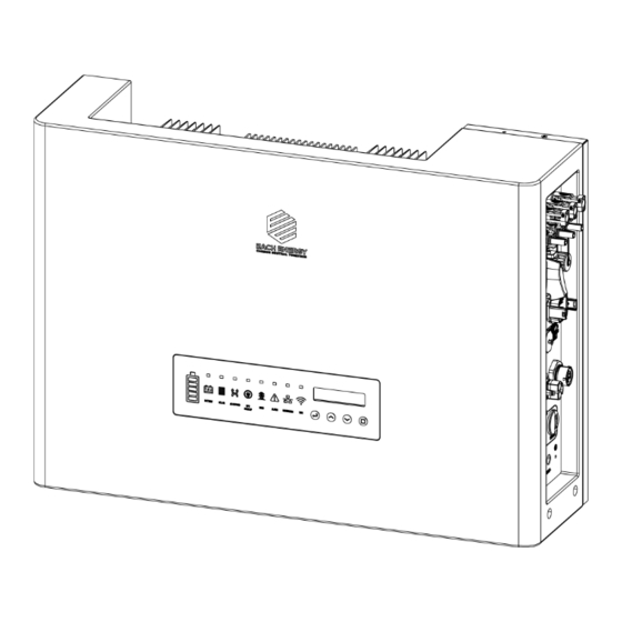
2. Product Overview 2.1 Product Description Each Energy PHS3K-M1A, PHS3.6K-M1A, PHS4K-M1A, PHS4.6K-M1A, PHS5K-M1A, PHS6K-M1A, and PHS8K-M1A single phase hybrid inverters convert DC power generated by photovoltaic panel arrays into AC power, supply power to household load, store power into a battery and feed extra power into utility grid. - Page 7 Operation Panel: name Status Explanation Battery Indicate the battery’s state of charge...
- Page 8 Indicator Flash The battery is being charged Battery A battery has been connected No battery is connected Solar Solar panels have been connected No solar panel is connected AC bypass The backup load is powered by the Grid The backup load is powered by PV or battery Backup Backup power is available...
-
Page 9: Scope Of Delivery
2.2 Scope of Delivery 3. Safety 3.1 Safety Symbols Symbol Explanation Indicates a high level of risk which, if not avoid, DANGER may result in death or serious injury Indicates a medium level of risk which, if not WARNING avoid, may result in death or serious injury... - Page 10 Indicates a low level of risk which, if not avoid, CAUTION may result in minor or moderate injury Indicates a situation which, if not avoided, may NOTE result in device damage or property damage Indicates a danger of electric shock or high voltage ELECTRIC SHOCK Indicates hot surface, do not touch...
-
Page 11: Mounting
Do not touch non-insulated parts or cables, disconnect the machines from voltage sources and guarantee no possible re-connection before working on the machine. Use measuring devices with a DC input voltage range of 600 V or higher only. ... - Page 12 times of the weight of the inverters. The location shall be convenient for electrical connection, operation and maintenance. The ingress protection of the inverter is IP66, so it can be installed both indoors and outdoors. The temperature of the cooling fin may exceed 75 ℃, so select safe locations.
-
Page 13: Electrical Connection
NOTE: To protect your hands from scratch, please wear gloves! 5. Electrical Connection 5.1 DC Side Connection of Inverters This inverters are compatible with monocrystalline silicon, polycrystalline silicon, and thin-film PV panels. NOTE: The inverter cannot be used with functionally earthed PV Arrays. - Page 14 Assemble DC cables to DC connectors: 1) Strip the insulation layer off the DC Cable for a little length. 2) Insert the wire into the Crimp Contact and crimp them with an electrical crimp-er. 3) Thread the cable through the Cable Gland, insert it into the insulator, and gently pull backward the cable to ensure firm connection.
-
Page 15: Battery Side Connection Of Inverters
WARNING:Do not turn off DC switch directly for accident reverse connection of DC inputs or any fault of inverters as it may damage inverters. In that case, turn off the DC switch only when the DC current is below 0.5 A. 5.2 Battery Side Connection of Inverters Please assemble battery cable to battery connectors in the same way as that of PV side connection as described in 5.1. -
Page 16: External Grounding Connection
AC Connector Procedures: 1) Strip the insulation layer off the AC cable about 8 to 15 mm. 2) Thread the AC cable through the Nut and the Housing. 3) Connect wires to the Terminal Block: insert yellow green wire to the grounding (PE) terminal, red or brown to live line (L) terminal and blue or black to zero line (N) terminal;... -
Page 17: Communication Connection
Procedures: Prepare an OT terminal M4, crimp a grounding cable to the terminal, insert a fastening screw into the OT terminal, insert them to the grounding port on the inverter, and screw them tightly. WARNING: The external grounding connection cannot replace the connection of PE terminal in AC connection. - Page 18 1) Plug the logger to the Wifi port on the inverter 2) Rotate the front operative part of the stick clockwise till the secure connection of the stick More detailed information about communications can be found in corresponding manuals. 5.4.2 Communications of BMS, Meter, DRM, Inverters Parallel, and RS485 5.5.2 Battery Communications : The communications between the inverter and battery BMS, meters &...
-
Page 19: Earth Fault Alarm
4) Connect the the Nut, Seal Ring, Housing and Terminal together. 5) Plug the connector to the Communication port of the inverter. Functions of pins of the communications connector: There are 16 pins of the connector, please insert wire into the right pin for the intended function. -
Page 20: Over Current Protection Device
5.7 Over Current Protection Device It is recommended to install a breaker (over current protection device (OCPD)) to protect the AC grid connection conductors. The table below is the recommended parameter of an OCPD ratings for the Inverter. 5.8 Electrical Connection Overview The following is a diagram of a typical solar system for your reference to install inverters. -
Page 21: Meter And Ct Installation (Optional)
off the inverter first if maintenance is required for the loads connected with BACK-UP ports. Otherwise, it may cause electric shock. N and PE cables are connected together in the Main Panel for wiring. NOTE Below wiring is applicable to areas in Australia, New Zealand, South Africa, and etc. - Page 22 Max input current for meter: 120A Max measuring current for CT: 100A Detail specifications of meter and CT can be found on Each Energy Website and a customer can purchase a suitable meter and CT for inverters on the website.
-
Page 23: Residual Current Device (Rcd)
DANGER ELECTRICAL SHOCK Turn off upstream and downstream electrical connection before the meter installation! 5.10 Residual Current Device (RCD) An internal residual current device is integrated in the inverter to protect against any potential residual current. If the residual current that exceeds a set limit is detected, the inverter will stop working, the warning light will be on and the LCD will display ‘GFCI Device Fault’... -
Page 24: Remote Disconnection And Re-Connection
Power rate limit modes as required by AS/NZS 4777.2:2020 is supported in this inverters. When a demand response mode (except for DRM 0) is asserted or unasserted the power rate limit will apply to the increase or decrease in power generation or consumption and the transitions between power levels. -
Page 25: Inverter Turning-Off
WARNING Ensure that the open circuit voltage of PV array is within the max. input voltage of the inverter! DANGER ELECTRIC SHOCK High voltage may present, please beware of the risk of electric shock and take protection precautions! 6.1.2 Inverter Turning-off The following procedures have to be followed exactly when stop an inverter. -
Page 26: Basic Info
below figure). You can press UP and DOWN keys to scroll the screens and press ENTER key to access the main menu. The main menu includes four sub-menus: BASIC INFO, BASIC SETUP, DETAIL INFO, and TECHNICAL SET. 6.2.2 Basic Info. The table below explains the meaning of information displayed in the sub-menu of Basic Info. - Page 27 This Day: total energy generated TODAY: 52 Kwh today 10 S PRE_DAY : 54Kwh Previous Day: total energy generated yesterday DC voltage1: the DC voltage of the DC VOL1: 401.5V PV input 1 10 S DC CUR1: 18.6A DC current1: the DC current of the PV input 1 DC voltage2: the DC voltage of the DC VOL2: 408.5V...
-
Page 28: Basic Setup
The status of battery BATTERY STATUS 10 S CHARGE CHARGE TOTAL RUNTIME: 10 S Cumulative energy generation time 152 H Inverter SN: The SN of the Inverter INVERTER SN 10 S EE00T005000001A1 EE00S005000001A1 Working Mode: MODEL:Volt-Watt 10 S DRM(Demand response mode) DRM : DRM5 Number:... -
Page 29: Detail Info - Maintenance Personnel Only
Press ENT to move the cursor from left to right, Press UP/DOWN to select a number for a selected digit. Press ESC to save the setting and return to the main menu. 6.2.3.2 Address Setting-up The inverter RS 485 address communicating with a monitoring platform can be set here, the address ranges from ‘01’... - Page 30 return to the previous menu. Press ESC to return to the main menu. 2) Access the sub-menu: After enter the correct password, the sub-menus will be displayed: 1. Operation Info, 2. Fault Info, 3. Flash Version, 4. Warning Info, 5. SW Version, 6.
- Page 31 10 S DC component of phase B: 0 mA DCI B: DC component of phase C: 0 mA DCI C: 10 S This menu indicates: PF:+1.00 ac Power factor ratio Pac Limit: Output power limit 10 S This menu indicates: RCD(GFCI): Residual current protection PVISOGuard:...
- Page 32 NOTE: This operation is for maintenance personnel only. Password is required to access this part! Please reset the password at the first operation. 6.2.4.2 Fault Info. When a fault happens, the Alarm Light will be on, and the LCD will display a brief description of the fault.
- Page 33 6.2.4.6 Rated Power The rated power of the inverter is displayed here. Rated Power 6.2.4.7 Rated Voltage The rated voltage of the inverter is displayed here. Rated Voltage 220V 6.2.4.8 Daily Energy The energy generated for a specified day can be checked here. Select 2020-02-22 6.2.4.9 Monthly Energy...
-
Page 34: Technical Set - Maintenance Personnel Only
6.2.4.12 BAT Info. Display Explanation The capacity of battery module Batt Capacity 400Ah The threshold value of Battery SOC Stop Discharge below which the battery will stop discharging The threshold value of low battery Low Batt Alarm below which the battery will alarm The number of battery module number Batt Module Num The number of cell in each battery... - Page 35 To enable the setting-up of all ALL Set Enable functions under the menu of Technical Set To set up safety standard or Standard Set country grid code for the inverters To set up rated AC out voltage Rated VAC Set To set up the high limit of AC VAC H Limit output voltage...
- Page 36 To set up passwords Set Passwords To restore factory settings Factory Reset adjust total power Adjust Total E generated To clear the power generation Reset Total E record To turn on/turn off grid export Export ON/OFF function To set up export power limit Export Limit The set up functions regarding Battery Set...
- Page 37 Enable 6.2.5.2 Standards Set The safety standard for different countries can be selected in this sub-menu. Standard cAusas4777_2A Australia A, Australia B, Australia C and New Zealand grid codes can be selected here. cAUSAS4777_2A, cAUSAS4777_2B, cAUSAS4777_2C and cNZS4777_2 represent Australia A, Australia B, Australia C and New Zealand standard respectively.
- Page 38 This section is to set up the high and low limit of AC output voltage as permitted by local grid company if the grid voltage is beyond the range specified by national standards. Limit Limit 270V 180V The detailed procedure is described in a separated document named ‘Voltage Adjustment’.
- Page 39 (unless with Password or special tool). If changes to set points for grid protection settings and power quality response modes are needed, please contact Each Energy. The password should be used by maintenance person only. Users should not change or use at will.
- Page 40 The power rate limit can be adjusted on the screen. Step1: Go to ‘All Set Enable’ in the menu of ‘TECHNICAL SET’ and turn the status to ‘ON’. Step2: Go to ‘Standard Func’ and then get inside. Step3: Go to set up the ‘Pwr UpSlope’ or ‘Pwr DownSlope’ for the soft ramp up/down of rated power per minute.
- Page 41 To enable the ISO protection ISO Prot To enable the island protection Island Prot To enable the buzzer Buzzer Enabled To enable the relay Relay Check To enable the QU curve QU CURVE To enable the PF curve PF CURVE To enable the Q curve Q CURVE To enable the PU curve...
- Page 42 default. 6.2.5.9.2 Volt-var Response Mode QU CURVE The QU Curve is enabled by default. The volt-var response mode changes the reactive power absorbed or supplied by the inverter in response to the voltage at its grid-interactive port. The diagram and table below are the response mode required for the volt–var response according to the standard of AS/NZS 4777.2:2020.
- Page 43 Australia C Voltage 215 V 230 V 240 V 255 V Inverter reactive supplying absorbing power level (Q)% of S rated Voltage 207 V 220 V 235 V 244 V Zealand Inverter reactive supplying absorbing power level (Q)% of S rated Procedures to enable or disable the Volt-var Response Mode: Step1: go to ‘All Set Enable’...
- Page 44 Region Default Value Australia A Voltage 253 V 260 V 100% Inverter maximum active power output level (P)% of S rated Australia B Voltage 250 V 260 V 100% Inverter maximum active power output level (P)% of S rated Australia C Voltage 253 V 260 V...
- Page 45 6.2.5.9.4 Fixed Power Factor Mode or the Reactive Power Mode PF CURVE Q CURVE Those modes are disabled by default. The fixed power factor mode or the reactive power mode may be enabled in some situations by the electrical distributor to meet local grid requirements, one of these modes shall be enabled if the volt-var mode is disabled.
- Page 46 Password: 1000 Confirm: 1000 Press ENT to move the cursor, press UP/DOWN to select a number for a digit selected, and press ENT to confirm the setup after the last digit has been set up. Press ESC to return to previous menu. 6.2.5.11 Factory Reset This function is designed to restore factory defaults.
- Page 47 and press ESC to return to the previous menu. 6.2.5.15 Export Limit ->Soft Limit Mode: Value: 6000 ->Limit Mode Detection Mode METER MODE ->Hard Limit Mode: Value: 5800 ->Table Set ->charge Time ->Export 1 Power ->Dischar Time ->Export 2 Power The inverter’s export limit can be achieved together with external devices such as a CT or meter.
- Page 48 power to the grid ) can be set up in soft limit. They have different functions and can be set up independently. Pmax limit can be chosen and set up by the installer following the step on P36 6.2.5.5. The Export limit can be chosen and set up by the installer following the step in Technical set on P32 6.2.5.
- Page 49 The SOC that the generator starts to ->Gen Start charge the battery automatically The current that the generator starts ->Gen A to charge the battery automatically To select the generator to charge ->Gen Charge The signal of the generator ->Gen Signal connection generator ->Gen Force...
- Page 50 Enable:ON PT FRE HIGH 1 Value:51.2 Hz Time: 25ms Enable:ON PT FRE LOW 1 Value:49.2 Hz Time: 5ms Enable:ON PT FRE LOW 2 Value:48.2 Hz Time: 15ms Enable:OFF PT FRE LOW 3 Value:47.9 Hz Time: 25ms Enable:ON PT F RECOVER H Value:50.0 Hz Time: 5ms Enable:ON...
-
Page 51: Maintenance And Troubleshooting
Enable:OFF PT VOL LOW 3 Value:200V Time: 5ms Enable:ON PV V RECOVER H Value:235V Time: 5ms Enable:ON PV V RECOVER L Value:215V Time: 5ms Enable:ON PV V RECOVER L Value:215V Time: 5ms POINT1 PU CURVE VALUE : 253 Power:100 POINT1 QU CURVE VALUE U : 150 Q : 44... - Page 52 The Inverters do not need regular maintenance and just ensure that they are free of dust, foliage and other dirt. NOTE: The use of cleaning agents may damage the machine and its components. Only use a cloth moistened with clear water to clean the machine.
- Page 53 PV current 1. Restart the inverter DC Over exceeds the 2. Decrease solar panels Current software quantity in parallel if it occurs Soft protection limit repeatedly PV current 1. Restart the inverter DC Over exceeds the 2. Decrease solar panels Current hardware quantity in parallel if it occurs...
- Page 54 service 4. If the above reasons have been excluded and this fault still occurs in the LCD screen, contact the installer Check if the ambient temperature is below normal Temperatu Temperature working temperature of re Inside Inside Inverters inverters and increase Inverters ambient temperature High...
- Page 55 Over Export reduction 1. Check the ventilation of Temperatu due to over installation environment temperature 2. Avoid direct sunlight Fault in current GFCI Device Restart the inverter or contact leakage testing Fault the installer device ACHCT Fault in HCT Restart inverter or contact the Device device on AC installer...
- Page 56 corresponding grid L, N, E line correctly 1. Check the ventilation of Temp is Temperature is installation environment Too High too high 2. Avoid direct sunlight Check if the ambient temperature is below normal Temp is Temperature is working temperature of Too Low too low inverters and increase...
- Page 57 Adjust the protection value Grid Freq Grid frequency is limit through self-designing Out Range out of range function as permitted by the grid company Fault in Restart the inverter or contact Relay Fault grid-connection the installer relay Communication fault between MS Comm Restart the inverter or contact the main CPU...
- Page 58 No CAN signal 1. Please check the has been connection of battery CAN Loss connected by communications line the inverter 2. Contact the installer The battery has Battery is 1.Check the Connection of not been batteries; connected to the connected 2.Contact the installer inverter The battery...
- Page 59 battery 3. Contact the installer NOTE If any event in the above table is displayed, please turn off the inverter, wait 5 minutes and then restart the inverter.
-
Page 60: Specification
Specification...
Need help?
Do you have a question about the PHS3K-M1A and is the answer not in the manual?
Questions and answers