Advertisement
Quick Links
Quick Installation Guide
EET40-75K - M1
Overview
1.1 Scope of Delivery
1
2
5
6
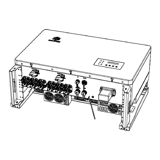
1.2 Port Description
1 2
3
2
Mechanical Installation
2.1 Installation Requirement
300 mm
150 mm
150 mm
300 mm
Warning
Do not select locations storing flammable material, which may cause fire or explosion!
2.2 Mounting
1) Drill 3 mounting holes of about
4 cm deep with a 10 mm drill bit
2) Insert expansion tubes into
holes
3) Fix the bracket on the wall with
screws
4) Hang the inverter on the
bracket
3
4
Documents
8
7
4 5678
9
0°- 15°
No.
1
2
3
4
5
6
7
8
1
4
No.
2 3
&
PV
DC
CT
Name
Ports
Switch
Port
1) A minimum 150 mm clearance should be kept
between two inverters and a minimum 300 mm
clearance between inverters and the ground.
2) Install inverter vertically or with a backward tilt
within 15°.
Description
Inverter
Wall Bracket
Expansion Screws
Fastening Screws
DC Connectors
AC Connector
WiFi/GPRS Stick
Documents
5
6
7
Commun-
COM/
Wifi/
ication
Meter
GPRS
Ports 2
/DRM
Quantity
1
1
4
3
12
Pairs
1
1
1
9
8
Ground-
AC
ing Port
Port
Advertisement

Related Manuals for Each Energy EET40-75K-M1


Summary of Contents for Each Energy EET40-75K-M1
- Page 1 Quick Installation Guide EET40-75K - M1 Overview 1.1 Scope of Delivery Description Quantity Inverter Wall Bracket Expansion Screws Fastening Screws Documents DC Connectors Pairs AC Connector WiFi/GPRS Stick Documents 1.2 Port Description 4 5678 & Commun- COM/ Ground- Wifi/ ication Meter Name ing Port...
- Page 2 Them screw up the nut tightly. the wire to the terminal block with a screwdriver. Copyright © Each Energy Technology (Suzhou) Co., Ltd. Subject to change without notice.
Need help?
Do you have a question about the EET40-75K-M1 and is the answer not in the manual?
Questions and answers