
Subscribe to Our Youtube Channel
Related Manuals for TEXIO PBW Series


Summary of Contents for TEXIO PBW Series
- Page 1 表紙 User Manual Programmable DC Regenerative Power Supply PBW Series PBW-502H PBW-502HB PBW-103HP PBW-103HS...
- Page 2 Warranty Thank you for purchasing our measuring instrument. Please read this instruction manual (hereinafter referred to as this instruction manual) carefully to the end so that you can fully demonstrate the performance of this instrument before using it. I would like to express my gratitude. Please keep this manual in a safe place.
- Page 3 ■ About a trademark, a registered trademark TEXIO is our product brand in industrial electronics. In addition, the company name and the brand name mentioned in this instruction manual are the trademark or the registered trademark of each company or group in each country and region.
-
Page 4: Table Of Contents
Table of Contents Chapter 1 Overview ............. 1 1-1. Outline of PBW series ..........1 1-1-1. Series list ............. 1 1-1-2. Operating Range ..........3 1-1-3. Features .............. 6 1-1-4. Accessories and options ........6 1-2. Part Names and Functions ......... 7 1-2-1. - Page 5 3-5. Command value/limit value setting ......29 3-6. RUN / STOP Switching ..........32 3-7. Error Reset ............... 33 Chapter 4 Series-Parallel Operation ......... 34 4-1. Series/Parallel Setting mode ........34 4-2. Series/Parallel Preparations ........35 4-2-1. Series-Parallel Wiring ........35 4-2-2.
- Page 6 7-2. Error indication ............67 Chapter 8 Specifications ........... 73 8-1. General Specifications ..........73 8-2. Terminal Specifications ..........74 8-3. Electrical Specifications ..........74 8-4. Set value specification ..........76 8-4-1. Control mode setting specifications ....76 8-4-2. Protective Value Setting Specifications ... 76 8-4-3.
- Page 7 USING THE PRODUCT SAFELY ■ Preface To use the product safely, read this instruction manual to the end. Before using this product, understand how to correctly use it. If you read this manual but you do not understand how to use it, please ask us or your local dealer.
- Page 8 USING THE PRODUCT SAFELY Warning Caution ■ Do not remove the product’s covers and panels Never remove the product’s covers and panels for any purpose. Otherwise, the user’s electric shock or fire may be incurred. ■ Warning on using the product Warning items given below are to avoid danger to user’s body and life and avoid the damage or deterioration of the product.
- Page 9 USING THE PRODUCT SAFELY ■ Warning item on Grounding If the product has the GND terminal on the front or rear panel surface, be sure to ground the product to safely use it. ■ Warnings on Installation environment ● Operating temperature and humidity Use the product within the operating temperature indicated in the “rating”...
- Page 10 USING THE PRODUCT SAFELY ■ Input / Output terminals Maximum input to terminal is specified to prevent the product from being damaged. Do not supply input, exceeding the specifications that are indicated in the "Rating" column in the instruction manual of the product. Also, do not supply power to the output terminals from the outside.
-
Page 11: Chapter 1 Overview
PBW-502H + PBW-502HB parallel model LAN CAN DIO standard PBW-103HS 10kW ±30A 1000 V PBW-502H + PBW-502H-B serial model LAN CAN DIO standard The PBW series can handle up to 100kW. For details, please contact your dealer or our company. - Page 12 About the PBW-502HB Booster Overview Booster is a device that operates as a SLAVE for series-parallel operation. SINGLE setting and operation are not possible Functional MASTER setting and operation are not possible restriction during series/parallel operation. Licenses other than serial functions and DIO functions cannot be granted.
-
Page 13: Operating Range
1-1-2. Operating Range PBW-502H Current[A] Undervoltage (30 V or less) CV/CP mode CC mode Current[A]... - Page 14 PBW-103HP (1 in series, 2 in parallel), PBW-103HS (2 in series, 1 in parallel) 1 in series, 2 in parallel 2 in series, 1 in parallel Current[A] PBW-103HP Undervoltage (30 V or less) CV/CP mode CC mode Current[A]...
- Page 15 PBW-103HS Undervoltage (30 V or less) CV/CP mode CC mode Current[A] The current in the AC → DC direction is assumed to be positive. During series-parallel operation, the number of units is multiplied by the same value. The command value and limit value can be set regardless of the operation range shown in the above figure.
-
Page 16: Features
1-1-3. Features Features Output voltage: 525 V Output current: ±30 A Configurable up to 1000V, ±600A, 100kW with series and parallel capabilities Capable of operating as a power supply and regenerative electronic load Compact and lightweight by using SiC for power devices ... -
Page 17: Part Names And Functions
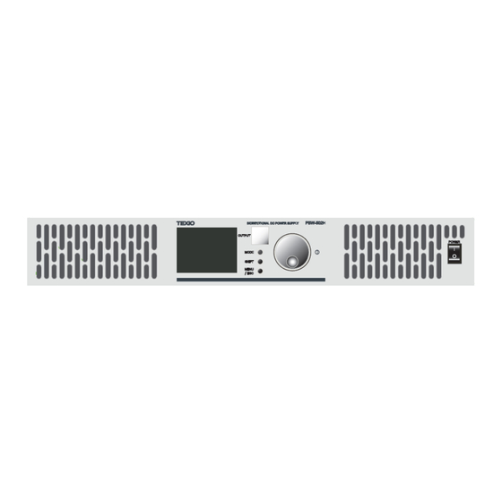
※AC input and output cables are not included. ※For PBW-103HP/HS, the housing fixing metal fittings are pre- assembled. 1-2. Part Names and Functions 1-2-1. Front Panel ② ③ ④ ① ⑦ ⑥ ⑤ ⑧ No. Name Function Press “–” to Turn on the power supply. -
Page 18: Rear Panel
Mode Switches between CV, CC, CP, button and CR modes. Switches digits when manipulating Shift button values. The key is used to switch setting MENU/ screen. It can also be used to ESC Key return to the previous screen. This is an air inlet for cooling the Air inlet fan of the internal unit. - Page 19 This terminal block port is communication used to control this device port via CAN communication. This terminal block is used Contact to control this device using input/output port contact input/output. This connector is used to control this device via LAN communication communication.
-
Page 20: Lcd Display
1-3. LCD Display Describes the display contents and operation methods of each screen displayed on the LCD. 1-3-1. Screen configuration INITIALIZE Start finished WAIT Mode WAIT 120s V.Output Voltage 0.0V 200.0V Current (V.Output 200.0V) 0.00A :Over Temperature Power :Operation Ready :Console I/F WAIT 完了... -
Page 21: Common Operation Display Contents
1-3-2. Common operation display contents Mode STOP V.Output Voltage (1) Cursor 0.0V 200.0V (2) Selected digit Current (V.Output 200.0V) 0.00A Power :Operation Ready :Console I/F Steps 1. Rotate the Knob to move the cursor through the items. Move the cursor to the item that has the value need to be changed and press Enter to change the value. - Page 22 Status name Overview AC relay DC relay WAIT Cooling wait state OPEN OPEN of the AC inrush current prevention circuit STOP Ready for operation CLOSE OPEN DC output status CLOSE CLOSE Abnormality is ERROR OPEN OPEN detected and stopped. 3. Configuration The current setting is shown on the display.
- Page 23 5. Command Value Setting Command values corresponding to each control mode are shown on the display. 6. Initialization When communication with other devices has been initiated during Parallelization/ Serialization, "Initializing" is also displayed. "Operation ready" will be shown once it is completed 7.
-
Page 24: Initialize Window
1-3-3. INITIALIZE Window Progress is indicated by a green bar. Startup in progress 1-3-4. WAIT Window The remaining waiting time is displayed. RUN and error-reset actions are disabled during WAIT. Mode xx x WAIT Remaining time 残り 待ち 時間 WAIT 120s V.Output Voltage 0.0V... -
Page 25: Run Screen
1-3-5. RUN Screen When it hits the limit value, the operation may differ from the command value. The DC output limit status is displayed when the product hits the limit value. Mode V.Output Voltage 200.0V 200.0V Current (V.Output 200.0V) 15.00A DC output restriction :Voltage upper 直流出力制限状態... -
Page 26: Error Window
1-3-6. ERROR Window The error details are displayed. When a WAIT condition occurs at the same time, the remaining waiting time will also be displayed here. Mode ERROR Remaining waiting time 残り 待ち 時間 WAIT=120s 起動処理進捗 Voltage Error Code (1) Error Code ( 1) エラ... -
Page 27: User Setting Window
1-3-7. USER SETTING window Various settings can be made. Refer to 1-3-8 “Settings hierarchy” for details. USER SETTING Protection Value 保護値設定 Protect ► Slew Rate setting ス ルーレ ート 設定 Slew Rate DC Output Resistance setting 直流出力抵抗設定 Resistance Parallel/Series setting 直並列設定... -
Page 28: Setting Hierarchy
1-3-8. Setting hierarchy Press MENU/ESC key on the WAIT, STOP, ERROR screen to move to the SETTING screen. The SETTING window allows the user to configure various settings for the device. The table below lists the hierarchy of settings. Setting items Overview Protect Protection value setting... -
Page 29: Chatper 2 Wiring
Chatper 2 Wiring This chapter describes the wiring of input/output lines. 2-1. AC Input/Protective Earth Terminal Block Steps 1. Connect the ground to the commercial three- phase system and (protective earth terminal) to the L1, L2, L3 on the AC input/protective earth terminal block on the rear panel of this device. - Page 30 Do not use the product with voltages other than the rated power supply voltage indicated on the Warning product. There is a risk of fire. Be sure to connect the protective earth terminal to earth ground. There is a risk of electric shock if the product is used without connection.
-
Page 31: Dc Output Terminal Block
2-2. DC output terminal block Steps 1. Connect the DUT to the DC output terminals of this device. Pay attention to the polarity when connecting. The direction of current and power is assumed to be positive with respect to the DC output terminal (+) →... - Page 32 被試験器へ接続します。 Connect to test device/ DUT. (Pay attention to the Poloaity) (極性に注意してください。) 電流正方向 Current positive direction 2. Turn on the power. It is ready to supply power.
-
Page 33: Chapter 3 Basic Operation
Chapter 3 Basic Operation This chapter describes the basic operations required to operate the instrument. Before operating the instrument, refer to Chapter 1, Overview, and Chapter 2, Wiring. 3-1. Protection value setting Overview Sets the protection value for the voltage and current of the DC output. - Page 34 2. Set each protection value. Press the knob to display the cursor. Use the SHIFT key to select the digit, set the protection value, and press the knob to determine it. Setting item Setting range Voltage Upper Limit 0.0V~545.0V Protective value Voltage Upper Lower -5.0V~525.0V Protective value...
-
Page 35: Slew Rate Setting
3-2. Slew rate setting Overview Set the conditions for changing to the command value or limit value during operation. Steps 1. Press the MENU/ESC key to display the USER SETTING screen. Select Slew Rate and press the knob to go to the Slew Rate Selection window. -
Page 36: Dc Output Resistance Setting
2. Enables or disables the slew rate function. 3. Valid: The selected value starts to change at a slope from (2-2) to (2- 4) after Enter also pressed. 4. Disabled: The selected value is immediately reflected when Knob is turned (it operates at the maximum inclination). - Page 37 following voltage range. 1 unit serialization: 30–525 V, 2 units serialization: 60–1000 V Steps 1. Press the MENU/ESC key to display the USER SETTING screen. Select Resistance and press the knob to go to the Run Setup window. USER SETTING Protect Slew Rate (1) Setting Value for DC Output Resistance...
-
Page 38: Setting Of The Control Mode
Setting item Setting range DC Output Resistance value 0.00Ω~100.00Ω 3. After completing, press MENU/ESC key or select Return to return to the previous page. It is not possible to change the settings while device is operating. Note 3-4. Setting of the control mode Overview CV/CC/CP/CR can be changed. -
Page 39: Command Value/Limit Value Setting
MODE Mode Mode Mode STOP STOP STOP V.Output Voltage C.Output Voltage P.Output Voltage MODE MODE 0.0V 0.0V 0.0V 200.0V 10.00A 1000W Current Current Current (V.Output 200.0V) (C.Output 10.00A) (P.Output 1000W) 0.00A 0.00A 0.00A Power Power Power :Operation Ready :Operation Ready :Operation Ready :Console I/F :Console I/F... - Page 40 depends on the slew rate function setting. Please refer to 3-2 Slew rate setting for the setting method. Steps 1. Select the setting item and press the knob to display the cursor on the setting value. 2. Select the digit with the SHIFT key, and press the knob to determine it.
- Page 41 Upper limit of 0.80A~32.00A×Parallel current limit value number Lower limit of -32.00A ~-0.80A×Parallel current limit value number Uppwer limit of 200W~5300W× power limit value Series/parallel number Lower limit of -5300W~-200W× power limit value Series/parallel number Since the limit value takes precedence over the command value, it may not follow the command Note value.
-
Page 42: Run / Stop Switching
3-6. RUN / STOP Switching Steps 1. When Output key is in STOP status, it lights up in yellow, and the DC relay begins to close. When the DC relay is closed, it illuminates in green to move to the RUN states. Press Start/Stop again to return to STOP mode. -
Page 43: Error Reset
3-7. Error Reset Steps 1. In ERROR status, Output key lights will be in red. In ERROR mode 2. Remove the cause and press the rotary encoder knob to reset. It cannot be reset in the WAIT state. Reset after Note WAIT is completed. -
Page 44: Chapter 4 Series-Parallel Operation
Chapter 4 Series-Parallel Operation This device can construct a system in which voltage range and current capacity are expanded by connecting multiple units in series and parallel. A maximum of 2 series and a maximum of 20 parallel connections are possible. However, in the case of series/parallel, it is limited to 2 series/10 parallel. -
Page 45: Series/Parallel Preparations
It operates according to the Slave instruction of the master in series and parallel. USER SETTING Multiple (5) Parallel/Serial Mode selection (2 - 1) 直並列モード選択 Mode : Slave ► (2 - 2) SNUM / SID Series No (6) Serial ID (7) Parallel ID (2 - 3) PSUM / PID Parallel No... - Page 46 PBW-103HS is already in series configuration. Note Therefore, two PBW-103HS cannot be used and connected in series. Two series and three parallel connection example About the slave device ID SID: Series connection ID 1st column (lower voltage) = 1 2nd column (upper voltage) = 2 PID: Parallel connection ID 1 to 20 (10: when including series) For details, please refer to 4-2-2 Series/parallel...
-
Page 47: Series/Parallel Setting Procedure
fashion using the supplied LAN cable (orange wire in Fig. above). 5. Connect the supplied terminating resistors to both ends of the cable. If the supplied cable (0.25 m) is not long enough, use a straight cable with CAT5e or more. The total Note length of the daisy-chain connection must not exceed 20 m. - Page 48 4. For the master, set the Sereis No. (Total number of serial units) and Parallel No. (Total number of parallel units). For slaves, set their Sereis ID and Parallel ID. Sereis No. For master Parallel No. 1~20(10:Including series) Sereis ID 1st column in series(Lower For slave voltage)=1...
- Page 49 Example) USER SETTING Setting screen Protect Slew Rate Resistance (1) Parallel/Serial setting (1) 直並列設定 Multiple ► Interface Product Info Enter USER SETTING Multiple (2-1) Parallel/Serial Mode selection (2 - 1) 直並列モード選択 Mode : Master ► (2 - 2) SNUM / SID Series No (2-2) SNUM/SID (2 - 3) PSUM / PID...
- Page 50 7. The master is appended with “-M” at the end of the control mode. The slave displays “SLAVE” in the control mode. The serial- to-parallel ID of its own unit is displayed in the field of the command value or limit value. 8.
- Page 51 Example) Mode Mode CV-M STOP SLAVE STOP Series/Parallel Series Parallel V.Output Voltage Voltage 0.0V 0.0V Setting 200.0V Current Current Procedure (V.Output 200.0V) 0.00A 0.00A Power Power :Initializing... :Initializing... :Console I/F :Console I/F (4) 直並列通信初期化完了 Parallel/Serial communication initialization completed Mode Mode CV-M STOP SLAVE...
- Page 52 During series and parallel operation, the whole operation can be operated at once with Master. Note Master setting is equally divided and set to Slave. The measured value of Master displays the DC output value in series and parallel. The measured value of Slave displays the DC output value of the device.
-
Page 53: Chapter 5 Various Settings
Chapter 5 Various Settings This chapter describes interface selection and various settings. 5-1. Interface Selection Overview Select the interface to use to operate this device. Steps 1. Press the MENU/ESC key to display the USER SETTING screen. Select Interface and press the knob to go to the Setting window. -
Page 54: Console Setting
5-2. Console Setting The device can be operated or displayed through the front panel. 5-2-1. LCD backlight adjustment Overview LCD brightness can be adjusted. Steps 1. Press the MENU/ESC key to display the USER SETTING screen. Select Interface and press the knob to go to the Setting window. -
Page 55: Panel Display Direction
5-2-2. Panel display direction Overview LCD display rotation can be adjusted. 1. Press the MENU/ESC key to Steps display the USER SETTING screen. Select Interface and press the knob to go to the Setting window. 2. Select Console and press the knob to go to the settings screen. -
Page 56: Can Setting
5-3. CAN setting CAN setting is possible. See the programming manual for details. The programming manual can be downloaded from our website. https://www.texio.co.jp 5-3-1. CAN Config Overview Set CAN IDs. USER SETTING Protect Interface Select Console Slew Rate (2) CAN Transmission setting ( 2) CAN設定... -
Page 57: Can Communication
1. Press the MENU/ESC key to Steps display the USER SETTING screen. Select Interface and press the knob to go to the Setting window. 2. Select CAN Config and press the knob to go to the configuration screen. 3. Press the knob to select CAN ID Range. - Page 58 USER SETTING Protect Interface Select Console Slew Rate CAN Config (2) CAN Transmission setting ( 2) CAN通信設定 Resistance CAN Communication ► LAN Config Multiple LAN Communication (1) Interface setting Interface ( 1) イ ン タ ーフ ェ ース 設定 ► Product Info En ter USER SETTING...
- Page 59 5. Press the knob to select [Regular Transmit]Time. 6. Use the rotary encoder and SHIFT key to set the periodic transmission period and press the knob to confirm. Time Range Transmission period 10~10,000ms 7. Press the knob to select[Time Out]Function. 8.
-
Page 60: Lan Setting
5-4. LAN Setting LAN setting is possible. See the programming manual for details. The programming manual can be downloaded from our website. https://www.texio.co.jp 5-4-1. LAN Config Overview Set the LAN IP Address and Subnet mask. USER SETTING Protect Interface Select... -
Page 61: Lan Communication
3. Press the knob to select IP address. 4. Use the rotary encoder and SHIFT key to set the IP address, and press the knob to confirm. 5. Press the knob to select Subnet mask. 6. Use the rotary encoder and SHIFT key to set the Subnet mask, and press the knob to confirm. - Page 62 USER SETTING Protect Interface Select Console Slew Rate CAN Config Resistance CAN Communication LAN Config (2) LAN Transmission setting Multiple ( 2) LAN通信設定 LAN Communication ► (1) Interface setting Interface ► ( 1) イ ン タ ーフ ェ ース設定 Product Info En ter USER SETTING LAN Communication...
- Page 63 5. Press the knob to select [Regular Transmit]Time. 6. Use the rotary encoder and SHIFT key to set the periodic transmission period and press the knob to confirm. Time Range Transmission period 10~10,000ms 7. Press the knob to select [Time Out]Function.
-
Page 64: Dio
5-5. DIO Emergency stop input and error detection signal output can be performed by contact. 5-5-1. DIO terminal By using this function, it is possible to input an Overview external emergency stop using DIO and output a signal when an error is detected. This function must be enabled when using the DIO pin. - Page 65 DO0_IN Error detection signal output, non-voltage contact, open when detected DO0_OUT DO1_IN Reserved DO1_OUT Inside the device Outside the device Pressing (a) to activate an external emergency stop. Since it is a no-voltage contact output, (b) lights up by using a relay like the one on the right.
-
Page 66: Dio Function Setting
5-5-2. DIO Function Setting Enables or disables the emergency stop input at Overview contact input. USER SETTING Protect Interface Select Console Slew Rate CAN Config Resistance CAN Communication LAN Config Multiple LAN Communication ( 2 ) D I O設定 (2) DIO setting ►... - Page 67 Fuction Description Enable DIO is enabled Disable DIO is disabled 5. Select return or press the MENU/ESC key to return to the previous screen. Mode Mode Reset Steps ERROR STOP Error Code Voltage V.Output Voltage :0x02000000+00 0.0V 0.0V 200.0V Emergency stop Current Current Enter...
-
Page 68: Chapter 6 Product Information
Chapter 6 Product Information This chapter describes how to check and update the model number of this unit, version information, initialization, etc. 6-1. Device information Model and Version of the device can be Overview identified. (2) About (Device information) ► (1) Product information ►... -
Page 69: License Information
6-2. License Information Overview The license can be checked. USER SETTING Protect About (2) License information (2) ライセンス 情報 License ► Slew Rate Activation Resistance Update Multiple Interface (1) Product information Product Info (1) 製品情報 ► Enter USER SETTING License Permanent Return ►... -
Page 70: Firmware Update
LAN. For the latest firmware information, please contact your dealer or our sales office. The dedicated application can be downloaded from our website. https://www.texio.co.jp Series-parallel operation is not possible between Note devices equipped with different firmware versions. Steps 1. Connect the PC and the device with a LAN cable. - Page 71 2. (2-1) Select the Update Firmware tab on top. (2-2) Select the IP address of the PC connected to the LAN (2-3) Enter the IP address of this device. (2-4) Please set the path of the update firmware file (.hfi). (2-1) License update ( 2-1) フ...
- Page 72 (6) Initiate download ( 6 ) ダウン ロ ード 開始 7. Receiving update firmware from PC. Never turn off the power of this equipment during reception. 8. Check the firmware version after rebooting. Please refer to 6-1 Device information for how to check the version.
-
Page 73: Initialization Setting
6-4. Initialization Setting Overview Command Value, Protective Value, Parallel/Serialization setting, LAN, and CAN initial value setting. License details are retained, and a system reboot is needed. Rebooting is required. USER SETTING (1) Initialization ( 1) 設定値初期化 Factory Reset ► En ter USER SETTING Factory Reset All of the config will be... - Page 74 Steps 1. Press the MENU/ESC key to display the USER SETTING screen. Select Factory Reset and press the knob to go to the Setting window. 2. Select I agree and press the knob. If you do not want to initialize, select Cancel or press the MENU/ESC key.
-
Page 75: Chapter 7 Others
Chapter 7 Others This chapter describes how to check failures and what to do when errors occur. 7-1. Troubleshooting Overview If any trouble or problem is suspected during use of this device, check the product referring to the following items. If there is no item applicable to the symptom or if the problem is not resolved by taking countermeasures, contact your supplier or our... - Page 76 DC output is not The command value and Set an appropriate output. limit value are set to 0. value to the command value and limit value. Stable with DC Limited by either the set Check the DC output voltage/current/ value of DC limit status.
-
Page 77: Error Indication
7-2. Error indication An error code is displayed at ERROR. The details of each bit are described in the table below. An optional error display is displayed to the right of the +. Please remove the cause of the error by referring to the countermeasure column. - Page 78 0x00000008 Countermeasure EEPROM error: EEPROM error EEPROM read/write error 0x00000010 SW error 1 Countermeasure Software error 1 0x00000020 Countermeasure Internal voltage error 3: Hardware error 3 Abnormal voltage of the internal bus of the system 0x00000040 Reserved Error 0x00000080 Countermeasure DC overvoltage:...
- Page 79 0x00008000 AC overcurrent Countermeasure OVR AC (Peak instantaneous value: value) Instantaneous overvoltage of AC input 0x00010000 AC overvoltage rms Countermeasure OVR AC (RMS value:Rms value value) overvoltage of AC input 0x00020000 AC overcurrent Countermeasure OCR AC (Peak instantaneous value: value) Instantaneous overcurrent of AC input 0x00040000...
- Page 80 0x04000000 Reserved Error 0x08000000 Reserved Error 0x10000000 Countermeasure Series-parallel error: Multiple setting Anomaly in series- problem parallel settings 0x20000000 SW error 2 Countermeasure Software error 2 0x40000000 SW error 3 Countermeasure Software error 3 0x80000000 Series/Parallel Other Check the error Other machine indications of Device Error:...
- Page 81 Reserved Reserved Reserved Corrective action Error handling method This may occur because of the value of AC input voltage or frequency. Check the input wiring. Refer to 8-3 Electrical specifications for input specifications, and 2-1 AC input/protective ground wiring for connection methods. This may occur depending on the setting of the protection value.
- Page 82 there is a possibility of false detection of an abnormal state due to noise in the operating environment. This may have occurred because of the transient changes in the UUT or the control performance of this device. Consider taking the following actions according to the timing of occurrence.
-
Page 83: Chapter 8 Specifications
Chapter 8 Specifications This chapter describes each specification. 8-1. General Specifications Item Specifications Remarks Operating temperature range 0~40℃ Accuracy guaranteed 25±5℃ temperature range Humidity range 20~80%RH No condensation PBW-502H W430×D670×H66 mm Excluding Size protrusions PBW-103HP/HS W430×D670×H132 mm PBW-502H 18kg Weight PBW-103HP/HS 38kg Primary - Secondary Dielectric strength... -
Page 84: Terminal Specifications
8-2. Terminal Specifications Item Form Remarks Terminal AC Input Rated 600 V to 50 A block M4 screw fixing/4P, 13 mm-pitch Grounding DC output Terminal Rated 600 V to 50 A block M4 screw fixing/4P, 13 mm-pitch ※ Series-parallel LINK IN RJ45 Dedicated signal communication... - Page 85 Maximum efficiency 92% 1 series 2 series For details, DC output Series please refer to 0.0 ~ 0.0 ~ Voltage range 1-1-2 Operating 525.0V 1000.0V Range. ± 30.0A x Number Current range of Parallels ± 5.0kW x Power range Series/Parallel Number ※1,※2 Voltage Accuracy...
-
Page 86: Set Value Specification
※1 Accuracy guaranteed temperature ※2 DC output voltage (30 x series number) V or more ※3 Resistive load ※4 Time when DC output voltage changes by 10 → 90% with respect to a change in command value of the resistive load, 30 → 525 V or 525 →, 30 V ※5 Time when DC output changes by 10 →90% with respect to a change in command value of the voltage source, ±100% F.S. -
Page 87: Command Value Setting Specifications
1 series: 525V Voltage -5.0V × Series 2 series: 1000V protection value -5.0V number or voltage protection lower limit value upper limit Current 1.10A × Number 33.00A × Number of protection value 33.00A of Parallels Parallels upper limit Current -33.00A × -1.10A ×... -
Page 88: Slew Rate Setting Specifications
Current limit -32.00A ×Number -0.80A × Number value lower -32.00A of Parallels of Parallels limit Power limit 200W × 5300W × upper limit 5300W Series/Parallel Series/Parallel Number Number Power limit -5300W × -200W × lower limit -5300W Series/Parallel Series/Parallel Number Number Voltage 0.4%F.S. -
Page 89: Series/Parallel Setting Specifications
8-4-7. Series/Parallel Setting Specifications Item Initial value Minimum value Maximum value Series-parallel mode SINGLE SINGLE / MASTER / SLAVE SNUM / SID 1 series: 20 PNUM / PID 2 series: 10... -
Page 90: Dimensions
8-5. Dimensions PBW-502H scale:mm Booster is also the same size. For PBW-103Hx, except for the legs, it will be stacked in two layers. It also has a cover on the back. - Page 91 7F Towa Fudosan Shin Yokohama Bldg., 2-18-13, Shin Yokohama, Kohoku- ku, Yokohama, Kanagawa, 222-0033, Japan. https://www.texio.co.jp/ For after-sales service, please visit the service center below. service center 〒222-0033 8F Towa Fudosan Shin Yokohama Bldg., 2-18- 13, Shin Yokohama, Kohoku-ku, Yokohama TEL.045-620-2786...
Need help?
Do you have a question about the PBW Series and is the answer not in the manual?
Questions and answers