
Related Manuals for TEXIO PR-A Series


Summary of Contents for TEXIO PR-A Series
- Page 1 INSTRUCTION MANUAL REGULATED DC POWER SUPPLY PR-A SERIES PR18-1.2A PR18-3A PR18-5A PR36-3A B71-0040-01...
- Page 2 ■ About Brands and Trademarks “TEXIO” is the product brand name of our industrial electronic devices. All company names and product names mentioned in this manual are the trademark or the registered trademark of each company or group in each country and region.
-
Page 3: Table Of Contents
CONTENTS SAFETY ································································· Ⅰ -Ⅳ 1. OUTLINE ..................1 2. FEATURES ................. 1 3. SPECIFICATION ................. 2 4. PERCAUTION FOR USE ............4 5. EXPLANATION OF PANELS ............5 5-1. Front panel ....................6 5-2. Rear panel ..................... 7 6. OPERATION PROCEDURES ............. 8 6-1. - Page 4 USING THE PRODUCT SAFELY ■ Preface To use the product safely, read instruction manual to the end. Before using this product, understand how to correctly use it. If you read the manuals but you do not understand how to use it, ask us or your local dealer. After you read the manuals, save it so that you can read it anytime as required.
- Page 5 USING THE PRODUCT SAFELY CAUTION WARNING ■ Do not remove the product's covers and panels Never remove the product's covers and panels for any purpose. Otherwise, the user's electric shock or fire may be incurred. ■ Warning on using the product Warning items given below are to avoid danger to user's body and life and avoid the damage or deterioration of the product.
- Page 6 USING THE PRODUCT SAFELY ■ Warning item on Grounding If the product has the GND terminal on the front or rear panel surface, be sure to ground the product to safely use it. ■ Warnings on Installation environment ● Operating temperature and humidity Use the product within the operating temperature indicated in the “rating”...
- Page 7 USING THE PRODUCT SAFELY ■ Input / Output terminals Maximum input to terminal is specified to prevent the product from being damaged. Do not supply input, exceeding the specifications that are indicated in the "Rating" column in the instruction manual of the product. Also, do not supply power to the output terminals from the outside.
-
Page 8: Outline
1. OUTLINE The PR-A Series is a serial control type regulated DC power supply. It is a constant voltage/current power supply whose output can be varied from 0 up to the rated values. It is a compact unit which, provided with both voltage and current calibrated meters, allows both voltage and current to be monitored simultaneously. -
Page 9: Specification
3. SPECIFICATION Item PR18-1.2A PR18-3A PR18-5A PR36-3A Output Voltage 0V to 18V 0V to 36V (continuously variable、coarse and fine adjusts) Output current(continuously variable) 0A to 1.2A 0A to 3A 0A to 5A 0A to 3A Constant voltage characteristics Input fluctuation ( for surge of AC±100%) 0.01%+2mV(3.8mV)... - Page 10 Item PR18-1.2A PR18-3A PR18-5A PR36-3A Function OUTPUT ON / OFF switching Turn the output on and off. Can be connected in series (within limits of ground proof voltage.) Serial connection (independent control mode) Can be operated in “one‐control” parallel configuration (only with other machines of same model) Parallel operation (master-slave mode)...
-
Page 11: Percaution For Use
4. PERCAUTION FOR USE WARNING 1) Confirming the supply voltage *Use this unit within the specified range. The unit’s rated voltage is single-phase 100/120/200/220/240VAC ±10% at 50/60Hz. *The rated voltage is indicated on the specification and name plate located beside the input connector on the rear panel. 2) Do not remove cover or panel The user never open the case panel whatever may happen. -
Page 12: Explanation Of Panels
5. EXPLANATION OF PANELS Figure1. Figure2. -
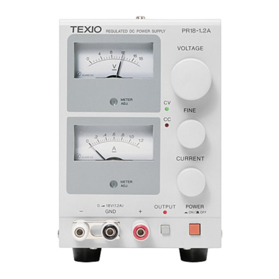
Page 13: Front Panel
5-1. Front panel ①POWER ON/OFF The power switch. The power supply should be on and operating when this switch is depressed. ②OUTPUT switch Turns the output on and off. When the output is turned on, the OUTPUT LED goes on. ③Voltmeter A DC voltmeter that indicates the output voltage. -
Page 14: Rear Panel
5-2. Rear panel ⑭MASTER/SLAVE switch Used during “one-control” parallel operation in the master/slave configuration. During normal operation, the switch should be set to MASTER. (For details, see section 6-3;“Parallel Operation” ) ⑮IN/OUT terminals for parallel operation Control terminals for use in the “one-control” parallel operation mode. ⑯Power cable Approx. -
Page 15: Operation Procedures
6. OPERATION PROCEDURES 6-1. Stand-alone operation *When using the power supply in stand-alone, simply operate by manipulation of the panel switches as needed. However , be sure that the MASTER/SLAVE switch is set to MASTER. 6-2. Serial connection *Two or more units of the power supply can be hooked up in series to achieve in increase in output voltage. -
Page 16: Parallel Operation (Master-Slave Control)
6-3. Parallel operation (master-slave control) *Two or more units of the same machine can be hooked up in parallel to give an increase in output current. The total output current will be the sum of the output currents of the individual machines. *In parallel operation, one machine will act as the master and all others will act slaves. - Page 17 Hook-up front panel terminals in the parallel operation modes. MASTER SLAVE(1) SLAVE(2) Note ; I The voltage presets on all the slave machines are set to maximum. The master operates in constant voltage mode and the slaves operate in constant current mode.
-
Page 18: Troubleshooting
7. TROUBLESHOOTING Problem Indicators or Areas to check Cause *Poor connection of Power supply will Power ON lamp does not light not go on. power cord, or broken wire. *Bad power switch. *Fuse meltdown. *Circuit malfunction. No output voltage. Voltmeter does not move. *Circuit malfunction. - Page 19 7F Towa Fudosan Shin Yokohama Bldg. 2-18-13, Shin Yokohama, Kohoku-ku,Yokohama, Kanagawa, 222-0033 Japan http://www.texio.co.jp/...
Need help?
Do you have a question about the PR-A Series and is the answer not in the manual?
Questions and answers