Table of Contents
Advertisement
Quick Links
Advertisement
Table of Contents

Subscribe to Our Youtube Channel
Related Manuals for TEXIO PU Series


Summary of Contents for TEXIO PU Series
- Page 1 INSTRUCTION MANUAL 750W SERIES DC POWER SUPPLY PU SERIES PU6-100 6V/100A PU8-90 8V/90A PU12.5-60 12.5V/60A PU20-38 20V/38A PU30-25 30V/25A PU40-19 40V/19A PU60-12.5 60V/12.5A PU80-9.5 80V/9.5A PU100-7.5 100V/7.5A PU150-5 150V/5A PU300-2.5 300V/2.5A PU600-1.3 600V/1.3A B71-0128-00...
- Page 2 ■ About Brands and Trademarks TEXIO is the product brand in the industrial-use electronics equipment of our company. The company and product names described in this manual are the brands and trademarks owned by the respective companies or organizations in each country and region.
-
Page 3: Table Of Contents
CONTENTS USING THE PRODUCT SAFELY .................... Ⅰ~Ⅲ 1. GENERAL INFORMATION ____________________________________________________ 1 1-1. Features and options........................1 1-2. Analog voltage programming and monitoring ..................1 1-3. Control via the serial communication port..................1 1-4. Output connections...........................2 1-5. Cooling and mechanical construction ....................2 1-6. Models covered by this manual......................2 2. - Page 4 2-10-9. Connecting multiple loads, radial distribution method..............12 2-10-10. Multiple load connection with distribution terminals ..............12 2-10-11. Grounding outputs.......................... 12 2-11. Local and remote sensing ......................13 2-11-1. Local sensing ............................ 13 2-11-2. Remote sensing..........................14 2-11-3. J2 sense connector technical information ..................14 3.
- Page 5 4-14. Parallel operation..........................28 4-14-1. Parallel operation (1) ........................28 4-14-2. Parallel operation (2) ........................29 4-15. Daisy-chain connection ........................30 4-16. Front panel locking ........................31 4-16-1. Unlocked front panel......................... 31 4-16-2. Locked front panel ..........................31 5. REMOTE ANALOG PROGRAMMING___________________________________________ 32 5-1.
- Page 6 6-7-1. Conditional registers........................... 47 6-7-2. Service Request: Enable and Event Registers................48 6-8. Serial communication test set-up ....................49 7. ISOLATED ANALOG PROGRAMMING OPTION __________________________________ 50 7-1. Specifications ..........................50 7-1-1. 0V to 5V/0V to 10V option........................50 7-1-2. 4mA to 20mA option........................... 50 7-2.
-
Page 7: Using The Product Safely
USING THE PRODUCT SAFELY ■ Preface To use the product safely, read instruction manual to the end. Before using this product, understand how to correctly use it. If you read the manuals but you do not understand how to use it, ask us or your local dealer. After you read the manuals, save it so that you can read it anytime as required. - Page 8 USING THE PRODUCT SAFELY ■ Do not remove the product's covers and panels Never remove the product's covers and panels for any purpose. Otherwise, the user's electric shock or fire may be incurred. ■ Warning on using the product Warning items given below are to avoid danger to user's body and life and avoid the damage or deterioration of the product.
- Page 9 USING THE PRODUCT SAFELY ■ Do not let foreign matter in Do not insert metal and inflammable materials into the product from its vent and spill water on it. Otherwise, electric shock or fire may occur. ■ Warning item on abnormality while in use If smoke or fire is generated from the product while in use, stop using the product, turn off the switch, and remove the power cord plug from the outlet.
-
Page 11: General Information
◆ Refer to User Manual for Power Supply GP-IB programming Interface. PU power supplies are wide output range, high performance switching power supplies. The PU series is power factor corrected and operates from worldwide AC voltage range continuously. Output voltage and current are continuously displayed and LED indicators show the complete operating status of the power supply. -
Page 12: Output Connections
1-5. Cooling and mechanical construction The PU series is cooled by internal fans. At the installation, care must be taken to allow free airflow into the power supply via the front panel and out of the power supply via the rear panel. The PU power supplies have a compact and lightweight package, which allows easy installation and space saving in the application equipment. -
Page 13: Prior To Use
2. PRIOR TO USE 2-1. Initial inspection Prior to shipment this power supply was inspected and found free of mechanical or electrical defects. Upon unpacking of the power supply, inspect for any damage, which may have occurred in transit. The inspection should confirm that there is no exterior damage to the power supply such as broken knobs or connectors and that the front panel and meters face are not scratched or cracked. -
Page 14: Rack Mounting
+50 °C 2-7. AC source requirements The PU series can be operated from a nominal 100V to 240V, single phase, 47Hz to 63Hz. ◆ The input voltage range and current required for each model is specified in "APPENDIX C SPECIFICATIONS". -
Page 15: Turn-On Checkout Procedure
2-9. Turn-on checkout procedure The following procedure ensures that the power supply is operational and may be used as a basic incoming inspection check. Refer to Fig.3-1 and Fig.3-2 for the location of the controls indicated in the procedure. 2-9-1. Prior to operation 1. -
Page 16: Ovp Check
2-9-4. OVP check ◆ Refer to "4-2. Over voltage protection (OVP)". 1. Turn the front panel AC power switch to On position and turn on the output by pressing OUTPUT pushbutton. 2. Using the VOLT encoder, adjust the output voltage to approx.10% of the unit voltage rating. 3. -
Page 17: Connecting The Load
2-10. Connecting the load urn off the AC input power before making or changing any rear panel connection. Ensure that all connections are securely tightened before applying power. There is a potential shock hazard when using a power supply with a rated output greater than 40V. -
Page 18: Wire Termination
2-10-3. Wire termination The wires should be properly terminated with terminals securely attached. DO NOT use unterminated wires for load connection at the power supply. When local sensing, a short from +LS or +S to -V or -S or -LS, will cause damage to the power supply. -
Page 19: Making The Load Connections
2-10-6. Making the load connections Hazardous voltages exist at the outputs and the load connections when using a power supply with a rated output greater than 40V. To protect personnel against accidental contact with hazardous voltages, ensure that the load and its connections have no accessible live parts. - Page 20 80V to 600V Models Hazardous voltages exist at the outputs and the load connections. To protect personnel against accidental contact with hazardous voltages, ensure that the load and its connections have no accessible live parts. Ensure that the load wiring insulation rating is greater than or equal to the maximum output voltage of the power supply.
-
Page 21: Connecting Single Loads, Local Sensing (Default)
2-10-7. Connecting single loads, local sensing (default) Fig.2-7 shows recommended load and sensing connections for a single load. The local sense lines shown are default connections at the rear panel J2 sense connector. Local sensing is suitable for applications where load regulation is less critical. -
Page 22: Connecting Multiple Loads, Radial Distribution Method
2-10-9. Connecting multiple loads, radial distribution method Fig.2-9 shows multiple loads connected to one supply. Each load should be connected to the power supply’s output terminals using separate pairs of wires. It is recommended that each pair of wires will be as short as possible and twisted or shielded to minimize noise pick-up and radiation. -
Page 23: Local And Remote Sensing
2-11. Local and remote sensing The rear panel J2 sense connector is used to configure the power supply for local or remote sensing of the output voltage. Refer to Fig.2-11 for sense connector location. Fig.2-11: Sense connector location There is a potential shock hazard at the sense connector when using a power supply with a rated output voltage greater than 40V. -
Page 24: Remote Sensing
2-11-2. Remote sensing There is a potential shock hazard at the sense point when using power supply with a rated output voltage greater than 40V. Ensure that the connections at the load end are shielded to prevent accidental contact with hazardous voltages. When using shielded sense wires, ground the shield in one place only. -
Page 25: Front And Rear Panel Controls And Connectors
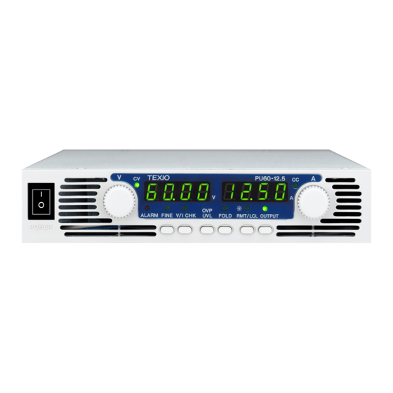
3. FRONT AND REAR PANEL CONTROLS AND CONNECTORS 3-1. Front panel controls and indicators See Fig.3-1 to review the controls, indicators and meters located on the power supply front panel. Fig.3-1: Front panel controls and indicators (PU60-12.5 Model) 1. AC power switch - AC On/Off control. - Page 26 14. OUTPUT button - Main function: Output ON/OFF control. Press OUTPUT to set the output On or OFF. Press to reset and turn On the output after OVP or FOLD alarm events have occurred. ◆ Refer to "4-5. Output ON/OFF control".
-
Page 27: Rear Panel
3-2. Rear panel Fig.3-2: Rear panel connections and controls (PU60-12.5 Model) 20. AC input connector - IEC connector ◆ Refer to "2-8-1. AC input connector". 21. DC output 6V to 60V output model 80V to 600V output model - Bus-bars for 6V to 60V models. - Wire clamp connector for 80V to 600V models. -
Page 28: Sw1 Setup Switch
3-3. SW1 setup switch The SW1 Setup switch (see Fig.3-3) is a 9-position DIP switch that allows the user to choose the following: - Internal or remote programming for Output Voltage and Current Limit. - Remote voltage or resistive programming of Output Voltage and Output Current limit. - Select range of remote voltage and resistive programming. -
Page 29: J1 Programming And Monitoring Connector
3-4. J1 programming and monitoring connector The J1 Programming and Monitoring connector is a DB25 subminiature connector located on the power supply rear panel. ◆ Refer to Table 4-4 for description of the connector functions. The power supply default configuration is Local operation, which does not require connections to J1. For remote operation using J1 signals use the plug provided with power supply or equivalent type. - Page 30 Fig.3-4: J1 connector terminals and functions Table 3-2: J1 connector terminals and functions J1 contact Signal name Function Enable/Disable the power supply output by dry-contact (short/open). J1-1 ENA_IN ◆ Refer to "4-7. ENABLE/DISABLE control via rear panel J1 connector". Isolated Interface Common. Return for the SO control, PS_OK signal and for the J1-2 optional GP-IB interface.
-
Page 31: Local Operation
4. LOCAL OPERATION This Chapter describes the operating modes that are not involved in programming and monitoring the power supply via its serial communication port (RS232/RS485) or by remote analog signals. Ensure that the RMT/LCL on the front panel is off, indicating Local mode. If the RMT/LCL LED is on, press the front panel RMT/LCL button to change the operating mode to local. -
Page 32: Over Voltage Protection (Ovp)
4-2. Over voltage protection (OVP) The OVP circuit protects the load in the event of a remote or local programming error or a power supply failure. The protection circuit monitors the voltage at the power supply sense points and thus providing the protection level at the load. -
Page 33: Foldback Protection
4-4. Foldback protection Foldback protection will shut down the power supply output if the load current exceeds the current limit setting level. This protection is useful when the load circuitry is sensitive to an over current condition. 4-4-1. Setting the Foldback protection To arm the Foldback protection, the FOLD button should be pressed so that the FOLD LED illuminates. -
Page 34: Output Shut-Off (So) Control Via Rear Panel J1 Connector
4-6. Output SHUT-OFF (SO) control via rear panel J1 connector Contacts 2, 3 and 15 of J1 (Fig.3-2, Item 24) serve as Output Shut-Off (SO) terminals. The SO terminals accept a 2.5V to 15V signal or Open-Short contact to disable or enable the power supply output. The SO function will be activated only when a transition from On to Off is detected after applying AC power to unit.(Thus, in Auto-Restart mode, the output will be enabled after applying AC power, even if SO is in Off level.). -
Page 35: Cv/Cc Signal
4-8. CV/CC signal CV/CC signal indicates the operating mode of the power supply, Constant Voltage or Constant Current. CV/CC signal is an open collector output with a 30V parallel zener, at J1-13, referenced to the COM potential at J1-12 (connected internally to the negative sense potential). When the power supply operates in Constant Voltage mode, CV/CC output is open. -
Page 36: Last Setting Memory
4-12. Last setting memory The power supply is equipped with Last Setting Memory, which stores power supply parameters at each AC turn-off sequence. STOREDPARAMETERS: 1. Output voltage setting 2. Output current setting 3 .OVP level 4. UVL level 5. FOLD setting 6. -
Page 37: Series Connection For Positive And Negative Output Voltage
Remote programming in series operation for increased output voltage: 1. Programming by external voltage: The analog programming circuits of this power supply are referenced to the negative Sense (-S) potential. Therefore, the circuits used to control each series connected unit must be separated and floated from each other. 2. -
Page 38: Parallel Operation
4-14. Parallel operation 4-14-1. Parallel operation (1) Up to four units of the same VOLTAGE and CURRENT rating can be connected in parallel to provide up to four times the output current capability. One of the units operates as a master and the remaining units are slaves. The slave units are analog programmed by the master unit. -
Page 39: Parallel Operation (2)
4-14-2. Parallel operation (2) In this method, multiple supplies can be configured to parallel operation as a single power supply. The total load current and output voltage are displayed by the Master unit and can be readback from the Master unit. The Slave units display only their operating status (ON, OFF or Fault condition). -
Page 40: Daisy-Chain Connection
Fig.4-4: Parallel connection with local sensing Fig.4-5: Parallel operation with Remote sensing 4-15. Daisy-chain connection It is possible to configure a multiple power supply system to shut down all the units when a fault condition occurs in one of the units. When the fault is removed, the system recovers according to its setting to Safe start mode or Automatic restart. -
Page 41: Front Panel Locking
4-16. Front panel locking The front panel controls can be locked to protect from accidental power supply parameter change. Press and hold V/I CHK button to toggle between “Locked front panel” and “Unlocked front panel”. The display will cycle between “LFP” and “UFP”. Releasing the V/I CHK button while one of the modes is displayed, selects that mode. -
Page 42: Remote Analog Programming
5. REMOTE ANALOG PROGRAMMING The rear panel connector J1 allows the user to program the power supply output voltage and current limit with an analog device. J1 also provides monitoring signals for output voltage and output current. The programming range and monitoring signals range can be selected between 0V to 5V or 0V to 10V using the setup switch SW1. -
Page 43: Remove Voltage Programming Of Output Voltage And Current Limit
5-3. Remove voltage programming of output voltage and current limit To maintain the isolation of power supply and prevent ground loops, use an isolated programming source when operating the power supply via remote analog programming at J1 connector. Perform the following procedure to set the power supply to Remote Voltage programming : 1. -
Page 44: Resistive Programming Of Output Voltage And Current
5-4. Resistive programming of output voltage and current For resistive programming, internal current sources, for output voltage and/or output current control, supply 1m acurrent through external programming resistors connected between J1-9 & 22 and 1-10 & 23. The voltage across the programming resistors is used as a programming voltage for the power supply. -
Page 45: Remote Monitoring Of Output Voltage And Current
5-5. Remote monitoring of output voltage and current The J1 connector, located on the rear panel provides analog signals for monitoring the output voltage and output current. Selection of the voltage range between 0V to 5V or 0V to 10V is made by setup switch SW1-4. The monitoring signals represent 0% to 100% of the power supply output voltage and output current. -
Page 46: Rs232 & Rs485 Remote Control
6. RS232 & RS485 REMOTE CONTROL This chapter describes the operation of the PU750W power supplies via the serial communication port. Details of the initial set-up, operation via RS232 or RS485, the command set and the communication protocol are described in this chapter. -
Page 47: Rs232/485 Port In Local Mode
6-1-6. RS232/485 port in Local mode When the power supply is in local mode, it can receive queries or commands. If a query is received, the power supply will reply and remain in Local mode. If a command that affects the output is received, the power supply will perform the command and change to Remote mode. - Page 48 DB-25 connector 8 Pin connector Remarks Pin No. Name Pin No. name SHIELD SHIELD Twisted pair Fig.6-2: RS232 cable with DB25 connector DB-9 connector 8 Pin connector remarks Pin No. Name Pin No. name Housing SHIELD Housing SHIELD Twisted pair Fig.6-3: RS232 cable with DB9 connector DB-9 connector 8 Pin connector...
-
Page 49: Multi Power Supply Connection To Rs232 Or Rs485 Bus
6-3-2. Multi power supply connection to RS232 or RS485 bus Up to 31 units can be connected to RS232 or RS485 bus. The first unit connects to the controller via RS232 or RS485 and the other units are connected with RS485 bus. 1. -
Page 50: Communication Interface Protocol
6-4. Communication interface protocol The address (ADR n: refer to "6-6-2. Initialization control commands") command must return an “OK” response before any other commands are accepted. 6-4-1. Data format Serial data format is 8 bit, one start bit and one stop bit. No parity bit. 6-4-2. -
Page 51: Error Messages
6-5. Error messages The power supply will return error messages for illegal commands and illegal programming parameters. ◆ Refer to Table 6-1 for programming error messages and Table 6-2 for commands error messages. Table 6-1: Programming error messages Error Code Description Returned when program voltage (PV) is programmed above acceptable range. -
Page 52: Initialization Control Commands
Table 6-4: ID control commands Command Description Returns the power supply model identification as an ASCII string. IDN? (Example: TEXIO, PU6-100) Returns the software version as an ASCII string. REV? Returns the unit serial number. Up to 12 characters. 6-6-4. Output control commands... -
Page 53: Global Output Commands
Command Description Returns the Foldback protection status string: FLD? “ON”-Foldback is armed, “OFF”-Foldback is canceled. Sets the OVP level. ◆ The OVP setting range is given in Table 6-10. The number of characters after OVP is up to 12. OVP n The minimum setting level is 5% of full rating plus the output voltage set value. - Page 54 Table 6-7: Voltage programming range Model Rated Model Rated Minimum (V) Maximum (V) Minimum (V) Maximum (V) Output Voltage (V) Output Voltage (V) 0.0000 6.0000 00.000 60.000 0.000 8.000 00.00 80.00 12.5 00.000 12.500 000.00 100.00 00.000 20.000 000.00 150.00 00.000 30.000 000.00...
-
Page 55: Status Control Commands
6-6-6. Status control commands ◆ Refer to "6-7. Status, error and SRQ registers". Table 6-11: Status control commands Command Description Reads the complete power supply status. Returns ASCII characters representing the following data, separated by commas: MV<actual (measured) voltage> PC<programmed (set) current> STT? PV<programmed (set) voltage >... -
Page 56: Status, Error And Srq Registers
6-7. Status, error and SRQ registers This section describes the various status error and SRQ registers structure. The registers can be read or set via the RS232/485 commands. When using the GP-IB option, refer to the user manual for PU Power Supply GP-IB Programming interface. -
Page 57: Conditional Registers
6-7-1. Conditional registers The fault Condition Register and the Status Condition Register are read only registers that the user may read to see the condition of the supply. ◆ Refer to table 6-12 for description of the Fault Condition Register bits and Table 6-13 for the Status Condition register bits. -
Page 58: Service Request: Enable And Event Registers
6-7-2. Service Request: Enable and Event Registers The conditional Registers are continuously monitored. When a change is detected in a register bit, which is enabled, the power supply will generate an SRQ message. The SRQ message is: "!nn" terminated by CR, where the nn is the power supply address. The SRQ will be generated either in Local or Remote mode. -
Page 59: Serial Communication Test Set-Up
4. Status Event Register The Status Event Register will set a bit if a change in the power supply status occurs and it is enabled. The register is cleared when the "SEVE?" or "CLS" commands are received. A change in this register will generate SRQ. -
Page 60: Isolated Analog Programming Option
7. ISOLATED ANALOG PROGRAMMING OPTION Isolated Analog Programming is an internal option card for analog programming of the PU power supply series. The option is factory installed and cannot be obtained with GP-IB (GP-IB) Interface. Output Voltage and Current Limit can be programmed and readback through optically isolated signals which are isolated from all other ground references in the power supply. -
Page 61: Isolated Programming And Monitoring Connector
7-2. Isolated programming and monitoring connector Refer to Table 7-1 for detailed description of the rear panel Isolated Programming & Monitoring connector. To provide the lowest noise performance, it is recommended to use shielded-twisted pair wiring. Refer to Fig.7-1 for description of the connector. Isolated programming plug P/N: MC1.5/8-ST-3.81, Phoenix. -
Page 62: Setup And Operating Instructions
7-3. Setup and operating instructions To prevent damage to the unit, do not program the output voltage and current to higher then the power supply rating. 7-3-1. Setting up the power supply for 0V to 5V/0V to 10V Isolated Programming and Monitoring Perform the following procedure to configure the power supply: 1. -
Page 63: Maintenance
8. MAINTENANCE This chapter provides information about maintenance, calibration and troubleshooting. 8-1. Units under warranty Units requiring repair during the warranty period should be returned to a our authorized service facility. Refer to the addresses listing on the back cover of this manual. Unauthorized repairs performed by other than the authorized service facilities may void the warranty. -
Page 64: Appendix A Troubleshooting
APPENDIX A TROUBLESHOOTING If the power supply appears to operating improperly, use the troubleshooting guide to determine whether the power supply, load or external control circuits are the cause. Configure the power supply for basic front panel operation and perform the tests of "2-9. -
Page 65: Appendix B Pu 750W Power Supplies Output Drawings
APPENDIX B PU 750W POWER SUPPLIES OUTPUT DRAWINGS... -
Page 66: Appendix C Specifications
APPENDIX C SPECIFICATIONS C-1. Output rating MODEL 6-100 8-90 12.5-60 20-38 30-25 40-19 60-12.5 80-9.5 100-7.5 150-5 300-2.5 600-1.3 1. Rated output voltage(*1) 12.5 2. Rated output current 1500w(*2) 12.5 3. Rated output power C-2. Input characteristics 12.5 1. Input voltage/freq.(*3) 85VAC to 265VAC continuous,47Hz to 63Hz,single phase. - Page 67 C-4. Constant current mode 12.5 1. Max. Line regulation (*5) 0.01% of rated output current +2mA 2. Max. Load regulation (*7) 0.02% of rated output current +5mA 3.Ripple r.m.s 5Hz to 1MHz (*8) 4.Temperature coefficient ppm/°C 100 ppm/°C from rated output current, following 30 minutes warm-up. 5.Temperature drift 0.05% of rated lout over 8hours interval following 30 minutes warm-up.
- Page 68 C-7. Protective functions 12.5 1. Foldback protection Output shut-down when power supply change from CV to CC User presetable. 2. Over-voltage protection Inverter shut-down, manual reset by AC input recycle or by OUT button. 3. Over-voltage trip point 0.5 to 7.5 0.5 to 10 1 to 15 1 to 24...
- Page 69 C-10. Mechanical 1. Cooling Forced air cooling by internal fans. 2. Weight Less than 4.5kg 3. Dimensions(W×H×D) W: 2140、H: 43.6(57.0 Benchtop Version)、D: 437.5 ( Refer to Outline drawing ) 4. Vibration MIL-810E, method 514.4, test condition 1-3.3.1 5. Shock Less than 20G, half sine, 11mS. Unit is unpacked. C-11.
-
Page 70: Appendix D Accessories
APPENDIX D ACCESSORIES Accessories PU6-100 PU8-90 PU12.5-60 PU20-38 PU30-25 PU40-19 PU60-12.5 PU80-9.5 PU100-7.5 PU150-5 PU300-2.5 PU600-1.3 ● ● ● ● ● ● ● ● ● ● ● ● Terminal D-SUB25pin ● ● ● ● ● ● ● ● ● ● ●... - Page 71 Terminal D-SUB25pin connector set (749809-9, AMP) Linking cable Output terminal shield cover Screws for output terminal shield cover Screws for output terminal shield cover (6V to 60V) Nut set Output terminal protect cover (80V to 600V) AC cable Screws for output terminal protect cover Rubber shoes set CAUTION: The form of accessories varies according to a model.
- Page 72 7F Towa Fudosan Shin Yokohama Bldg. 2-18-13, Shin Yokohama, Kohoku-ku,Yokohama, Kanagawa, 222-0033 Japan http://www.texio.co.jp/...
Need help?
Do you have a question about the PU Series and is the answer not in the manual?
Questions and answers