
Related Manuals for Technosoft iPOS4808 BX-CAN


Summary of Contents for Technosoft iPOS4808 BX-CAN
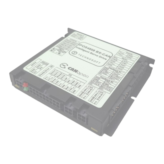
- Page 1 BX-CAN / BX-CAN-STO Intelligent Servo Drive for Step, DC, Brushless Intelligent Servo Drives DC and AC Motors Technical Reference © Technosoft 2023 P091.027.iPOS4808.BX.CAN.CAN-STO.UM.0523...
-
Page 2: Table Of Contents
Single loop configurations ...................... 12 ..2.4.2 Dual loop configurations ......................12 ..Hardware Installation ..................... 13 iPOS4808 BX-CAN / -STO Board Dimensions ............13 Mechanical Mounting ....................14 Connectors and Pinouts .................... 15 3.3.1 Pinouts for iPOS4808 BX-CAN-STO ..................15 .. - Page 3 3.4.7.11 Recommendations for wiring ..................29 3.4.8 Power Supply ......................... 30 ..3.4.8.1 Supply Connection and STO connection for iPOS4808 BX-CAN-STO ......30 3.4.8.2 Supply Connection for iPOS4808 BX-CAN ..............31 3.4.8.3 Recommendations for Supply Wiring ................31 3.4.8.4 Recommendations to limit over-voltage during energy regeneration ......31 3.4.9...
-
Page 4: Read This First
Whilst Technosoft believes that the information and guidance given in this manual is correct, all parties must rely upon their own skill and judgment when making use of it. Technosoft does not assume any liability to anyone for any loss or damage caused by any error or omission in the work, whether such error or omission is the result of negligence or any other cause. -
Page 5: Related Documentation
SI units and the drive internal units. Help of the EasySetUp software – describes how to use EasySetUp to quickly setup any Technosoft drive for your application using only 2 dialogues. The output of EasySetUp is a set of setup data that can be downloaded into the drive EEPROM or saved on a PC file. -
Page 6: Safety Information
To prevent electrostatic damage, avoid contact with insulating materials, such as synthetic fabrics or plastic surfaces. In order to discharge static electricity build-up, place the drive on a grounded conductive surface and also ground yourself. © Technosoft 2023 iPOS4808 BX-CAN / -STO Technical Reference... -
Page 7: Quality System, Conformance And Certifications
1907/2006 (Registration, Evaluation, Authorization and Restriction of Chemicals), which came into force on 01.06.2007. RoHS Compliance - Technosoft SA here with declares that this product is manufactured in compliance with the RoHS directive 2002/95/EC on the restriction of the use of certain hazardous substances in electrical and electronic equipment... -
Page 8: Product Overview
Using the high-level Technosoft Motion Language (TML) the following operations can be executed directly at drive level: ❑ Setting various motion modes (profiles, PVT, PT, electronic gearing or camming , etc.) - Page 9 Hence neither the iPOS4808 TML programming capability nor the drive camming mode are used. EasySetUp can be downloaded free of charge from Technosoft web page. EasyMotion Studio platform includes EasySetUp for the drive setup, and a Motion Wizard for the motion programming.
-
Page 10: Product Features
Various modes of operation, including: cyclic synchronous position; torque, speed or position control; position or speed profiles, external analogue reference or sent via a communication bus • Technosoft Motion Language (TML) instruction set for the definition and execution of motion sequences • Standalone operation with stored motion sequences •... -
Page 11: Identification Labels
The iPOS4808 BX can have the following part numbers and names on the identification label: p.n. P027.314.E201 name iPOS4808 BX-CAN-STO – standard CAN execution with STO p.n. P027.314.E701 name iPOS4808 BX-CAN-STO – Linear Hall CAN execution with STO p.n. P027.214.E201 name iPOS4808 BX-CAN- – standard CAN execution without STO 8A cont. -
Page 12: Supported Motor-Sensor Configurations
#1) on load. A differential encoder on Feedback #1 is available only with P027.314.E201 and P027.214.E201 Linear hall sensors are compatible only with P027.314.E701 Available starting with firmware version F514K © Technosoft 2023 iPOS4808 BX-CAN / -STO Technical Reference... -
Page 13: Hardware Installation
Hardware Installation iPOS4808 BX-CAN / -STO Board Dimensions Figure 3.1.1. iPOS4808 BX-CAN / -STO drive dimensions All dimensions are in mm. The drawings are not to scale. © Technosoft 2023 iPOS4808 BX-CAN / -STO Technical Reference... -
Page 14: Mechanical Mounting
Figure 3.2.1. iPOS4808 BXO dimensions with mating connectors The iPOS4808 BX-CAN drive(s) can be cooled by natural convection. The support shall be thermally conductive (metallic), and can be mounted vertically or horizontally. Figure 3.2.2. Recommended spacing go vertical and horizontal mounting, worst case: non-metallic, closed box The figures above shows the minimum spacing to assure proper airflow by natural convection. -
Page 15: Connectors And Pinouts
With proper ventilation, keeping the air surrounding the iPOS4808 BX inside the limits indicated, the spacing values may be reduced down to zero. Connectors and Pinouts 3.3.1 Pinouts for iPOS4808 BX-CAN-STO © Technosoft 2023 iPOS4808 BX-CAN / -STO Technical Reference... -
Page 16: Pinouts For Ipos4808 Bx-Can
3.3.2 Pinouts for iPOS4808 BX-CAN © Technosoft 2023 iPOS4808 BX-CAN / -STO Technical Reference... -
Page 17: Mating Connectors
J3, J4 MOLEX 79758-2023 Female, Tin (Sn) Plating, 300.00mm Length, 22 AWG J5, J6, J7, J8, Pre-Crimped Lead Micro-Fit 3.0 Female-to-Micro-Fit 3.0 MOLEX 79758-0010 Female, Tin (Sn) Plating, 300.00mm Length, 20 AWG © Technosoft 2023 iPOS4808 BX-CAN / -STO Technical Reference... -
Page 18: Connection Diagrams
Connection diagrams 3.4.1 iPOS4808 BX-CAN-STO connection diagram Figure 3.3. iPOS4808 BX-CAN-STO Connection diagram * For other available feedback / motor options, check the detailed connection diagrams below © Technosoft 2023 iPOS4808 BX-CAN / -STO Technical Reference... -
Page 19: Ipos4808 Bx-Can Connection Diagram
3.4.2 iPOS4808 BX-CAN connection diagram Figure 3.4. iPOS4808 BX-CAN Connection diagram * For other available feedback / motor options, check the detailed connection diagrams below © Technosoft 2023 iPOS4808 BX-CAN / -STO Technical Reference... -
Page 20: 24V Digital I/O Connection
The inputs are compatible with NPN type outputs (input must be pulled to GND to change its default state) The length of the cables must be up to 30m, reducing the exposure to voltage surges in industrial environment. © Technosoft 2023 iPOS4808 BX-CAN / -STO Technical Reference... -
Page 21: Npn Outputs
The length of the cables must be up to 30m, reducing the exposure to voltage surges in industrial environment. The output loads can be individually and independently connected to +5V or to GND. © Technosoft 2023 iPOS4808 BX-CAN / -STO Technical Reference... -
Page 22: Analog Inputs Connection
(GND); shield is connected only at the drive side, to the drive GND, and is left unconnected at the source side. The source minus (negative, out-of-phase) output remains unconnected. © Technosoft 2023 iPOS4808 BX-CAN / -STO Technical Reference... -
Page 23: Motor Connections
Brushless Motor connection Figure 3.11. Brushless motor connection 3.4.6.2 2-phase Step Motor connection Figure 3.12. 2-phase step motor connection, one coil per phase Figure 3.13. 2-phase step motor connection, two coils per phase © Technosoft 2023 iPOS4808 BX-CAN / -STO Technical Reference... -
Page 24: 3-Phase Step Motor Connection
The inductors must be magnetically shielded (toroidal, for example), and must be rated for the motor surge current. Typically the necessary values are around 100 μH. A good shielding can be obtained if the motor wires are running inside a metallic cable guide. © Technosoft 2023 iPOS4808 BX-CAN / -STO Technical Reference... -
Page 25: Feedback Connections
Differential Incremental Encoder #1 Connection Figure 3.17. Differential incremental encoder #1 connection Remark: The length of the cables must be up to 30m, reducing the exposure to voltage surges in industrial environment. © Technosoft 2023 iPOS4808 BX-CAN / -STO Technical Reference... -
Page 26: Pulse&Direction Encoder #1 Connection
The encoder #2 input has internal terminators, equivalent to 120Ω (0.25W) , present in the drive. The length of the cables must be up to 30m, reducing the exposure to voltage surges in industrial environment. © Technosoft 2023 iPOS4808 BX-CAN / -STO Technical Reference... -
Page 27: Ssi / Endat Encoder #2 Connection
The encoder #2 input has internal terminators, equivalent to 120Ω (0.25W) , present in the drive. The length of the cables must be up to 30m, reducing the exposure to voltage surges in industrial environment. EnDAT2.2 protocol is available starting with F514K firmware version © Technosoft 2023 iPOS4808 BX-CAN / -STO Technical Reference... -
Page 28: Digital Hall Connection For Motor + Hall + Incremental Encoder
This connection is required when using only Digital hall signals as the main feedback device for motor control. In this case, no incremental encoder is needed. The length of the cables must be up to 30m, reducing the exposure to voltage surges in industrial environment. © Technosoft 2023 iPOS4808 BX-CAN / -STO Technical Reference... -
Page 29: Sine-Cosine Analog Encoder Connection
1 meter. Connect the cable shield to the GND, at only one end. This point A linear hall connection is possible only with the drive Product ID: P027.314.E701 © Technosoft 2023 iPOS4808 BX-CAN / -STO Technical Reference... -
Page 30: Power Supply
Power Supply 3.4.8.1 Supply Connection and STO connection for iPOS4808 BX-CAN-STO Figure 3.26. Supply connection * The STO and +Vlog inputs can be supplied from the same power source as long as its output voltage is 18 to 36V DC from a SELV/ PELV power supply. -
Page 31: Supply Connection For Ipos4808 Bx-Can
The capacitor must be rated to a voltage equal or bigger than the maximum expected over-voltage and can be sized with the formula: − where: = 53V is the over-voltage protection limit is the nominal motor supply voltage © Technosoft 2023 iPOS4808 BX-CAN / -STO Technical Reference... - Page 32 − − CHOP where C is the capacitance on the motor supply (external), i.e: CHOP to limit the average current below the drive nominal current I =0.9A © Technosoft 2023 iPOS4808 BX-CAN / -STO Technical Reference...
-
Page 33: Serial Rs-232 Connection
Do not rely on an earthed PC to provide the iPOS4808 GND connection! The drive must be earthed through a separate circuit. Most communication problems are caused by the lack of such connection © Technosoft 2023 iPOS4808 BX-CAN / -STO Technical Reference... -
Page 34: 3.4.10 Can-Bus Connection
105 ... 135 ohms (120 ohms typical) and a capacitance below 30pF/meter. The 120 termination resistors must be rated at 0.2W minimum. Do not use winded resistors, which are inductive. Figure 3.29. Multiple-Axis CAN network © Technosoft 2023 iPOS4808 BX-CAN / -STO Technical Reference... -
Page 35: 3.4.11 Disabling Autorun
CAN Operation Mode and Axis ID Selection 3.5.1 Selection of the Operation Mode On iPOS4808 BX-CAN, the selection of the operation mode CANopen or TMLCAN is done by setting the SW2 position 6 switch: • CANopen mode, SW2 pin6 = ON (down position) •... -
Page 36: Selection Of The Axis Id
Lit after power-on when the drive initialization ends. Turned off when an error occurs. Drive Error Turned on when the drive detects an error condition or when OUT2/Error is set to +Vlog with OUT(2)=0 TML instruction. © Technosoft 2023 iPOS4808 BX-CAN / -STO Technical Reference... -
Page 37: Electrical Specifications
In case of forced cooling (conduction or ventilation) the spacing requirements may drop down to mechanical tolerances as long as the ambient temperature is kept below the maximum operating limit © Technosoft 2023 iPOS4808 BX-CAN / -STO Technical Reference... -
Page 38: Motor Outputs (A/A+, B/A-, C/B+, Cr/B-)
Logic “HIGH”, leakage current; external load to +V max = 40V Minimum pulse width µs ESD protection - Human body model ±15 The digital inputs are software selectable as PNP or NPN © Technosoft 2023 iPOS4808 BX-CAN / -STO Technical Reference... -
Page 39: Digital Hall Inputs (Hall1, Hall2, Hall3)
For many applications, a termination resistor should be connected across SIN+ to SIN-, and across COS+ to COS-. This can be achieved by setting SW2 pins 3,4 and 5 to ON. Please consult the feedback device datasheet for confirmation. © Technosoft 2023 iPOS4808 BX-CAN / -STO Technical Reference... -
Page 40: 3.6.15 Can-Bus
Software selectable Counting direction DATA resolution Total resolution (single turn or single turn + multi turn) Protocol BiSS C mode (sensor mode) EnDAT 2.2 protocol available starting with F514K firmware version © Technosoft 2023 iPOS4808 BX-CAN / -STO Technical Reference... -
Page 41: Analog 0
† Stresses beyond values listed under “absolute maximum ratings” may cause permanent damage to the device. Exposure to absolute-maximum-rated conditions for extended periods may affect device reliability. “FS” stands for “Full Scale” STO inputs are available only for iPOS4808 BX-CAN-STO ENABLE inputs are available only for iPOS4808 BX-CAN © Technosoft 2023... -
Page 42: 3.6.23 Ipos4808 Bx-Can / -Sto Derating Curves
Figure 4. iPOS4808 BX De-rating with altitude Memory Map iPOS4808 BX-CAN has 2 types of memory available for user applications: 16K16 SRAM and up to 16K16 serial ROM. The SRAM memory is mapped in the address range: C000h to FFFFh. It can be used to download and run a TML program, to save real-time data acquisitions and to keep the cam tables during run-time. - Page 43 © Technosoft 2023 iPOS4808 BX-CAN / -STO Technical Reference...
Need help?
Do you have a question about the iPOS4808 BX-CAN and is the answer not in the manual?
Questions and answers