
Related Manuals for Technosoft iPOS4808 MYCAT-STO


Summarization of Contents
Safety Information and Precautions
1.1 Warnings
Signals danger to the operator, possibly causing bodily injury. Includes prevention instructions.
1.2 Cautions
Signals danger to equipment or product, possibly causing damage. Includes avoidance instructions.
1.3 Quality System, Conformance, and Certifications
Details certifications and compliance with quality standards like ISO 9001, REACH, and RoHS.
Product Overview and Features
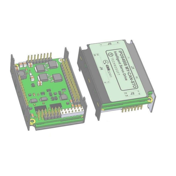
2.1 Introduction
Provides an overview of the iPOS4808 as a digital intelligent servo drive with embedded motion controller.
2.2 Product Features
Lists key features such as motor compatibility, compact design, control modes, and TML instruction set.
2.3 Identification Labels
Explains the identification labels on the iPOS4808 MY series drives and their part numbers.
2.4 Supported Motor-Sensor Configurations
Details supported motor types and feedback sensor configurations for single and dual loop setups.
2.4.1 Single Loop Configurations
Describes single feedback sensor usage and the role of the second sensor input.
2.4.2 Dual Loop Configurations
Explains dual loop configurations where speed and position control use different feedback sensors.
2.5 iPOS4808 MY I/O Evaluation Board
Describes the availability of a circuit board for evaluating iPOS4808 drive types and ordering information.
Hardware Installation Guide
3.1 iPOS4808 MY-CAN-STO Board Dimensions
Provides detailed physical dimensions and mounting information for the iPOS4808 MY-CAN-STO drive.
3.2 iPOS4808 MY-CAT-STO Board Dimensions
Provides detailed physical dimensions and mounting information for the iPOS4808 MY-CAT-STO drive.
3.3 Mechanical Mounting
Details recommendations for horizontal mounting on a motherboard and thermal considerations.
3.3.1 iPOS4808 MY-CAN-STO PCB Footprint
Shows the PCB footprint layout for the iPOS4808 MY-CAN-STO drive for motherboard design.
3.3.2 iPOS4808 MY-CAT-STO PCB Footprint
Shows the PCB footprint layout for the iPOS4808 MY-CAT-STO drive for motherboard design.
3.4 Motherboard PCB Design
Offers recommendations for designing the motherboard PCB for optimal iPOS4808 integration and EMI performance.
3.5 Connectors and Pinouts
Lists pinouts for the iPOS4808 MY-CAN-STO and mating connector details for CAN and CAT.
3.5.1 Pinouts for iPOS4808 MY-CAN-STO
Detailed pin assignments for the iPOS4808 MY-CAN-STO drive connectors J1, J2, J4, J5.
3.5.2 Mating Connectors for CAN and CAT
Specifies manufacturers and part numbers for mating connectors used with CAN and CAT drives.
3.5.3 Pinouts for iPOS4808 MY-CAT-STO
Detailed pin assignments for the iPOS4808 MY-CAT-STO drive connectors J1, J2, J4, J5, J33.
3.6 Connection Diagrams
Illustrates various connection diagrams for the iPOS4808 drives.
3.6.1 iPOS4808 MY-CAN-STO Connection Diagram
Provides a detailed connection diagram for the iPOS4808 MY-CAN-STO drive, showing all interfaces.
3.6.2 iPOS4808 MY-CAT-STO Connection Diagram
Provides a detailed connection diagram for the iPOS4808 MY-CAT-STO drive, showing all interfaces.
3.6.3 24V Digital I/O Connection
Explains how to connect 24V digital inputs (PNP/NPN) and outputs for the iPOS4808 drives.
3.6.3.1 PNP Inputs
Details the connection scheme for 24V PNP digital inputs to the iPOS4808.
3.6.3.2 NPN Inputs
Details the connection scheme for 24V NPN digital inputs to the iPOS4808.
3.6.3.3 NPN Outputs
Details the connection scheme for 24V NPN digital outputs from the iPOS4808.
3.6.4 5V Digital I/O Connection
Illustrates the connection of 5V digital I/O for the iPOS4808 drives, including input and output configurations.
3.6.5 Analog Inputs Connection
Explains the wiring for analog inputs, covering 0-5V range and +/-10V to 0-5V adapters.
3.6.5.1 0-5V Input Range
Shows the connection diagram for analog inputs with a 0-5V input range.
3.6.5.2 +/- 10V to 0-5V Input Range Adapter
Details the adapter circuit for converting +/-10V signals to a 0-5V range for analog inputs.
3.6.5.3 Recommendation for Wiring
Provides wiring recommendations for analog signal sources, including single-ended and differential types.
3.6.6 Motor Connections
Details how to connect different types of motors (Brushless, Step, DC) to the iPOS4808 drives.
3.6.6.1 Brushless Motor Connection
Illustrates the connection diagram for brushless motors to the iPOS4808.
3.6.6.2 2-Phase Step Motor Connection
Shows connection diagrams for 2-phase stepper motors in series and parallel configurations.
3.6.6.3 3-Phase Step Motor Connection
Provides the connection diagram for 3-phase stepper motors to the iPOS4808.
3.6.6.4 DC Motor Connection
Illustrates the connection diagram for DC motors to the iPOS4808.
3.6.6.5 Recommendations for Motor Wiring
Offers advice on motor wiring practices, including cable routing, shielding, and series inductors.
3.6.7 Feedback Connections
Explains how to connect various feedback devices like encoders and Hall sensors.
3.6.7.1 Single-ended Incremental Encoder #1 Connection
Details the wiring for a single-ended incremental encoder connected to the first feedback input.
3.6.7.2 Differential Incremental Encoder #1 Connection
Shows the wiring for a differential incremental encoder on the first feedback input, including terminators.
3.6.7.3 Differential Incremental Encoder #2 Connection
Details the connection of a differential incremental encoder to the second feedback input.
3.6.7.4 Sine-Cosine Analog Encoder Connection
Illustrates the connection for sine-cosine analog encoders to the iPOS4808.
3.6.7.5 SSI Encoder #2 Connection
Provides the connection diagram for an SSI encoder to the second feedback input.
3.6.7.6 BiSS Encoder #2 Connection
Shows the connection diagram for a BiSS-C encoder to the second feedback input.
3.6.7.7 Digital Hall Connection for Motor + Hall + Incremental Encoder
Explains Hall sensor connections when used with incremental encoders for BLDC/PMSM motors.
3.6.7.8 Digital Hall Connection for Direct Motor Control without Encoder
Details Hall sensor connections for direct motor control when no encoder is used.
3.6.7.9 Linear Hall Connection
Illustrates the connection of linear Hall sensors for position feedback.
3.6.7.10 Recommendations for Wiring
Offers wiring advice for feedback sensors, emphasizing shielded cables and proper grounding.
3.6.8 Power Supply and STO Connection
Covers power supply connections and the Safe Torque Off (STO) functionality.
3.6.8.1 Supply Connection
Shows the main power supply connections for the iPOS4808, including logic and motor supplies.
3.6.8.2 Recommendations for Supply Wiring
Provides guidelines for wiring power supply lines, including capacitor placement and wire gauge.
3.6.8.3 Recommendations to Limit Over-Voltage During Braking
Explains how to manage regenerative energy during braking to prevent over-voltage issues.
3.6.9 Serial RS-232 Connection
Details the serial RS-232 connection for communication and configuration.
3.6.9.1 Serial RS-232 Connection
Illustrates the physical connection for the RS-232 serial interface.
3.6.9.2 Recommendation for Wiring
Offers recommendations for building and connecting serial cables for reliable RS-232 communication.
3.6.10 CAN-Bus Connection (for CAN Drives Only)
Explains how to connect CAN drives using the CAN-bus protocol.
3.6.10.1 CAN Connection
Shows the basic CAN connection diagram, including network termination requirements.
3.6.10.2 Recommendation for Wiring
Provides wiring guidelines for CAN networks, including cable types, PCB layout, and daisy-chaining.
3.6.11 EtherCAT Bus Connection (for CAT Drives)
Details the EtherCAT bus connection for CAT drives, including RJ45 and M8 connectors.
3.6.12 Removal from Autorun Mode
Explains methods to remove the drive from the automatic Autorun mode upon power-up.
3.7 CAN Operation Mode and Axis ID Selection for CAN Drives (J1 Pin Settings)
Describes how to set CAN operation mode (CANopen/TMLCAN) and Axis ID using J1 pin settings.
3.8 Axis ID Selection for CAT Drives (J1 Pin Settings)
Explains how to set the Axis ID for CAT drives using J1 pin settings for EtherCAT addressing.
3.9 Electrical Specifications
Lists electrical parameters and operating conditions for the iPOS4808 drives.
3.9.1 Operating Conditions
Lists the operating conditions including ambient temperature, humidity, and altitude.
3.9.2 Storage Conditions
Specifies the storage conditions for the iPOS4808 drives, including temperature and humidity.
3.9.3 Mechanical Mounting
Provides specifications related to mechanical mounting, such as airflow and spacing requirements.
3.9.4 Environmental Characteristics
Details environmental characteristics like drive dimensions, weight, cleaning agents, and protection degree.
3.9.5 Logic Supply Input (+VLOG)
Specifies the voltage and current ratings for the logic supply input (+VLOG).
3.9.6 Motor Supply Input (+VMOT)
Details the voltage and current ratings for the motor supply input (+VMOT).
3.9.7 Motor Outputs (A/A+, B/A-, C/B+, BR/B-)
Lists specifications for motor outputs, including nominal current, peak current, and short-circuit protection.
3.9.8 Digital Inputs (INO, IN1, IN2/LSP, IN3/LSN, IN4, IN5)
Provides specifications for digital inputs, including mode compliance, voltage, and current.
3.9.9 Digital Outputs (OUT0, OUT1, OUT2/Error, OUT3/ Ready, OUT4)
Specifies details for digital outputs, covering mode compliance, voltage, current, and pulse width.
3.9.10 Digital Hall Inputs (Hall1, Hall2, Hall3)
Lists specifications for digital Hall inputs, including voltage, current, and pulse width.
3.9.11 Encoder #1 Inputs (A1+, A1-, B1+, B1-, Z1+, Z1-,)
Details specifications for Encoder #1 inputs, including single-ended and differential modes.
3.9.12 Encoder #2 Inputs (A2+, A2-, B2+, B2-, Z2+, Z2-)
Specifies details for Encoder #2 inputs, including differential mode and impedance.
3.9.13 Linear Hall Inputs (LH1, LH2, LH3)
Lists specifications for linear Hall inputs, including voltage range and current.
3.9.14 Sin-Cos Encoder Inputs (Sin+, Sin-, Cos+, Cos-)
Details specifications for Sin-Cos encoder inputs, including voltage and impedance.
3.9.15 SSI Encoder Interface
Specifies characteristics of the SSI encoder interface, including clock output and data impedance.
3.9.16 BiSS Encoder Interface
Details specifications for the BiSS Encoder Interface, including clock output and data impedance.
3.9.17 Analog 0...5V Inputs (REF, FDBK)
Lists specifications for analog inputs, including voltage range, impedance, and resolution.
3.9.18 RS-232
Specifies compliance standards, protection, and ESD for the RS-232 interface.
3.9.19 CAN-Bus (for CAN Drives)
Details CAN-Bus specifications, including compliance, bit rate, resistor, and addressing modes.
3.9.20 Supply Output (+5V)
Specifies the voltage and current ratings for the +5V supply output.
3.9.21 Ethernet Ports (for CAT Drives)
Details Ethernet port specifications for CAT drives, including compliance and Power over Ethernet.
3.9.22 LED Signals (for J33 of CAT Drives)
Describes the LED connections and specifications for the CAT drives.
3.9.23 Safe Torque OFF (STO1+; STO1-; STO2+; STO2-)
Provides safety classification, performance, and input specifications for the Safe Torque Off function.
Memory Map Details
4 Memory Map
Explains the available memory types (SRAM, E2ROM) and their address ranges for TML programs and data.
Need help?
Do you have a question about the iPOS4808 MYCAT-STO and is the answer not in the manual?
Questions and answers