Sign In
Upload
Manuals
Brands
Technosoft Manuals
Servo Drives
iPOS4808 BX-CAN
Technosoft iPOS4808 BX-CAN Manuals
Manuals and User Guides for Technosoft iPOS4808 BX-CAN. We have
2
Technosoft iPOS4808 BX-CAN manuals available for free PDF download: Technical Reference
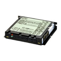
Technosoft iPOS4808 BX-CAN Technical Reference (107 pages)
Intelligent Servo Drive for Step, DC, Brushless DC and AC Motors
Brand:
Technosoft
| Category:
Servo Drives
| Size: 3.5 MB
Table of Contents
Table of Contents
9
Safety Information
15
Warnings
15
Cautions
16
Product Overview
17
Introduction
17
Key Features
19
Identifying the Drive Hardware Revision
21
Supported Motor-Sensor Configurations
22
Single Ended Configurations
22
Dual Loop Configurations
22
Ipos4808 BX-CAN Drive Dimensions
23
Identification Labels
23
Electrical Specifications
24
Operating Conditions
24
Storage Conditions
24
Mechanical Mounting
24
Environmental Characteristics
24
Logic Supply Input
25
Log )
25
Motor Supply Input
25
Mot )
25
Motor Outputs (A/A+, B/A-, C/B+, BR/B-)
25
Digital Inputs (IN0, IN1, IN2/LSP, IN3/LSN, IN5, IN6)
27
Digital Outputs (OUT0, OUT1, Out2/Error, OUT3/ Ready, OUT4)
28
Digital Hall Inputs (Hall1, Hall2, Hall3)
28
Encoder1 Inputs (A1/A1+, A1-, B1/B1+, B1-, Z1/Z1+, Z1-)
29
Encoder2 Inputs (A2+/Data+, A2-/Data-, B2+/Clk+, B2-/Clk-, Z2+, Z2-)
30
Linear Hall Inputs (LH1, LH2, LH3)
30
Sin-Cos Encoder Inputs (Sin+, Sin-, Cos+, Cos-)
30
Analog 0
31
CAN-Bus
32
Supply Output (+5V)
32
Step 1. Hardware Installation
33
Mechanical Mounting
33
Vertical Mounting
33
Horizontal Mounting
35
Mating Connectors
36
Connectors and Connection Diagrams
37
Connector Layout
37
J1 Motor and Logic Supply Input Connector Pinout
37
J2 Motor Output and Digital Hall Signals Connector Pinout
38
J3 Primary Feedback Connector Pinout for the P.n. P027.214.E201
38
J3 Primary Feedback Connector Pinout for the P.n. P027.214.E701
38
J4 Secondary Feedback Connector Pinout
39
J5, J6 CAN Connectors Pinout
39
J7 Digital, Analog I/O and Logic Supply Connector Pinout
39
J8 RS232 Connector Pinout
40
J9 Enable Circuit Connector Pinout
40
SW1 Axis ID Selection Switches
40
SW2 Hardware Configuration Selection DIP Switch
40
Digital I/O Connection
41
Analog Inputs Connection
43
Motor Connections
45
Feedback Connections
48
Power Supply Connection
56
Serial RS-232 Connection
59
CAN-Bus Connection
60
Disabling Autorun Mode
62
Operation Mode and Axis ID Selection
63
Selection of the Operation Mode
63
Selection of the Axis ID
63
Step 2. Drive Setup
64
Installing Easysetup
64
Getting Started with Easysetup
64
Establish Communication
65
Setup Drive/Motor
66
Selecting NPN/PNP Inputs Type in Setup
68
Selecting the Feedback Source for Pulse and Direction
68
Download Setup Data to Drive/Motor
69
Evaluate Drive/Motor Behavior (Optional)
69
Changing the Drive Axis ID
70
Setting Canbus Rate
72
Creating an Image File with the Setup Data
73
Step 3. Motion Programming
74
Using a Canopen Master (for Ipos4808 Canopen Execution)
74
Cia-301 Application Layer and Communication Profile Overview
74
Cia-305 Layer Setting Services (LSS) and Protocols Overview
75
Cia-402 and Manufacturer Specific Device Profile Overview
75
Technocan Extension
75
Checking Setup Data Consistency
75
Using the Built-In Motion Controller and TML
76
Technosoft Motion Language Overview
76
Installing Easymotion Studio
76
Getting Started with Easymotion Studio
77
Creating an Image File with the Setup Data and the TML Program
83
Combining Canopen /Or Other Host with TML
83
Using TML Functions to Split Motion between Master and Drives
84
Executing TML Programs
84
Loading Automatically Cam Tables Defined in Easymotion Studio
84
Customizing the Homing Procedures
84
Customizing the Drive Reaction to Fault Conditions
85
Using Motion Libraries for PC-Based Systems
85
Using Motion Libraries for PLC-Based Systems
86
Scaling Factors
87
Position Units
87
Brushless / DC Brushed Motor with Quadrature Encoder on Motor
87
Brushless Motor with Linear Hall Signals
87
DC Brushed Motor with Quadrature Encoder on Load and Tacho on Motor
88
Step Motor Open-Loop Control. no Feedback Device
88
Step Motor Open-Loop Control. Incremental Encoder on Load
88
Brushless Motor with Sine/Cosine Encoder on Motor
89
Speed Units
89
Brushless / DC Brushed Motor with Quadrature Encoder on Motor
89
Brushless Motor with Linear Hall Signals
90
DC Brushed Motor with Quadrature Encoder on Load and Tacho on Motor
90
DC Brushed Motor with Tacho on Motor
90
Step Motor Open-Loop Control. no Feedback Device
91
Step Motor Closed-Loop Control. Incremental Encoder on Motor
91
Brushless Motor with Sine/Cosine Encoder on Motor
92
Acceleration Units
92
Brushless / DC Brushed Motor with Quadrature Encoder on Motor
92
Brushless Motor with Linear Hall Signals
93
DC Brushed Motor with Quadrature Encoder on Load and Tacho on Motor
93
Step Motor Open-Loop Control. no Feedback Device
94
Step Motor Open-Loop Control. Incremental Encoder on Load
94
Step Motor Closed-Loop Control. Incremental Encoder on Motor
94
Brushless Motor with Sine/Cosine Encoder on Motor
95
Jerk Units
96
Brushless / DC Brushed Motor with Quadrature Encoder on Motor
96
Brushless Motor with Linear Hall Signals
96
DC Brushed Motor with Quadrature Encoder on Load and Tacho on Motor
97
Step Motor Open-Loop Control. no Feedback Device
97
Step Motor Open-Loop Control. Incremental Encoder on Load
97
Step Motor Closed-Loop Control. Incremental Encoder on Motor
98
Brushless Motor with Sine/Cosine Encoder on Motor
98
Current Units
98
Voltage Command Units
99
Voltage Measurement Units
99
Time Units
99
Master Position Units
100
Master Speed Units
100
Motor Position Units
100
Brushless / DC Brushed Motor with Quadrature Encoder on Motor
100
Brushless Motor with Linear Hall Signals
100
DC Brushed Motor with Quadrature Encoder on Load and Tacho on Motor
100
Step Motor Open-Loop Control. no Feedback Device
101
Step Motor Open-Loop Control. Incremental Encoder on Load
101
Step Motor Closed-Loop Control. Incremental Encoder on Motor
101
Brushless Motor with Sine/Cosine Encoder on Motor
101
Motor Speed Units
102
Brushless / DC Brushed Motor with Quadrature Encoder on Motor
102
Brushless Motor with Linear Hall Signals
102
DC Brushed Motor with Quadrature Encoder on Load and Tacho on Motor
102
DC Brushed Motor with Tacho on Motor
103
Step Motor Open-Loop Control. no Feedback Device or Incremental Encoder
103
On Load
103
Step Motor Closed-Loop Control. Incremental Encoder on Motor
103
Brushless Motor with Sine/Cosine Encoder on Motor
104
Memory Map
105
Advertisement
Technosoft iPOS4808 BX-CAN Technical Reference (43 pages)
Intelligent Servo Drives
Brand:
Technosoft
| Category:
Servo Drives
| Size: 6.14 MB
Table of Contents
Table of Contents
2
Read this First
4
About this Manual
4
Notational Conventions
4
Related Documentation
5
If You Need Assistance
5
Safety Information
6
Warnings
6
Cautions
6
Quality System, Conformance and Certifications
7
Product Overview
8
Introduction
8
Product Features
10
Identification Labels
11
Supported Motor-Sensor Configurations
12
Single Loop Configurations
12
Dual Loop Configurations
12
Hardware Installation
13
Ipos4808 BX-CAN / -STO Board Dimensions
13
Mechanical Mounting
14
Connectors and Pinouts
15
Pinouts for Ipos4808 BX-CAN-STO
15
Pinouts for Ipos4808 BX-CAN
16
Mating Connectors
17
Connection Diagrams
18
Ipos4808 BX-CAN-STO Connection Diagram
18
Ipos4808 BX-CAN Connection Diagram
19
24V Digital I/O Connection
20
PNP Inputs
20
NPN Inputs
20
NPN Outputs
21
5V Digital I/O Connection
21
Analog Inputs Connection
22
0-5V Input Range
22
10V to 0-5V Input Range Adapter
22
Recommendation for Wiring
22
Motor Connections
23
Brushless Motor Connection
23
2-Phase Step Motor Connection
23
3-Phase Step Motor Connection
24
DC Motor Connection
24
Recommendations for Motor Wiring
24
Feedback Connections
25
Single-Ended Incremental Encoder #1 Connection
25
Differential Incremental Encoder #1 Connection
25
Pulse&Direction Encoder #1 Connection
26
Differential Incremental Encoder #2 Connection
26
SSI / Endat Encoder #2 Connection
27
Biss Encoder #2 Connection
27
Digital Hall Connection for Motor + Hall + Incremental Encoder
28
Digital Hall Connection for Direct Motor Control Without an Encoder
28
Sine-Cosine Analog Encoder Connection
29
Linear Hall Connection
29
Recommendations for Wiring
29
Power Supply
30
Supply Connection and STO Connection for Ipos4808 BX-CAN-STO
30
Supply Connection for Ipos4808 BX-CAN
31
Recommendations for Supply Wiring
31
Recommendations to Limit Over-Voltage During Energy Regeneration
31
Serial RS-232 Connection
33
Recommendation for Wiring
33
3.4.10 CAN-Bus Connection
34
CAN Connection
34
Recommendation for Wiring
34
3.4.11 Disabling Autorun
35
CAN Operation Mode and Axis ID Selection
35
Selection of the Operation Mode
35
Selection of the Axis ID
36
LED Indicators
36
Electrical Specifications
37
Operating Conditions
37
Storage Conditions
37
Mechanical Mounting
37
Environmental Characteristics
37
Logic Supply Input
37
Log )
37
Motor Supply Input
37
Mot )
37
Motor Outputs (A/A+, B/A-, C/B+, CR/B-)
38
Digital Inputs (IN0, IN1, IN2/LSP, IN3/LSN, IN5, IN6)
38
Digital Outputs (OUT0, OUT1, Out2/Error, OUT3/ Ready, OUT4)
38
Digital Hall Inputs (Hall1, Hall2, Hall3)
39
Encoder #1 Inputs (A1+, A1-, B1+, B1-, Z1+, Z1-,)
39
Encoder #2 Inputs (A2+, A2-, B2+, B2-, Z2+, Z2-)
39
Linear Hall Inputs (LH1, LH2, LH3)
39
Sin-Cos Encoder Inputs (Sin+, Sin-, Cos+, Cos-)
39
3.6.15 Can-Bus
40
SSI / Endat Encoder Interface
40
3.6.17 Biss Encoder Interface
40
Analog 0
41
Rs-232
41
Safe Torque off (STO1+; STO1-; STO2+; STO2-)
41
Enable Circuit (ENA1, ENA2)
41
3.6.23 Ipos4808 BX-CAN / -STO Derating Curves
42
Memory Map
42
Advertisement
Related Products
Technosoft iPOS4808 MYCAN-STO
Technosoft iPOS4808 MYCAT-STO
Technosoft iPOS4808 VX
Technosoft iPOS4808 MX Series
Technosoft iPOS4808 MX-CAN
Technosoft iPOS4808 MX-CAT
Technosoft iPOS4808 Series
Technosoft iPOS4808 BX-CAN-STO
Technosoft iPOS4808 BX-CAT-STO
Technosoft iPOS4808 MY-CAN
Technosoft Categories
Servo Drives
DC Drives
I/O Systems
Control Unit
Engine
More Technosoft Manuals
Login
Sign In
OR
Sign in with Facebook
Sign in with Google
Upload manual
Upload from disk
Upload from URL