
Related Manuals for Technosoft iPOS4808 BX-CAN


Summary of Contents for Technosoft iPOS4808 BX-CAN
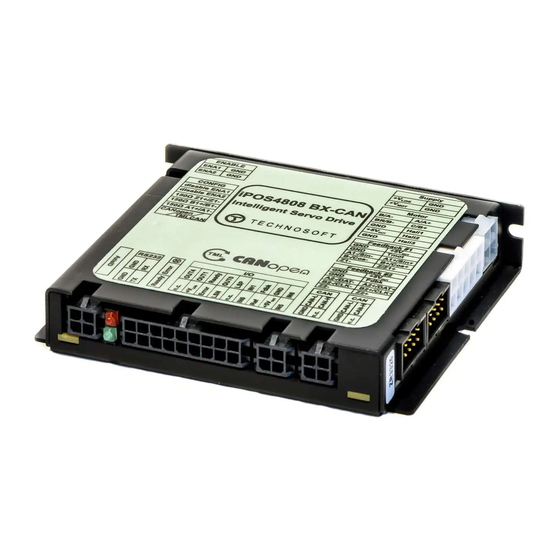
- Page 1 BX-CAN Intelligent Servo Drive Intelligent Servo Drive for Step, DC, Brushless DC and AC Motors Technical Reference Technosoft 2015...
- Page 3 T E C H N O S O F T iPOS4808 BX-CAN Technical Reference P091.027.iPOS4808.BX.UM.0915 Technosoft S.A. Avenue des Alpes 20 CH-2000 NEUCHATEL Switzerland Tel.: +41 (0) 32 732 5500 Fax: +41 (0) 32 732 5504 e-mail: contact@technosoftmotion.com http://www.technosoftmotion.com/...
- Page 5 Whilst Technosoft believes that the information and guidance given in this manual is correct, all parties must rely upon their own skill and judgment when making use of it. Technosoft does not assume any liability to anyone for any loss or damage caused by any error or omission in the work, whether such error or omission is the result of negligence or any other cause.
- Page 6 The Motion Wizard provides a simple, graphical way of creating motion programs and automatically generates all the TML instructions. With EasyMotion Studio you can fully benefit from a key advantage of Technosoft drives – their capability to execute complex motions without requiring an external motion controller, thanks to their built-in motion controller.
- Page 7 Windows or Linux (x86 and x64). TML_LIB_LabVIEW v2.0 (part no. P091.040.LABVIEW.v20.UM.xxxx) – explains how to program in LabVIEW a motion application for the Technosoft intelligent drives using TML_LIB_Labview v2.0 motion control library for PCs. The TML_Lib_LabVIEW includes over 40 ready-to-run examples.
- Page 8 Fax: (41) 32 732 55 04 product operation or report Email: hotline@technosoftmotion.com suspected problems (see Note) Make suggestions about, Mail: Technosoft SA or report errors in documentation (see Note) Avenue des Alpes 20 CH-2000 NEUCHATEL, Switzerland Technosoft 2015 iPOS4808 BX-CAN Technical Reference...
-
Page 9: Table Of Contents
2.4. Supported Motor-Sensor Configurations ..........20 2.4.1. Single ended configurations ............... 20 2.4.2. Dual loop configurations ................20 2.5. iPOS4808 BX-CAN Drive Dimensions ..........21 2.6. Identification Labels ................21 2.7. Electrical Specifications................ 22 2.7.1. Operating Conditions .................. 22 2.7.2. - Page 10 Operation Mode and Axis ID Selection ..........61 3.4.1. Selection of the Operation Mode ..............61 3.4.2. Selection of the Axis ID ................61 Step 2. Drive Setup .................. 62 4.1. Installing EasySetUp ................62 Technosoft 2015 VIII iPOS4808 BX-CAN Technical Reference...
- Page 11 TechnoCAN Extension ................73 5.1.5. Checking Setup Data Consistency ............. 73 5.2. Using the built-in Motion Controller and TML ........74 5.2.1. Technosoft Motion Language Overview ............. 74 5.2.2. Installing EasyMotion Studio ............... 74 5.2.3. Getting Started with EasyMotion Studio ............. 75 5.2.4.
- Page 12 Current units ..................96 6.6. Voltage command units ............... 97 6.7. Voltage measurement units ..............97 6.8. Time units .................... 97 6.9. Master position units ................98 6.10. Master speed units ................98 Technosoft 2015 iPOS4808 BX-CAN Technical Reference...
- Page 13 Step motor open-loop control. No feedback device or incremental encoder on load 6.12.6. Step motor closed-loop control. Incremental encoder on motor .... 101 6.12.7. Brushless motor with sine/cosine encoder on motor......102 Memory Map ................... 103 Technosoft 2015 iPOS4808 BX-CAN Technical Reference...
- Page 14 This page is empty. Technosoft 2015 iPOS4808 BX-CAN Technical Reference...
-
Page 15: Safety Information
INCLUDE INSTRUCTIONS TO AVOID THIS SITUATION 1.1. Warnings TO AVOID ELECTRIC ARCING AND HAZARDS, NEVER WARNING! PLUG / UNPLUG THE iPOS4808 BX-CAN FROM IT’S SOCKET WHILE THE POWER SUPPLIES ARE ON ! THE DRIVE MAY HAVE HOT SURFACES DURING WARNING! OPERATION. -
Page 16: Cautions
1.2. Cautions THE POWER SUPPLIES CONNECTED TO THE DRIVE CAUTION! MUST COMPLY WITH THE PARAMETERS SPECIFIED IN THIS DOCUMENT TROUBLESHOOTING AND SERVICING ARE PERMITTED CAUTION! ONLY FOR PERSONNEL AUTHORISED BY TECHNOSOFT Technosoft 2015 iPOS4808 BX-CAN Technical Reference... -
Page 17: Product Overview
2. Product Overview 2.1. Introduction The iPOS4808 BX-CAN is part of a family of fully digital intelligent servo drives, based on the latest DSP technology and they offer unprecedented drive performance combined with an embedded motion controller. Suitable for control of brushless DC, brushless AC (vector control), DC brushed motors and step motors, the iPOS4808 BX-CAN drives accept as position feedback incremental encoders (quadrature or sine/cosine) and linear Halls signals. - Page 18 TML instructions. With EasyMotion Studio you can fully benefit from a key advantage of Technosoft drives – their capability to execute complex motions without requiring an external motion controller, thanks to their built-in motion controllers.
-
Page 19: Key Features
• Various modes of operation, including: cyclic synchronous position; torque, speed or position control; position or speed profiles, external analogue reference or sent via a communication bus • Technosoft Motion Language (TML) instruction set for the definition and execution of motion sequences • Standalone operation with stored motion sequences •... - Page 20 • CANopen – conforming with CiA 301 v4.2, CiA WD 305 v2.2.13 and CiA DSP 402 v3.0 • TMLCAN – intelligent drive conforming with Technosoft protocol for exchanging TML commands via CAN-bus • 16K × 16 internal SRAM memory for data acquisition •...
-
Page 21: Identifying The Drive Hardware Revision
2.3. Identifying the drive hardware revision shows how to identify the iPOS4808 BX-CAN version. Figure 2.1 This manual refers to iPOS4808 BX-CAN version .10. If your hardware version is .01, please refer to the iPOS4808 BX-CAN Technical Reference Manual with revision 0614 product p/n: P027.014.E201. -
Page 22: Supported Motor-Sensor Configurations
2.4. Supported Motor-Sensor Configurations The iPOS4808 BX-CAN supports the following configurations: 2.4.1. Single ended configurations Motor PMSM BLDC STEP STEP Sensor BRUSH (2-ph) (3-ph) Incr. Encoder Incr. Encoder + Hall Analog Sin/Cos encoder BiSS-C* Linear Halls** Tacho Open-loop (no sensor) *currently in development ** only with the p.n. -
Page 23: Ipos4808 Bx-Can Drive Dimensions
All dimensions are in mm. The drawings are not to scale. 2.6. Identification Labels Figure 2.3. iPOS4808 BX-CAN Identification Labels The iPOS4808 BX-CAN can have the following part numbers on the identification label: p.n. P027.214.E201 – standard execution that supports a single ended and differential incremental encoder of Feedback #1. -
Page 24: Electrical Specifications
(no altitude restriction), but at altitudes over 2,500m, current and power rating are reduced due to thermal dissipation efficiency. In case of forced cooling (conduction or ventilation) the maximum ambient temperature can be increased substantially Technosoft 2015 iPOS4808 BX-CAN Technical Reference... -
Page 25: Logic Supply Input
(sinusoidal amplitude value) for PMSM motors with FOC sinusoidal 5.66 control (sinusoidal effective value) Motor output current, peak maximum 2.5s Short-circuit protection threshold measurement range ±22 ±26 ±30 µs Short-circuit protection delay Technosoft 2015 iPOS4808 BX-CAN Technical Reference... - Page 26 Recommended value, for Motor electrical time-constant ±5% current measurement = 60 kHz µs (L/R) error due to ripple = 80 kHz = 100 kHz Current measurement accuracy FS = Full Scale ±4 ±8 Technosoft 2015 iPOS4808 BX-CAN Technical Reference...
-
Page 27: Digital Inputs (In0, In1, In2/Lsp, In3/Lsn, In5, In6)
Logic “HIGH”; Pulled to +5V 0.15 Logic “HIGH”; Pulled to +24V Input frequency Minimum pulse width µs ESD protection Human body model ±2 The digital inputs are software selectable as PNP or NPN Technosoft 2015 iPOS4808 BX-CAN Technical Reference... -
Page 28: Digital Outputs (Out0, Out1, Out2/Error, Out3/ Ready, Out4)
TTL / CMOS / Open-collector Default state Input floating (wiring disconnected) Logic HIGH Logic “LOW” Logic “HIGH” Input voltage Floating voltage (not connected) Absolute maximum, surge (duration ≤ 1S) † Input current Logic “LOW”; Pull to GND Technosoft 2015 iPOS4808 BX-CAN Technical Reference... -
Page 29: Encoder1 Inputs (A1/A1+, A1-, B1/B1+, B1-, Z1/Z1+, Z1-)
Human body model ±1 For full RS-422 compliance, 150Ω termination resistors must be connected across the differential pairs, set SW2 pins 3, 4 and 5 to ON; not available on the p/n P027.214.E701 Technosoft 2015 iPOS4808 BX-CAN Technical Reference... -
Page 30: Encoder2 Inputs (A2+/Data+, A2-/Data-, B2+/Clk+, B2-/Clk-, Z2+, Z2-)
Interpolation Resolution Depending on software settings bits Frequency Sin-Cos interpolation Encoder2 differential input pins have internal 150Ω termination resistors connected across Available only with the p/n P027.214.E701 Available only with the p/n P027.214.E201 Technosoft 2015 iPOS4808 BX-CAN Technical Reference... -
Page 31: Analog 0
Min. Typ. Max. Units Standards compliance TIA/EIA-232-C Bit rate Depending on software settings 9600 115200 Short-circuit protection 232TX short to GND Guaranteed ESD protection Human body model ±2 “FS” stands for “Full Scale” Technosoft 2015 iPOS4808 BX-CAN Technical Reference... -
Page 32: Can-Bus
ESD protection Human body model ±1 † Stresses beyond values listed under “absolute maximum ratings” may cause permanent damage to the device. Exposure to absolute-maximum-rated conditions for extended periods may affect device reliability. Technosoft 2015 iPOS4808 BX-CAN Technical Reference... -
Page 33: Step 1. Hardware Installation
3. Step 1. Hardware Installation 3.1. Mechanical Mounting The iPOS4808 BX-CAN drive is intended to be mounted vertically or horizontally on a metallic support using the provided mounting holes and the recommended mating connectors, as specified in chapter 3.2. For thermal calculations, each iPOS4808 drive can be assumed to generate 1 Watt at idle, and up to 5 Watts (= 17 BTU/hour) worst case while driving a motor and using all digital outputs. - Page 34 Whenever possible, ventilation openings shall be foreseen on the top side wall or the box and at the bottom of the lateral walls. When using a horizontal support considerably larger than the size of the hosted iPOS4808 BX-CAN drives, it is recommended to provide ventilation holes in the support also.
-
Page 35: Horizontal Mounting
Remark: In case of using a metallic box, with ventilation openings, all spacing values may be reduced substantially. With proper ventilation, keeping the air surrounding the iPOS4808 BX-CAN inside the limits indicated, the spacing values may be reduced down to the mechanical tolerance limits of Figure 3.1. -
Page 36: Mating Connectors
90119-0109 AWG 22..24 MICROFIT RECEPTACLE MOLEX 43025-1800 AWG 20..24 HOUSING, 2x9 WAY MICROFIT RECEPTACLE J5,J6,J8,J9 MOLEX 43025-0400 AWG 20..24 HOUSING, 2x2 WAY J5,J6,J7, CRIMP PIN, MICROFIT, 5A MOLEX 43030-0007 AWG 20..24 J8, J9 Technosoft 2015 iPOS4808 BX-CAN Technical Reference... -
Page 37: Connectors And Connection Diagrams
3.3. Connectors and Connection Diagrams 3.3.1. Connector Layout Figure 3.4. iPOS4808 BX-CAN drive connectors 3.3.2. J1 Motor and logic supply input connector pinout Connector description Name Type Description Negative return (ground) of the power supply Negative return (ground) of the power supply... -
Page 38: J2 Motor Output And Digital Hall Signals Connector Pinout
Linear Hall 1 input Incr. encoder1 A single-ended Return ground for sensors supply Temp Mot NTC/PTC input. Used to read an analog temperature value Return ground for sensors supply 5V output supply for I/O usage Technosoft 2015 iPOS4808 BX-CAN Technical Reference... -
Page 39: J4 Secondary Feedback Connector Pinout
Analogue input, 12-bit, 0-5V. Used to read an analogue position or speed feedback FDBK (as tacho), or used as general purpose analogue input; Connected also to J4 pin 8. 12-36V general-purpose digital PNP/NPN input Technosoft 2015 iPOS4808 BX-CAN Technical Reference... -
Page 40: J8 Rs232 Connector Pinout
Connect an 150Ω resistor between Z1+ and Z1- feedback pins down(ON) Connect an 150Ω resistor between B1+ and B1- feedback pins down(ON) Connect an 150Ω resistor between A1+ and A1- feedback pins down(ON) down(ON) Select CANopen protocol Select TMLCAN protocol down(Off) Technosoft 2015 iPOS4808 BX-CAN Technical Reference... -
Page 41: Digital I/O Connection
Figure 3.6. 24V Digital NPN Inputs connection Remarks: 1. The inputs are selectable as PNP/ NPN by software. 2. The inputs are compatible with NPN type outputs (input must be pulled to GND to change its default state) Technosoft 2015 iPOS4808 BX-CAN Technical Reference... - Page 42 Figure 3.7. 24V Digital NPN Inputs connection Remarks: 1. The outputs are compatible with NPN type inputs (load is tied to common +V , output pulls to GND when active and is floating when inactive) Technosoft 2015 iPOS4808 BX-CAN Technical Reference...
-
Page 43: Analog Inputs Connection
Remark: Default input range for analog inputs is 0÷5 V for REF and FBDK. For a +/-10 V range, see Figure 3.9. 3.3.14.2 +/- 10V to 0-5V Input Range Adapter Figure 3.9. +/-10V to 0-5V adapter Technosoft 2015 iPOS4808 BX-CAN Technical Reference... - Page 44 To further increase the noise protection, use a double shielded cable with inner shield connected to drive GND and outer shield connected to the motor chassis (earth). Technosoft 2015 iPOS4808 BX-CAN Technical Reference...
-
Page 45: Motor Connections
3.3.15. Motor connections 3.3.15.1 Brushless Motor connection Figure 3.10. Brushless motor connection 3.3.15.2 2-phase Step Motor connection Figure 3.11. 2-phase step motor connection, one coil per phase Technosoft 2015 iPOS4808 BX-CAN Technical Reference... - Page 46 Figure 3.12. 2-phase step motor connection, two coils per phase 3.3.15.3 3-Phase Step Motor connection Figure 3.13. 3-phase step motor connection Technosoft 2015 iPOS4808 BX-CAN Technical Reference...
- Page 47 (toroidal, for example), and must be rated for the motor surge current. Typically the necessary values are around 100 μH. c) A good shielding can be obtained if the motor wires are running inside a metallic cable guide. Technosoft 2015 iPOS4808 BX-CAN Technical Reference...
-
Page 48: Feedback Connections
3.3.16. Feedback connections 3.3.16.1 Single-ended Incremental Encoder Feedback #1 Connection Figure 3.15. Single-ended incremental encoder Feedback #1 connection DO NOT CONNECT UNTERMINATED WIRES. THEY CAUTION! MIGHT PICK UP UNWANTED NOISE AND GIVE FALSE ENCODER READINGS. Technosoft 2015 iPOS4808 BX-CAN Technical Reference... - Page 49 Figure 3.16. Differential incremental encoder feedback #1 connection Remark: 150Ω terminators are required for long encoder cables, or noisy environments. They are available through the SW2 DIP switch. Differential Feedback #1 is not available with the p/n P027.214.E721 Technosoft 2015 iPOS4808 BX-CAN Technical Reference...
- Page 50 3.3.16.3 Differential Incremental Encoder Feedback #2 Connection Figure 3.17. Differential incremental encoder feedback #2 connection Remark: The Feedback #2 input has internal 150Ω terminators present in the drive. Single-ended connections are not supported Technosoft 2015 iPOS4808 BX-CAN Technical Reference...
- Page 51 Figure 3.18. Master – Slave connection using second encoder input This type of hardware connection is useful when executing an Electronic Gearing or Camming motion, to not send the feedback data over the communication bus. Technosoft 2015 iPOS4808 BX-CAN Technical Reference...
- Page 52 See 4.2.4 to select Feedback #1 or #2 as the Pulse & Direction source in the software setup. 3.3.16.6.1 Single ended connection on Feedback #1 Figure 3.20. Single ended 5V Pulse & Direction Feedback #1 connection Technosoft 2015 iPOS4808 BX-CAN Technical Reference...
- Page 53 Figure 3.21. Differential (RS-422) Pulse & Direction Feedback #2 connection 3.3.16.7 SSI Feedback #2 Connection Figure 3.22. SSI Feedback #2 connection Remark: The Feedback #2 input has internal 150Ω terminators present in the drive Technosoft 2015 iPOS4808 BX-CAN Technical Reference...
- Page 54 Remark: The Feedback #2 input has internal 150Ω terminators present in the drive 3.3.16.9 Linear Hall Feedback #1 Connection Figure 3.24. Linear Hall connection Remark: The linear hall connection is available only on the iPOS4808 BX-CAN having the part number P027.214.E701. Currently in development ...
- Page 55 5 meters, add a decoupling capacitor near the supplied device, between the +5V and GND lines. The capacitor value can be 1...10 μF, rated at 6.3V. Technosoft 2015 iPOS4808 BX-CAN Technical Reference...
-
Page 56: Power Supply Connection
3.3.17.1 Supply Connection Figure 3.26. Supply connection 3.3.17.2 Recommendations for Supply Wiring The iPOS4808 BX-CAN always requires two supply voltages: V and V Use short, thick wires between the iPOS4808 and the motor power supply. Connect power supply wires to all the indicated pins. If the wires are longer than 2 meters, use twisted wires for the supply and ground return. - Page 57 This option is not available when the drive is used with a step motor. The dynamic braking option can be found in the Drive Setup dialogue within EasyMotion / EasySetup. The braking will occur when DC bus voltage increases over U . This parameter BRAKE Technosoft 2015 iPOS4808 BX-CAN Technical Reference...
- Page 58 (see Remark 1) × × CYCLE or t – the time interval between braking cycles must be increased CYCLE THE BRAKE RESISTOR MAY HAVE HOT SURFACES WARNING! DURING OPERATION. Technosoft 2015 iPOS4808 BX-CAN Technical Reference...
-
Page 59: Serial Rs-232 Connection
BOTH ends. Do not use the shield as GND. The ground wire (pin 2 or 4 of J8) must be included inside the shield, like the 232Rx and 232Tx signals b) Always power-off all the iPOS4808 BX-CAN supplies before inserting/removing the RS- 232 serial connector c) Do not rely on an earthed PC to provide the iPOS4808 GND connection! The drive must be earthed through a separate circuit. -
Page 60: Can-Bus Connection
GND. The cable impedance must be 105 ... 135 ohms (120 ohms typical) and a capacitance below 30pF/meter. b) The 120Ω termination resistors must be rated at 0.2W minimum. Do not use winded resistors, which are inductive. Technosoft 2015 iPOS4808 BX-CAN Technical Reference... - Page 61 The axis IDs in , are valid for TMLCAN mode. For CANopen mode, the highest Figure 3.29 axis ID a drive can have is 127. Lmax is the bus length defined in paragraph 2.7.17. Technosoft 2015 iPOS4808 BX-CAN Technical Reference...
-
Page 62: Disabling Autorun Mode
3.3.20. Disabling Autorun Mode When an iPOS4808 BX-CAN is set in TMLCAN operation mode, by default after power-on it enters automatically in Autorun mode. In this mode, if the drive has in its local EEPROM a valid TML application (motion program), this is automatically executed as soon as the motor supply is turned on. -
Page 63: Operation Mode And Axis Id Selection
3.4. Operation Mode and Axis ID Selection 3.4.1. Selection of the Operation Mode On iPOS4808 BX-CAN, the selection of the operation mode CANopen or TMLCAN is done by setting the JP1 jumper: • CANopen mode, SW2 pin6 = ON •... -
Page 64: Step 2. Drive Setup
4. Step 2. Drive Setup 4.1. Installing EasySetUp EasySetUp is a PC software platform for the setup of the Technosoft drives. It can be downloaded free of charge from Technosoft web page. EasySetUp comes with an Update via Internet tool through which you can check if your software version is up-to-date, and when necessary download and install the latest updates. -
Page 65: Establish Communication
Implement on your master the TML commands you need to send to the drives/motors using one of the supported communication channels. The implementation must be done according with Technosoft communication protocols. Combine TML programming at drive level with one of the other options (see Section 5.3) 4.2.1. -
Page 66: Setup Drive/Motor
(for example: Incremental encoder, Linear Halls). The selection opens 2 setup dialogues: for Motor Setup and for Drive setup through which you can configure and parameterize a Technosoft drive, plus several predefined control panels customized for the product selected. - Page 67 Guideline Assistant, which will guide you through the whole process of introducing and/or checking your data. Close the Drive setup dialogue with OK to keep all the changes regarding the motor and the drive setup. Technosoft 2015 iPOS4808 BX-CAN Technical Reference...
-
Page 68: Selecting Npn/Pnp Inputs Type In Setup
The Pulse and Direction feedback source can be chosen in Setup/ Drive Setup/ External reference Setup button. Feedback #1 or Feedback #2 will be available for Pulse and Direction only if they are not already selected as primary feedback for the motor. Technosoft 2015 iPOS4808 BX-CAN Technical Reference... -
Page 69: Download Setup Data To Drive/Motor
You can use the Data Logger or the Control Panel evaluation tools to quickly measure and analyze your application behavior. In case of errors like protections triggered, use the Drive Status control panel to find the cause. Technosoft 2015 iPOS4808 BX-CAN Technical Reference... -
Page 70: Changing The Drive Axis Id
1 and 127, from above dialogue using a serial link between the drive and the PC. Software (via CANopen master) – using CiA-305 protocol The axis ID is initialized at power on, using the following algorithm: Technosoft 2015 iPOS4808 BX-CAN Technical Reference... - Page 71 CANbus with other Technosoft drives having an easier access, connect your PC serially to one of the other drives. Use EasySetUp or EasyMotion Studio menu command Communication | Scan Network to find the axis IDs of all the Technosoft drives present in the network.
-
Page 72: Setting Canbus Rate
CANopen master via CiA-305 protocol. d) If the setup table is invalid, there is no previous CAN rate set from a valid setup table or by a CANopen master, with f/w default value which is 500kbs Technosoft 2015 iPOS4808 BX-CAN Technical Reference... -
Page 73: Creating An Image File With The Setup Data
EEPROM Programmer tool, which comes with EasySetUp but may also be installed separately. The EEPROM Programmer was specifically designed for repetitive fast and easy programming of .sw files into the Technosoft drives during production. Technosoft 2015 iPOS4808 BX-CAN Technical Reference... -
Page 74: Step 3. Motion Programming
The Network Management is node oriented and follows a master-slave structure. NMT objects are used for executing NMT services. Through NMT services the drive can be initialized, started, monitored, reset or stopped. The iPOS4808 is a NMT slave in a CANopen network. Technosoft 2015 iPOS4808 BX-CAN Technical Reference... -
Page 75: Cia-305 Layer Setting Services (Lss) And Protocols Overview
5.1.4. TechnoCAN Extension In order to take full advantage of the powerful Technosoft Motion Language (TML) built into the iPOS4808, Technosoft has developed an extension to CANopen, called TechnoCAN through which TML commands can be exchanged with the drives. Thanks to TechnoCAN you can inspect or reprogram any of the Technosoft drives from a CANopen network using EastSetup or EasyMotion Studio and an RS-232 link between your PC and any of the drives. -
Page 76: Using The Built-In Motion Controller And Tml
5.2. Using the built-in Motion Controller and TML One of the key advantages of the Technosoft drives is their capability to execute complex motions without requiring an external motion controller. This is possible because Technosoft drives offer in a single compact package both a state of art digital drive and a powerful motion controller. -
Page 77: Getting Started With Easymotion Studio
Getting Started with EasyMotion Studio Using EasyMotion Studio you can quickly do the setup and the motion programming of a Technosoft a drive according with your application needs. The drive can be connected with your PC in one of the following ways: 1. - Page 78 ID of the drives. Press New button and select your drive type. Depending on the product chosen, the selection may continue with the motor technology (for example: brushless or brushed) and the type of feedback device (for example: incremental encoder). Technosoft 2015 iPOS4808 BX-CAN Technical Reference...
- Page 79 Click on your selection. EasyMotion Studio opens the Project window where on the left side you can see the structure of a project. At beginning both the new project and its first application are named “Untitled”. The application has 2 components: S Setup and M Motion (program). Technosoft 2015 iPOS4808 BX-CAN Technical Reference...
- Page 80 Communication | Setup dialogue at “Axis ID of drive/motor connected to PC” the option Autodetected. If this drive is part of a CANbus network and the PC is serially connected with another drive, use the menu command Communication | Scan Network Technosoft 2015 iPOS4808 BX-CAN Technical Reference...
- Page 81 Drive Setup (same like on EasySetUp) through which you can configure and parameterize a Technosoft drive. In the Motor setup dialogue you can introduce the data of your motor and the associated sensors. Data introduction is accompanied by a series of tests having as goal to check the connections to the drive and/or to determine or validate a part of the motor and sensors parameters.
- Page 82 TML instructions are automatically generated. Note that, the TML instructions The customization of the interrupt service routines and homing routines is available only for iPOS4808 CAN execution Optional for iPOS4808 CANopen execution Technosoft 2015 iPOS4808 BX-CAN Technical Reference...
-
Page 83: Creating An Image File With The Setup Data And The Tml Program
Remark: If you don’t use the advanced features presented below you don’t need EasyMotion Studio. In this case the iPOS4808 is treated like a standard CANopen drive, whose setup is done using EasySetUp. Technosoft 2015 iPOS4808 BX-CAN Technical Reference... -
Page 84: Using Tml Functions To Split Motion Between Master And Drives
5.3.1. Using TML Functions to Split Motion between Master and Drives With Technosoft intelligent drives you can really distribute the intelligence between a CANopen master and the drives in complex multi-axis applications. Instead of trying to command each step of an axis movement, you can program the drives using TML to execute complex tasks and inform the master when these are done. -
Page 85: Customizing The Drive Reaction To Fault Conditions
A TML Library for PC is a collection of high-level functions allowing you to control from a PC a network of Technosoft intelligent drives. It is an ideal tool for quick implementation on PCs of motion control applications with Technosoft products. -
Page 86: Using Motion Libraries For Plc-Based Systems
A TML Motion Library for PLC is a collection of high-level functions and function blocks allowing you to control from a PLC the Technosoft intelligent drives. The motion control function blocks are developed in accordance with the PLC IEC61131-3 standard and represent an ideal tool for quick implementation on PLCs of motion control applications with Technosoft products. -
Page 87: Scaling Factors
6. Scaling factors Technosoft drives work with parameters and variables represented in the drive internal units (IU). These correspond to various signal types: position, speed, current, voltage, etc. Each type of signal has its own internal representation in IU and a specific scaling factor. This chapter presents the drive internal units and their relation with the international standard units (SI). -
Page 88: Dc Brushed Motor With Quadrature Encoder On Load And Tacho On Motor
SI units is: × π × Load Position Load Position × encoder lines SI units for position are [rad] for a rotary movement , [m] for a linear movement Technosoft 2015 iPOS4808 BX-CAN Technical Reference... -
Page 89: Brushless Motor With Sine/Cosine Encoder On Motor
Tr – transmission ratio between the motor displacement in SI units and load displacement in SI units T – is the slow loop sampling period expressed in [s]. You can read this value in the “Advanced” dialogue, which can be opened from the “Drive Setup” Technosoft 2015 iPOS4808 BX-CAN Technical Reference... -
Page 90: Brushless Motor With Linear Hall Signals
The correspondence with the load speed in SI units Input Range × Load Speed Motor Speed × × Tacho gain 4096 SI units for speed are [rad/s] for a rotary movement, [m/s] for a linear movement Technosoft 2015 iPOS4808 BX-CAN Technical Reference... -
Page 91: Step Motor Open-Loop Control. No Feedback Device
SI units × π × Load Speed Motor Speed × × × encoder lines SI units for speed are [rad/s] for a rotary movement , [m/s] for a linear movement Technosoft 2015 iPOS4808 BX-CAN Technical Reference... -
Page 92: Brushless Motor With Sine/Cosine Encoder On Motor
SI units is: × π × Load Accelerati Motor Accelerati × × × encoder lines where: No_encoder_lines – is the rotary encoder number of lines per revolution Technosoft 2015 iPOS4808 BX-CAN Technical Reference... -
Page 93: Brushless Motor With Linear Hall Signals
Accelerati × × encoder lines where: No_encoder_lines – is the encoder number of lines per revolution SI units for acceleration are [rad/s ] for a rotary movement, [m/s ] for a linear movement Technosoft 2015 iPOS4808 BX-CAN Technical Reference... -
Page 94: Step Motor Open-Loop Control. No Feedback Device
Step motor closed-loop control. Incremental encoder on motor The internal acceleration units are motor encoder counts / (slow loop sampling period) . The transmission is rotary-to-rotary. The correspondence with the load acceleration in SI units is: Technosoft 2015 iPOS4808 BX-CAN Technical Reference... -
Page 95: Brushless Motor With Sine/Cosine Encoder On Motor
T – is the slow loop sampling period expressed in [s]. You can read this value in the “Advanced” dialogue, which can be opened from the “Drive Setup” SI units for acceleration are [rad/s ] for a rotary movement, [m/s ] for a linear movement Technosoft 2015 iPOS4808 BX-CAN Technical Reference... -
Page 96: Jerk Units
“Drive Setup” Pole_Pitch – is the magnetic pole pitch NN (distance expressed in [m]) SI units for jerk are [rad/s ] for a rotary movement, [m/s ] for a linear movement Technosoft 2015 iPOS4808 BX-CAN Technical Reference... -
Page 97: Dc Brushed Motor With Quadrature Encoder On Load And Tacho On Motor
T – is the slow loop sampling period expressed in [s]. You can read this value in the “Advanced” dialogue, which can be opened from the “Drive Setup”. SI units for jerk are [rad/s ] for a rotary movement, [m/s ] for a linear movement Technosoft 2015 iPOS4808 BX-CAN Technical Reference... -
Page 98: Step Motor Closed-Loop Control. Incremental Encoder On Motor
× Current Current 65520 where Ipeak – is the drive peak current expressed in [A]. You can read this value in the “Drive Info” dialogue, which can be opened from the “Drive Setup”. Technosoft 2015 iPOS4808 BX-CAN Technical Reference... -
Page 99: Voltage Command Units
T – is the slow loop sampling period expressed in [s]. You can read this value in the “Advanced” dialogue, which can be opened from the “Drive Setup”. For example, if T = 1ms, one second = 1000 IU. Technosoft 2015 iPOS4808 BX-CAN Technical Reference... -
Page 100: Master Position Units
6.11.3. DC brushed motor with quadrature encoder on load and tacho on motor The motor position is not computed. SI units for motor position are: [rad] for a rotary motor, [m] for a linear motor Technosoft 2015 iPOS4808 BX-CAN Technical Reference... -
Page 101: Step Motor Open-Loop Control. No Feedback Device
Interpolation – is the interpolation level inside an encoder period. Its a number power of 2 between 1 an 256. 1 means no interpolation Encoder_accuracy – is the linear encoder accuracy in [m] for one sine/cosine period Technosoft 2015 iPOS4808 BX-CAN Technical Reference... -
Page 102: Motor Speed Units
The internal motor speed units are A/D converter bits. The correspondence with the motor speed in SI units Input Range × Motor Speed Motor Speed × Tacho gain 4096 where: SI units for motor speed are [rad/s] for a rotary motor, [m/s] for a linear motor Technosoft 2015 iPOS4808 BX-CAN Technical Reference... -
Page 103: Dc Brushed Motor With Tacho On Motor
No_encoder_lines – is the motor encoder number of lines per revolution T – is the slow loop sampling period expressed in [s]. You can read this value in the “Advanced” dialogue, which can be opened from the “Drive Setup”. Technosoft 2015 iPOS4808 BX-CAN Technical Reference... -
Page 104: Brushless Motor With Sine/Cosine Encoder On Motor
Tr – transmission ratio between the motor displacement in SI units and load displacement in SI units T – is the slow loop sampling period expressed in [s]. You can read this value in the “Advanced” dialogue, which can be opened from the “Drive Setup” Technosoft 2015 iPOS4808 BX-CAN Technical Reference... -
Page 105: Memory Map
7. Memory Map iPOS4808 BX-CAN has 2 types of memory available for user applications: 16K×16 SRAM and 16K×16 serial E ROM. The SRAM memory is mapped in the address range: C000h to FFFFh. It can be used to download and run a TML program, to save real-time data acquisitions and to keep the cam tables during run-time. - Page 106 This page is empty Technosoft 2015 iPOS4808 BX-CAN Technical Reference...
Need help?
Do you have a question about the iPOS4808 BX-CAN and is the answer not in the manual?
Questions and answers