Table of Contents
Advertisement
Quick Links
Advertisement
Table of Contents

Subscribe to Our Youtube Channel
Related Manuals for curt Spectrum 51170


Summary of Contents for curt Spectrum 51170
- Page 1 INSTALLATION MANUAL 51170 SPECTRUM BRAKE CONTROL ™...
-
Page 2: Table Of Contents
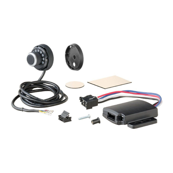
TABLE OF CONTENTS CONTROLS & COMPONENTS TOOLS LIST Controls & Components page 2 1. Main module 1. Drill 2. Main module adhesive pad 2. Drill bit, 5/16" Tools List page 2 3. LED display rotary knob 3. Phillips screwdriver Before You Begin page 3 4. -
Page 3: Before You Begin
(see the CURT catalog for availability) availability, location and installation. If the mating plug supplied with the vehicle is no longer available, a CURT quick plug can be used. See the • CURT #51515 / #51516 - quick plug with pigtails CURT catalog for application information. -
Page 4: Wiring Diagram
WIRING DIAGRAM CURTMFG.COM • NEED ASSISTANCE? 877.287.8634 51170-INS-RC PAGE 4 • • •... -
Page 5: Mounting The Led Display Rotary Knob
MOUNTING THE LED DISPLAY ROTARY KNOB Install the LED display rotary knob before installing the main module. There are two options for mounting the LED display knob in the vehicle. Notes: Do not insert terminals into the plug connector at this time. When inserting the LED display rotary knob into the base plate, ensure the top of the LED arc is facing the upright direction. - Page 6 MOUNTING THE LED DISPLAY ROTARY KNOB - CONTINUED Base plate installation, surface adhesive mount option 1. Determine a suitable mounting location for the LED display knob. a. The LED display must be mounted securely to a solid surface. b. The LED display must be easily reached by the driver. 2.
-
Page 7: Mounting The Main Module
MOUNTING THE MAIN MODULE 1. Determine a suitable mounting location for the main module. a. The unit must be mounted securely to a solid surface, preferably under the dash (Fig 1). b. The unit needs to be connected to the LED display rotary knob. Figure 1 2. -
Page 8: Modes & Indicators On The Led Display
MODES & INDICATORS ON THE LED DISPLAY Manual Control (red progression) Manual brake control activation is used in situations where a slow The LED display shows the output setting when the control is activated. reduction in speed is desirable. As the manual control is pushed, the It is used to setup and monitor the brake control and can be used when brake control begins to apply the trailer brakes. - Page 9 Manual Control (red progression) - continued Output Control (green to red progression) • Pressing and holding the button during any The output control establishes the maximum amount of power available to the trailer brakes when braking. The only exception mode activates the manual brake output would be when the manual control is set up for 100% braking.
- Page 10 Sensitivity Control (blue to red progression) Overload Indicator (red and yellow flashing) The sensitivity control adjusts trailer brake aggressiveness. • Indicates when the brake control is Sensitivity adjustment has no effect on the manual control. in an overload or short-circuit condition The sensitivity control can be adjusted for individual driver •...
-
Page 11: Set Manual Control Output And Brake Light Switches
SET MANUAL CONTROL OUTPUT INITIAL SETUP AND BRAKE LIGHT SWITCHES Once all electrical connections are complete, plug the trailer's electrical connector into the tow vehicle's plug while parked on a level surface. There are two small switches located at the front of the unit, Connecting the trailer initiates the mounting position calibration mode. -
Page 12: Test Drive & Adjustment
3. Alligator clip test leads OR wire and wire nuts made and will then go into brightness mode. 4. CURT #51515 / #51516 quick plug with pigtails OR push pins Starting with the output adjustment, drive forward on a dry and level Note: If a quick plug pigtail is not available, push pins can be used to paved or concrete surface. - Page 13 BENCH TEST - CONTINUED Brake Control Setup - continued Ensure the Spectrum is level to the bench surface and connect the After testing, disconnect the wiring from the positive terminal ™ signal wire of the bulb to the blue brake output wire of the Spectrum of the 12V battery ensuring the exposed contacts do not make contact.
-
Page 14: Troubleshooting Guide
TROUBLESHOOTING GUIDE Condition Display Problem Cause Possible Solution LED display has no LEDs lit up No power to brake control, no ground, reversed Check brake control wiring black and white wire on the main module, LED display plug connector not wired correctly LED display is lit red Red wire connected to ground side of stoplight Check and repair connections... - Page 15 TROUBLESHOOTING GUIDE - CONTINUED Condition Display Problem Cause Possible Solution LED display shows blue LEDs at the edges No connection between brake control Confirm connection to trailer connected, and trailer brakes - blue circuit confirm connector terminal positions, check trailer brakes No trailer brakes, pedal or manual Mis-wired trailer connector Confirm trailer connector terminal position...
- Page 16 At CURT, customer is king. We value your feedback and we use that information to make improvements on our products. Please, take a minute and let us know how we are doing.
Need help?
Do you have a question about the Spectrum 51170 and is the answer not in the manual?
Questions and answers