Table of Contents
Advertisement
Quick Links
INSTALLATION MANUAL
Level of Difficulty
Easy
Installation difficulty levels are based on time
and effort involved and may vary depending on
the installer level of expertise, condition of the
vehicle and proper tools and equipment.
Electrical Ratings
Signal circuits
3.0-amps per side
Tail / Running Circuits
6.0-amps total
Check vehicle owner's manual or contact
the vehicle manufacturer for more information.
Wiring Location(s)
P3 and P4, S3 and S4
Wiring Location Guide*
for Passenger Cars (P)
P3 Behind driver side taillight
housing, inside of trunk
P4 Behind passenger side taillight
housing, inside of trunk
P1 P3
P4 P2
P5
P6
P7
* Representative vehicle shown
Wiring Location Guide*
for SUVs and Vans (S)
S3
Behind driver side rear access panel
S4
Behind passenger side rear access panel
S10
S9
S1
S2
S3
S4
S8
S5
S6
S7
* Representative vehicle shown
56093-INS-RC
•
01/14/2021
•
Do not exceed product rating or tow vehicle lamp load rating, whichever is lower.
The battery connection must be fuse-protected, 10-amp max. Exceeding
the product rating can cause loss of warranty, overheating and potential fire.
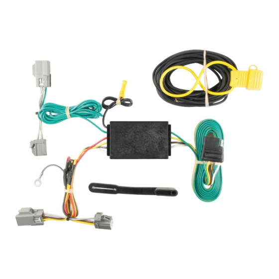
Product Photo
Hardware Photo
NOTICE
Before you begin installation, read all instructions thoroughly.
Proper tools will improve the quality of installation and reduce the time required.
All steps must be followed to ensure the product will function properly. Once installed,
test for proper function by using a test light or connecting a properly wired trailer.
Maintenance
Periodic inspection of all wires and connections should be performed
to ensure there is no visible damage or loose connections.
Tools Required
Ratchet
Socket, 8mm
Socket extension
ECN7905
•
PAGE 1 OF 7
Panel trim removal tool Wire crimper
Pliers
Wire stripper
Cutting tool
Heat gun
Paint marker
Electrical tape
--
Advertisement
Table of Contents

Related Manuals for curt 56093


Summary of Contents for curt 56093
- Page 1 Tools Required Ratchet Panel trim removal tool Wire crimper Paint marker Socket, 8mm Pliers Wire stripper Electrical tape Socket extension Cutting tool Heat gun * Representative vehicle shown 56093-INS-RC • 01/14/2021 • ECN7905 • PAGE 1 OF 7...
- Page 2 Insert the custom wiring end with yellow wire between the separated connectors. Make sure the connectors are fully inserted with locking tabs in place. 56093-INS-RC • 01/14/2021 • ECN7905 •...
- Page 3 Use a panel trim removal tool to remove the scuff panel by pulling out on the bottom and then up. Take care not to damage the alignment tabs on the back. 56093-INS-RC • 01/14/2021 • ECN7905 •...
- Page 4 Secure any loose wires with the provided cable ties. Reinstall all items removed during install. If it was disconnected at the beginning of the installation, reconnect the negative battery terminal. Install the provided 4-flat dust cover to help prevent corrosion. 56093-INS-RC • 01/14/2021 •...
- Page 5 Use a panel trim removal tool to loosen the cargo hook fastener cover. Use an 8mm socket to remove the cargo hook. Repeat on the other side of the vehicle. 56093-INS-RC • 01/14/2021 • ECN7905 •...
- Page 6 Secure any loose wires with the provided cable ties. Reinstall all items removed during install. If it was disconnected at the beginning of the installation, reconnect the negative battery terminal. Install the provided 4-flat dust cover to help prevent corrosion. 56093-INS-RC • 01/14/2021 •...
- Page 7 (haga una perforación Brun - Feu arrièr Marrón - Luces traseras rojo del freno debe estar conectado a tierra de 3/32" si es necesario) 56093-INS-RC • 01/14/2021 • ECN7905 • PAGE 7 OF 7...
Need help?
Do you have a question about the 56093 and is the answer not in the manual?
Questions and answers