
Related Manuals for Metrohm 940 Professional IC Vario ONE/LPG


Summary of Contents for Metrohm 940 Professional IC Vario ONE/LPG
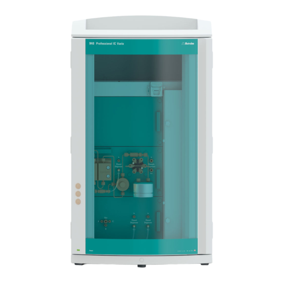
- Page 1 940 Professional IC Vario 940 Professional IC Vario ONE/LPG Manual 8.940.8005EN / 2017-07-31...
- Page 3 Metrohm AG CH-9100 Herisau Switzerland Phone +41 71 353 85 85 Fax +41 71 353 89 01 info@metrohm.com www.metrohm.com 940 Professional IC Vario 940 Professional IC Vario ONE/LPG 2.940.1150 Manual 8.940.8005EN / 2017-07-31...
- Page 4 Technical Communication Metrohm AG CH-9100 Herisau techcom@metrohm.com This documentation is protected by copyright. All rights reserved. This documentation has been prepared with great care. However, errors can never be entirely ruled out. Please send comments regarding possible errors to the address above.
-
Page 5: Table Of Contents
3.10 Installing an inline filter ............. 27 3.11 Installing the pulsation absorber ........27 3.12 Injection valve ..............28 3.13 Installing the conductivity detector ........30 3.14 Installing the amperometric detector ....... 31 ■■■■■■■■ 940 Professional IC Vario ONE/LPG (2.940.1150) - Page 6 Separating efficiency .............. 74 5.14.2 Protecting the separation column .......... 74 5.14.3 Storing the separation column ..........74 5.14.4 Regenerating the separation column ........74 5.15 Quality management and qualification with Metrohm ... 75 ■■■■■■■■ 940 Professional IC Vario ONE/LPG (2.940.1150)
- Page 7 High-pressure pump ............82 7.10 Injection valve ..............83 7.11 Detector ................83 7.12 Sample degasser ..............83 7.13 Low-pressure gradient ............83 7.14 Power connection ............... 84 7.15 Interfaces ................84 8 Accessories Index ■■■■■■■■ 940 Professional IC Vario ONE/LPG (2.940.1150)
- Page 8 Removing the piston cartridge from the pump head ......64 Figure 19 Inserting the piston seal into the tool ..........65 Figure 20 Parts of the piston cartridge ............66 Figure 21 Inline filter – Removing the filter ............70 ■■■■■■■■ 940 Professional IC Vario ONE/LPG (2.940.1150)
-
Page 9: Introduction
The software controls and monitors the instrument, evaluates the measured data and manages it in a data- base. The 940 Professional IC Vario ONE/LPG consists of the following modules: Housing The sturdy housing contains the instrument's electronic components, including their interfaces and three connections for separation columns (two of which are built into the installed column thermostat). - Page 10 Detector Metrohm offers a series of different detectors for various analysis tasks. A suitable detector type must be ordered as a separate device. Sample degasser The sample degasser removes gas bubbles and dissolved gases from the sample.
-
Page 11: Intended Use
(start-up, operating hours, injections etc) are stored. Intended use The 940 Professional IC Vario ONE/LPG is used for the determination of cations and anions without suppression using ion chromatography when the complex separation problem requires the use of gradients. -
Page 12: Electrical Safety
The electrical safety when working with the instrument is ensured as part of the international standard IEC 61010. WARNING Only personnel qualified by Metrohm are authorized to carry out service work on electronic components. WARNING Never open the housing of the instrument. The instrument could be damaged by this. -
Page 13: Tubing And Capillary Connections
The correct disposal of your old instrument will help to prevent negative effects on the environment and public health. More details about the disposal of your old instrument can be obtained from your local authorities, from waste disposal companies or from your local dealer. ■■■■■■■■ 940 Professional IC Vario ONE/LPG (2.940.1150) -
Page 14: Symbols And Conventions
WARNING This symbol draws attention to a possible biological hazard. CAUTION This symbol draws attention to possible damage to instruments or instrument parts. NOTE This symbol highlights additional information and tips. ■■■■■■■■ 940 Professional IC Vario ONE/LPG (2.940.1150) -
Page 15: Overview Of The Instrument
Offers space for two embedded detectors additional accessories. and additional accessories. Column holder Column thermostat For a third separation column outside the With two column holders for two separation column thermostat. columns. Inline filter Sample degasser ■■■■■■■■ 940 Professional IC Vario ONE/LPG (2.940.1150) - Page 16 Eluent degasser 10 Base tray Two eluent degassers for two additional elu- With leak sensor. ents. 11 Low-pressure mixing valve 12 Purge valve For deaerating the high-pressure pump. 13 High-pressure pump 14 Eluent degasser ■■■■■■■■ 940 Professional IC Vario ONE/LPG (2.940.1150)
-
Page 17: Rear
Up to two vac- tor chamber. uum pumps can be installed in an instru- ment. Only two transport locking screws are used if just one vacuum pump is installed. ■■■■■■■■ 940 Professional IC Vario ONE/LPG (2.940.1150) -
Page 18: Feed-Throughs For Capillaries And Cables
Openings on the door (see Figure 3, page 11) ■ Openings on the back panel ■ Ducts between the instrument and the base tray as well as between ■ the instrument and the bottle holder (see Figure 5, page 13) ■■■■■■■■ 940 Professional IC Vario ONE/LPG (2.940.1150) -
Page 19: Figure 3 Feed-Throughs On The Door
The two Luer connections above are not actually openings; the capillaries are fastened to the Luer connection from within using PEEK pressure screws. You can use a syringe to inject or draw out liquid from the out- side. ■■■■■■■■ 940 Professional IC Vario ONE/LPG (2.940.1150) -
Page 20: Figure 4 Openings For Capillaries And Cables
The capillaries can be fed to the front of the instrument from both sides of the instrument and from the front of the instrument to the back of the instrument. ■■■■■■■■ 940 Professional IC Vario ONE/LPG (2.940.1150) -
Page 21: Figure 5 Ducts For Capillaries
■■■■■■■■■■■■■■■■■■■■■■ 2 Overview of the instrument Figure 5 Ducts for capillaries ■■■■■■■■ 940 Professional IC Vario ONE/LPG (2.940.1150) -
Page 22: Installation
High-pressure pump, purge valve, inline filter, pulsation absorber, separation columns 6.2744.090 Pressure screw, long MCS, sample degasser, 10- port valve Pressure screws are tightened and loosened by hand. A tool is not nee- ded. ■■■■■■■■ 940 Professional IC Vario ONE/LPG (2.940.1150) - Page 23 (6.2739.000). ■ In order to achieve optimum analysis results, capillary connections in an IC system must be absolutely tight and free of dead volume. Dead volume ■■■■■■■■ 940 Professional IC Vario ONE/LPG (2.940.1150)
- Page 24 2 Heat the colored sleeve, e.g. with a hairdryer. The colored sleeve shrinks and adapts to the shape of the capillary. NOTE In order to arrange capillaries more clearly, they can be bundled with the spiral band (6.1815.010). ■■■■■■■■ 940 Professional IC Vario ONE/LPG (2.940.1150)
-
Page 25: Removing The Handle
The handle can be removed once the instrument is in place in the lab. Accessories You do not need any accessories for the following work steps. Removing the handle 1 Removing the handle Unscrew the four knurled screws. ■ Remove the handle. ■ ■■■■■■■■ 940 Professional IC Vario ONE/LPG (2.940.1150) -
Page 26: Removing Transport Locking Screws
Transport locking screws For the vacuum pump. For the high-pressure pump. Transport locking screws For an additional high-pressure pump in the bottom drawer. 1 Remove all of the transport locking screws with the hex key. ■■■■■■■■ 940 Professional IC Vario ONE/LPG (2.940.1150) -
Page 27: Connecting The Drainage Tubing And Leak Sensor
Accessories For this step you need the following parts from the accessory kit: Vario/ Flex Basic (6.5000.000): 2 × silicone tubing (6.1816.020) ■ Y connector (6.1807.010) ■ You also need scissors. ■■■■■■■■ 940 Professional IC Vario ONE/LPG (2.940.1150) - Page 28 Attach the loose end to the right-side drainage tubing connection on the base tray. 6 Attach one end of the second piece of silicone tubing to the left-side drainage tubing connection on the base tray. ■■■■■■■■ 940 Professional IC Vario ONE/LPG (2.940.1150)
-
Page 29: Connecting The Leak Sensor
The capillaries are fed through small openings on the inner front edge, so that they do not get pinched when the door is closed. The column thermostat is completely connected. No installation work is required. ■■■■■■■■ 940 Professional IC Vario ONE/LPG (2.940.1150) -
Page 30: Connecting The Eluent Bottle
Push the loose end of the eluent aspiration tubing through the ■ M8 opening of the bottle cap and screw it on for the time being. Figure 7 Installing the eluent bottle cap ■■■■■■■■ 940 Professional IC Vario ONE/LPG (2.940.1150) - Page 31 Place the loose end of the eluent aspiration tubing into the aspira- ■ tion filter. The end of the tubing should reach approximately to the center of the aspiration filter. Tighten the aspiration filter to the filter holder. ■ ■■■■■■■■ 940 Professional IC Vario ONE/LPG (2.940.1150)
-
Page 32: Figure 8 Installing Tubing Weighting And Aspiration Filter
Then fix it in place using the M8 tubing nipple. Seal the M6 opening on the bottle cap with the M6 threaded ■ stopper from the accessory set. ■■■■■■■■ 940 Professional IC Vario ONE/LPG (2.940.1150) - Page 33 Fill the adsorber tube and close it again using the plastic cover. Insert the adsorber tube into the bottle cap's large opening. Fas- ■ ten it to the bottle cap using the SGJ clip (6.2023.020). ■■■■■■■■ 940 Professional IC Vario ONE/LPG (2.940.1150)
-
Page 34: Connecting The Eluent Degasser
If the high-pressure pump is used to pump a low-pressure gradient, then the input for the high-pressure pump has to be connected to the low- pressure gradient module. Follow the instructions in chapter Installing the low-pressure gradient, page 35. ■■■■■■■■ 940 Professional IC Vario ONE/LPG (2.940.1150) -
Page 35: Installing An Inline Filter
The pulsation absorber is installed between the high-pressure pump and the injection valve. It protects the separation column from damage caused by pressure fluctuations, e.g. when the injection valve is switched, and reduces interfering pulsations during highly sensitive measurements. ■■■■■■■■ 940 Professional IC Vario ONE/LPG (2.940.1150) -
Page 36: Injection Valve
The quantity of sample solution injected is determined by: the volume of the sample loop or ■ by an 800 Dosino when the Metrohm intelligent Partial Loop Injection ■ Technique (MiPT), the Metrohm intelligent Pick-up Injection Technique (MiPuT) or the Metrohm Inline Preconcentration (MiPCT, MiPCT-ME) is used. -
Page 37: Figure 12 Exchanging The Sample Loop
Only use PEEK pressure screws (6.2744.010) to connect capillaries and the sample loop to the injection valve. Figure 12 Exchanging the sample loop Pressure screw Sample loop Fastened to Port 6. Pressure screw Fastened to Port 3. ■■■■■■■■ 940 Professional IC Vario ONE/LPG (2.940.1150) -
Page 38: Installing The Conductivity Detector
(6.2744.040). Accessories For this step, you need the following accessories: Coupling (6.2744.040) ■ 2 × pressure screw (6.2744.010) ■ ■■■■■■■■ 940 Professional IC Vario ONE/LPG (2.940.1150) -
Page 39: Installing The Amperometric Detector
The rinsing time increases by at least two minutes when the sample degasser is connected. Accessories For this step, you need the following accessories: 2 × pressure screw, long (6.2744.090) ■ PTFE capillary (6.1803.040) ■ ■■■■■■■■ 940 Professional IC Vario ONE/LPG (2.940.1150) - Page 40 3 Connecting the inlet capillary Push a long pressure screw over one end of the PTFE capillary ■ (6.1803.040) and tighten the pressure screw to the inlet of the sample degasser (labeled In). ■■■■■■■■ 940 Professional IC Vario ONE/LPG (2.940.1150)
-
Page 41: Low-Pressure Gradient
The optimal assignment of eluents to the valves depends on the applica- tion and is outlined in the Application Notes. You can only achieve a reproducible gradient profile if this eluent-valve assignment remains unchanged. Each eluent is degassed via a separate eluent degasser. ■■■■■■■■ 940 Professional IC Vario ONE/LPG (2.940.1150) -
Page 42: Figure 13 Low-Pressure Gradient
Connected to the outlet of the eluent degas- Has to be connected to the inlet of the high- pressure pump. ser (13- Eluent inlet A Has to be connected to the eluent degasser in the middle plug-in. ■■■■■■■■ 940 Professional IC Vario ONE/LPG (2.940.1150) -
Page 43: Installing The Low-Pressure Gradient
2 Removing the stoppers Remove the stopper at the eluent inlet A. ■ Remove the stopper from the eluent outlet (labeled Out). ■ ■■■■■■■■ 940 Professional IC Vario ONE/LPG (2.940.1150) -
Page 44: Connecting The Instrument To A Computer
Connecting the instrument to a computer NOTE If the instrument is connected to the computer, then it must be switched off. Accessories For this step, you need the following accessories: USB connecting cable (6.2151.020) ■ ■■■■■■■■ 940 Professional IC Vario ONE/LPG (2.940.1150) -
Page 45: Connecting The Instrument To The Power Grid
Unplug the power plug immediately if you suspect that moisture has ■ gotten inside the instrument. Only personnel who have been issued Metrohm qualification may ■ perform service and repair work on electrical and electronic parts. ■■■■■■■■... -
Page 46: Initial Start-Up
Also see: MagIC Net Tutorial and online help. 2 Preparing the instrument Ensure that the eluent aspiration tubing is immersed in the eluent ■ and that there is enough eluent in the eluent bottle. Switch on the instrument. ■ ■■■■■■■■ 940 Professional IC Vario ONE/LPG (2.940.1150) - Page 47 Switch off the high-pressure pump in MagIC Net. ■ Seal the purge valve using the rotary knob. ■ Remove the syringe from the purge needle. ■ Pull the purge needle out of the purge capillary. ■ ■■■■■■■■ 940 Professional IC Vario ONE/LPG (2.940.1150)
-
Page 48: Connecting And Rinsing The Guard Column
Connecting and rinsing the guard column Guard columns protect separation columns and significantly increase their service life. The guard columns available from Metrohm are either actual guard columns or guard column cartridges used together with a cartridge holder. The process of installing a guard column cartridge into the corre- sponding holder is described in the guard column leaflet. - Page 49 When inserting the guard column, ensure that it is inserted cor- rectly based on the marked flow direction (if specified). Fasten the inlet of the guard column to the column inlet capillary ■ using a short pressure screw (6.2744.070). ■■■■■■■■ 940 Professional IC Vario ONE/LPG (2.940.1150)
-
Page 50: Connecting The Separation Column
NOTE Information regarding which separation column is suitable for your application can be found in the Metrohm Column Program, the product information for the separation column or it can be obtained through your representative. - Page 51 (follow the information provided by the manufacturer). NOTE Connect the separation column only after the initial start-up of the instrument. Until that point, insert a coupling (6.2744.040) instead of the guard column and separation column. ■■■■■■■■ 940 Professional IC Vario ONE/LPG (2.940.1150)
- Page 52 ■■■■■■■■■■■■■■■■■■■■■■ 3.22 Connecting the separation column Connecting the separation column 1 Removing the stoppers Remove the stoppers from the separation column. ■ ■■■■■■■■ 940 Professional IC Vario ONE/LPG (2.940.1150)
- Page 53 6 Inserting the separation column Insert the separation column with the chip into the column holder ■ until you hear it snap in place. The separation column is now detected by MagIC Net. ■■■■■■■■ 940 Professional IC Vario ONE/LPG (2.940.1150)
-
Page 54: Conditioning
Ensure that the eluent aspiration tubing is immersed in the eluent ■ and that there is enough eluent in the eluent bottle. 3 Starting equilibration Start the equilibration in MagIC Net: Workplace ▶ Run ▶ Equili- ■ bration ▶ Start HW. ■■■■■■■■ 940 Professional IC Vario ONE/LPG (2.940.1150) - Page 55 4 Conditioning the system Continue rinsing the system with eluent until the desired stability level for the baseline has been attained . The instrument is now ready for measuring samples. ■■■■■■■■ 940 Professional IC Vario ONE/LPG (2.940.1150)
-
Page 56: Operation
■■■■■■■■■■■■■■■■■■■■■■ 4 Operation The 940 Professional IC Vario ONE/LPG is operated solely using the MagIC Net software. You can find information on operating the software in the tutorial for MagIC Net or in the online help. ■■■■■■■■ 940 Professional IC Vario ONE/LPG (2.940.1150) -
Page 57: Operation And Maintenance
Maintenance by Metrohm Service Maintenance of the instrument is best carried out as part of an annual service performed by specialist personnel from Metrohm. A shorter main- tenance interval is recommended if you frequently work with caustic and corrosive chemicals. Metrohm Service offers every form of technical advice for maintenance and service of all Metrohm instruments. -
Page 58: Shutting Down And Recommissioning
3 Rinse the IC system for 15 minutes with methanol/ultrapure water mixture (1:4). 4 Optional: Only if the IC system is equipped with a suppressor. In the software, switch the Metrohm Suppressor Module (MSM) twice during the rinsing process at five-minute intervals in each case (STEP command). -
Page 59: Capillary Connections
Column thermostat – Replacing the capillaries There are two preheating grooves on both of the column thermostat's side walls, where the column inlet capillary has already been inserted and fastened in place with a holder plate. ■■■■■■■■ 940 Professional IC Vario ONE/LPG (2.940.1150) -
Page 60: Figure 14 Column Thermostat
5.4 Column thermostat – Replacing the capillaries Figure 14 Column thermostat Openings Preheating grooves For feeding capillaries into and out of the For regulating the temperature of the eluent. instrument. Column holder With column recognition. For fastening the column. ■■■■■■■■ 940 Professional IC Vario ONE/LPG (2.940.1150) -
Page 61: Handling The Eluent
"p.a.". They may be diluted only by using ultrapure water (resistance > 18.2 MΩ*cm). (These specifications apply generally for all reagents used in ion chromatography.) Newly manufactured eluents always need to be microfiltered (0.45 µm fil- ter). ■■■■■■■■ 940 Professional IC Vario ONE/LPG (2.940.1150) -
Page 62: Changing The Eluent
You can find these parts in the accessory kit: Vario/Flex Basic (6.5000.000) Wrench (6.2621.050) ■ Loosening the connecting tubing Loosen the clamping screws with the wrench. ■ Unscrew the clamping screws by hand and pull them out of the ■ connector. ■■■■■■■■ 940 Professional IC Vario ONE/LPG (2.940.1150) -
Page 63: Notes On Operating The High-Pressure Pump
In order to protect the pump seals, ensure that the pump is never oper- ■ ated dry. Therefore ensure that the eluent supply is correctly connected and that there is enough eluent in the eluent bottle each time before turning on the pump. ■■■■■■■■ 940 Professional IC Vario ONE/LPG (2.940.1150) -
Page 64: Servicing The High-Pressure Pump
5.8 Servicing the high-pressure pump Servicing the high-pressure pump NOTE You can find a video sequence for this task in the Multimedia Guide IC Maintenance or on the Internet at http://ic-help.metrohm.com/. Figure 15 High-pressure pump – Parts Pressure screw, short (6.2744.070) Outlet valve holder Fastened to the outlet valve holder. - Page 65 Internet at http://ic-help.metrohm.com/. Servicing the outlet valve and inlet valve Accessories For this step, you need the following accessories: You can find these parts in the accessory kit: Vario/Flex Basic (6.5000.000). Adjustable wrench (6.2621.000) ■ ■■■■■■■■ 940 Professional IC Vario ONE/LPG (2.940.1150)
- Page 66 RBS™ solution or acetone. The rinsing solution may only come out at the valve outlet. The outlet valve must be replaced if it is still clogged after cleaning. ■■■■■■■■ 940 Professional IC Vario ONE/LPG (2.940.1150)
- Page 67 ¼ turn using the adjustable wrench (3). Tighten the connection capillary to the auxiliary piston back onto ■ the outlet valve holder. ■■■■■■■■ 940 Professional IC Vario ONE/LPG (2.940.1150)
- Page 68 RBS™ solution or acetone. The rinsing solution may only come out at the valve outlet. The inlet valve must be replaced if it is still clogged after cleaning. ■■■■■■■■ 940 Professional IC Vario ONE/LPG (2.940.1150)
- Page 69 You can find these parts in the accessory kit: Vario/Flex Basic (6.5000.000). 4 mm hex key (6.2621.030) ■ Removing the pump head Prerequisites: Is the high-pressure pump switched off? ■ Has the pressure been released? ■ Is the instrument switched off? ■ ■■■■■■■■ 940 Professional IC Vario ONE/LPG (2.940.1150)
- Page 70 Servicing the piston Carry out the following work on both pistons in turn. Servicing a piston consists of the following tasks: Replace the piston seal. Clean or replace the zirconium oxide piston. Reinstall the piston. ■■■■■■■■ 940 Professional IC Vario ONE/LPG (2.940.1150)
-
Page 71: Figure 16 High-Pressure Pump - Cross-Section
(6.5000.000). Adjustable wrench (6.2621.000) ■ Tool for piston seals (6.2617.010) consisting of a tip (17-1) for remov- ■ ing the old piston seal and a sleeve (17-2) for inserting the new piston seal. ■■■■■■■■ 940 Professional IC Vario ONE/LPG (2.940.1150) -
Page 72: Figure 17 Tool For Piston Seal (6.2617.010)
Loosen the piston cartridge (18-1) using the adjustable wrench and then unscrew it from the pump head by hand. Set it aside. 2 Removing the backup ring Shake the backup ring (18-2) out of the piston opening. Set it aside. ■■■■■■■■ 940 Professional IC Vario ONE/LPG (2.940.1150) -
Page 73: Figure 19 Inserting The Piston Seal Into The Tool
Press the seal into the pump head recess using the wide end of the tip (17-1) of the tool. Cleaning or replacing the zirconium oxide piston Prerequisites: ■■■■■■■■ 940 Professional IC Vario ONE/LPG (2.940.1150) -
Page 74: Figure 20 Parts Of The Piston Cartridge
Place the backup ring you put aside with the remaining parts. ■ Figure 20 Parts of the piston cartridge Piston cartridge screw Retaining washer Zirconium oxide piston (6.2824.070) Spring retainer Spring (6.2824.060) Inner plastic sleeve Protects from metallic abrasion. Piston cartridge Backup ring ■■■■■■■■ 940 Professional IC Vario ONE/LPG (2.940.1150) - Page 75 Clean the second piston cartridge in the same way. Mounting the pump head Accessories For this step, you need the following accessories: You can find these parts in the accessory kit: Vario/Flex Basic (6.5000.000). ■■■■■■■■ 940 Professional IC Vario ONE/LPG (2.940.1150)
- Page 76 The bore hole with the greatest depth must therefore be aligned with the longest bolt. Push the pump head onto the four fastening bolts (1). ■ Tighten the four fastening screws using the hex key (6.2621.030) ■ alternating crosswise. ■■■■■■■■ 940 Professional IC Vario ONE/LPG (2.940.1150)
-
Page 77: Servicing The Inline Filter
Servicing the inline filter NOTE You can find a video sequence for this task in the Multimedia Guide IC Maintenance or on the Internet at http://ic-help.metrohm.com/. Maintenance interval The filter must be replaced at least every 3 months; it may need to be replaced more frequently, depending on the application. -
Page 78: Figure 21 Inline Filter - Removing The Filter
3 Unscrewing the filter screw Use two adjustable wrenches (6.2621.000) to loosen the filter screw (21-2) from the filter housing (21-1) and unscrew it by hand. 4 Removing the filter Remove the old filter (21-3) using tweezers. ■■■■■■■■ 940 Professional IC Vario ONE/LPG (2.940.1150) - Page 79 4 Rinsing the inline filter Dismantle the guard column (if present) and the separation col- ■ umn and replace with a coupling (6.2744.040). Rinse the instrument with eluent. ■ Reinsert the columns after 10 minutes. ■ ■■■■■■■■ 940 Professional IC Vario ONE/LPG (2.940.1150)
-
Page 80: Servicing The Pulsation Absorber
1 Emptying the sample path Pump air through the sample path (pump tubing, tubing connec- tions, capillary in the degasser, sample loop) for several minutes until all liquid is displaced by the air. ■■■■■■■■ 940 Professional IC Vario ONE/LPG (2.940.1150) - Page 81 A. The smaller this ratio, the smaller the amount of sample carry- over. This ratio can be changed by varying the rinsing time. This can be used to determine the required rinsing time for the application. ■■■■■■■■ 940 Professional IC Vario ONE/LPG (2.940.1150)
-
Page 82: Separation Column
You can find detailed information on the separation columns available from Metrohm in the leaflet provided along with your separation column, in the Metrohm IC Column Program (available from your Metrohm representative) or on the Internet at http://www.metrohm.com... -
Page 83: Quality Management And Qualification With Metrohm
Metrohm offers you comprehensive support in implementing quality man- agement measures for instruments and software. Qualification Please contact your local Metrohm representative for support in qualifica- tion of instruments and software. The Installation Qualification (IQ) and Operational Qualification (OQ) are offered by Metrohm represen- tatives as a service. -
Page 84: Troubleshooting
Check the eluent bottle cap (see Chapter ■ eluent is evaporating. 3.7, page 22). Constantly stir the eluent. ■ The pressure in the The inline filter Replace the filter (6.2821.130) . system markedly (6.2821.120) is blocked. increases. ■■■■■■■■ 940 Professional IC Vario ONE/LPG (2.940.1150) - Page 85 Replace the separation column (see "Con- ■ necting the separation column", page 44). Note: Samples should always be microfiltered . Injection valve – blocked. Have the valve cleaned (by a Metrohm service engineer). The retention times Eluent - Incorrect concen- Create eluent with correct concentration.
- Page 86 29). Sample – There are gas Use the sample degasser . bubbles in the sample. Sample – The rinsing vol- Increase the rinsing time (see Chapter 5.13, ume is too small. page 72). ■■■■■■■■ 940 Professional IC Vario ONE/LPG (2.940.1150)
- Page 87 Request Metrohm Service. Vacuum is not being Eluent degasser – Vacuum Seal the Vacuum connector tightly with a ■ built connection on the rear of threaded stopper (6.1446.040). the instrument is not (tightly) sealed. ■■■■■■■■ 940 Professional IC Vario ONE/LPG (2.940.1150)
-
Page 88: Technical Specifications
Ambient conditions Operation Ambient tem- +5 - +45 °C perature Humidity 20 - 80% relative humidity Storage Ambient tem- –20 - +70 °C perature Transport Ambient tem- –40 - +70 °C perature ■■■■■■■■ 940 Professional IC Vario ONE/LPG (2.940.1150) -
Page 89: Housing
Down to 20 °C below the ambient temperature Temperature ±0.2 °C reproducibility Stability < 0.05 °C Heating time < 30 minutes from 20 to 50 °C Cooling time < 40 minutes from 50 to 20 °C ■■■■■■■■ 940 Professional IC Vario ONE/LPG (2.940.1150) -
Page 90: Eluent Degasser
The shutdown mechanism is inactive at 0 MPa ■ The shutdown mechanism becomes active two minutes after sys- ■ tem start The pump is automatically shut down after three piston strokes ■ below the minimum pressure limit ■■■■■■■■ 940 Professional IC Vario ONE/LPG (2.940.1150) -
Page 91: Injection Valve
No restriction (except PFC) vents Time to establish < 60 s vacuum 7.13 Low-pressure gradient Profile Step, linear, convex and concave Valve type Normally closed Degasser One eluent degasser for each of the three eluents ■■■■■■■■ 940 Professional IC Vario ONE/LPG (2.940.1150) -
Page 92: Power Connection
2 15-pin high-density D-sub (female) (labeled Detector 1 and Detec- tor 2) Column recogni- 3 (including 2 in the column thermostat ) tion Leak sensor 1 jack plug (labeled Leak Sensor) Further connec- 1 15-pin D-sub (female) (labeled Extension Module) ■ tions ■■■■■■■■ 940 Professional IC Vario ONE/LPG (2.940.1150) -
Page 93: Accessories
The PDF file with the accessories data will be created. NOTE When you receive your new instrument, we recommend downloading the accessories list from the Internet, printing it out and keeping it together with the manual for reference purposes. ■■■■■■■■ 940 Professional IC Vario ONE/LPG (2.940.1150) -
Page 94: Index
Power connection ..37, 38, 84 Injection valve ......2 Door ........51 Power consumption ....84 Installation ......28 Drainage tubing Power cord ....... 38 Maintenance ...... 72 Installation ......19 Power supply unit ..... 84 ■■■■■■■■ 940 Professional IC Vario ONE/LPG (2.940.1150) - Page 95 Column thermostat .... 81 Safety instructions ...... 3 See also "Injection valve" ..28 Detector ......84 Safety shutdown ...... 82 Eluent degasser ....82 Sample High-pressure pump ... 82 Carry-over ......72 ■■■■■■■■ 940 Professional IC Vario ONE/LPG (2.940.1150)
Need help?
Do you have a question about the 940 Professional IC Vario ONE/LPG and is the answer not in the manual?
Questions and answers