
Subscribe to Our Youtube Channel
Related Manuals for Metrohm 940 Professional IC Vario ONE/SeS/PP/MB


Summary of Contents for Metrohm 940 Professional IC Vario ONE/SeS/PP/MB
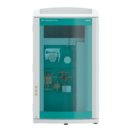
- Page 1 940 Professional IC Vario 940 Professional IC Vario ONE/SeS/PP/MB Manual 8.940.8030EN / 2022-11-15...
- Page 3 Metrohm AG CH-9100 Herisau Switzerland +41 71 353 85 85 info@metrohm.com www.metrohm.com 940 Professional IC Vario 940 Professional IC Vario ONE/SeS/PP/MB 2.940.1580 Manual 8.940.8030EN / 2022-11-15...
- Page 4 Disclaimer Deficiencies arising from circumstances that are not the responsibility of Metrohm, such as improper storage or improper use, etc., are expressly excluded from the warranty. Unauthorized modifications to the product (e.g. conversions or attachments) exclude any liability on the part of the manufacturer for resulting damage and its consequences.
-
Page 5: Table Of Contents
Installing the drainage tubing ..........23 4.5.2 Connecting the leak sensor ............ 25 Column thermostat ............25 Connecting the eluent bottle ..........26 Connecting the eluent degasser ........30 Installing the high-pressure pump ........30 940 Professional IC Vario ONE/SeS/PP/MB (2.940.1580) ■■■■■■■■... - Page 6 4.12 Injection valve ..............32 4.13 Metrohm Suppressor Module (MSM) ....... 34 4.13.1 Inserting the rotors ..............35 4.13.2 Connecting the Metrohm Suppressor Module (MSM) ..... 38 4.14 Peristaltic pump ..............43 4.14.1 Installing the peristaltic pump ..........43 4.14.2 Mode of operation for the peristaltic pump ......
- Page 7 Notes for operating the Metrohm Suppressor Module (MSM) ................... 92 6.12.2 Taking care of the suppressor housing ........93 6.12.3 Servicing the Metrohm Suppressor Module (MSM) ....93 6.13 Peristaltic pump ..............101 6.13.1 Notes on operating the peristaltic pump ......101 6.13.2 Servicing the peristaltic pump ..........
- Page 8 Table of contents ■■■■■■■■■■■■■■■■■■■■■■ 8.16 Power connection ............. 116 8.17 Interfaces ................117 Index ■■■■■■■■ 940 Professional IC Vario ONE/SeS/PP/MB (2.940.1580)
- Page 9 Figure 11 Pulsation absorber ................32 Figure 12 Exchanging the sample loop ............33 Figure 13 Metrohm Suppressor Module (MSM) – Connection capillaries ..38 Figure 14 Peristaltic pump ................49 Figure 15 Connecting the MCS ............... 51 Figure 16 Column thermostat .................
-
Page 11: Introduction
NOTICE For ideal performance, Metrohm recommends using the 940 Pro- fessional IC Vario ONE/SeS/PP/MB in combination with the IC Conduc- tivity Detector MB and a column with a diameter of 2 mm (microbore column). - Page 12 1.1 Instrument description ■■■■■■■■■■■■■■■■■■■■■■ The 940 Professional IC Vario ONE/SeS/PP/MB consists of the following modules: Housing The sturdy housing contains the instrument's electronic components, including their interfaces and three connections for separation columns (two of which are built into the installed column thermostat). In addition, the housing provides space for two detectors (conductivity detectors or amperometric detectors) and up to three plug-ins with different functions.
- Page 13 This lowers the background conductivity, improves detection sen- sitivity and minimizes the injection peak and system peak. Detector Metrohm offers a series of different detectors for various analysis tasks. A suitable detector type must be ordered as a separate device. Sample degasser The sample degasser removes gas bubbles and dissolved gases from the sample.
-
Page 14: Accessories And Additional Information
1.2 Accessories and additional information ■■■■■■■■■■■■■■■■■■■■■■ Accessories and additional information Additional information is available on the Metrohm website (https:// www.metrohm.com): Product family ■ Product versions ■ Accessories ■ Documents about the product ■ Downloading the accessories list NOTICE The accessories list is a part of the product documentation. Download the accessories list and store it as a reference. - Page 15 This symbol draws attention to a possible biological hazard. WARNING Warning of optical radiation CAUTION This symbol draws attention to possible damage to instruments or instrument parts. NOTICE This symbol highlights additional information and tips. 940 Professional IC Vario ONE/SeS/PP/MB (2.940.1580) ■■■■■■■■...
-
Page 16: Safety
It can also be used as needed for the determination of cations, polar sub- stances or anions without chemical suppression. The 940 Professional IC Vario ONE/SeS/PP/MB is suitable for the use of col- umns with a diameter of 2 mm. -
Page 17: Requirements For Operating Personnel
The electrical safety when working with the instrument is ensured as part of the international standard IEC 61010. WARNING Only personnel qualified by Metrohm are authorized to carry out service work on electronic components. 940 Professional IC Vario ONE/SeS/PP/MB (2.940.1580) -
Page 18: Tubing And Capillary Connections
Damaged tubing ends lead to leakage. Appropriate tools can be used to loosen connections. Check the connections regularly for leakage. If the instrument is used mainly in unattended operation, then weekly inspections are manda- tory. ■■■■■■■■ 940 Professional IC Vario ONE/SeS/PP/MB (2.940.1580) -
Page 19: Flammable Solvents And Chemicals
The correct disposal of your old instrument will help to prevent negative effects on the environment and public health. More details about the disposal of your old instrument can be obtained from your local authorities, from waste disposal companies or from your local dealer. 940 Professional IC Vario ONE/SeS/PP/MB (2.940.1580) ■■■■■■■■... -
Page 20: Overview Of The Instrument
Offers space for the eluent bottle(s) and Offers space for two embedded detectors additional accessories. and additional accessories. Column holder Metrohm CO Suppressor (MCS) For a third separation column outside the column thermostat. ■■■■■■■■ 940 Professional IC Vario ONE/SeS/PP/MB (2.940.1580) - Page 21 Inline filter Sample degasser Injection valve 10 Pulsation absorber 11 Base tray 12 Purge valve With leak sensor. For purging the high-pressure pump. 13 High-pressure pump 14 Eluent degasser 15 Peristaltic pump 940 Professional IC Vario ONE/SeS/PP/MB (2.940.1580) ■■■■■■■■...
-
Page 22: Rear
Up to two vac- tor chamber. uum pumps can be installed in an instru- ment. Only two transport locking screws are used if just one vacuum pump is installed. ■■■■■■■■ 940 Professional IC Vario ONE/SeS/PP/MB (2.940.1580) -
Page 23: Feed-Throughs For Capillaries And Cables
Openings on the door (see figure 3, page 14) ■ Openings on the back panel ■ Ducts between the instrument and the base tray as well as between ■ the instrument and the bottle holder (see figure 5, page 16) 940 Professional IC Vario ONE/SeS/PP/MB (2.940.1580) ■■■■■■■■... -
Page 24: Figure 3 Feed-Throughs On The Door
The two Luer connections above are not actually openings; the capillaries are fastened to the Luer connection from within using PEEK pressure screws. You can use a syringe to inject or draw out liquid from the out- side. ■■■■■■■■ 940 Professional IC Vario ONE/SeS/PP/MB (2.940.1580) -
Page 25: Figure 4 Openings For Capillaries And Cables
The capillaries can be fed to the front of the instrument from both sides of the instrument and from the front of the instrument to the back of the instrument. 940 Professional IC Vario ONE/SeS/PP/MB (2.940.1580) ■■■■■■■■... -
Page 26: Figure 5 Ducts For Capillaries
3.3 Feed-throughs for capillaries and cables ■■■■■■■■■■■■■■■■■■■■■■ Figure 5 Ducts for capillaries ■■■■■■■■ 940 Professional IC Vario ONE/SeS/PP/MB (2.940.1580) -
Page 27: Installation
High-pressure pump, purge valve, inline filter, pulsation absorber, separation columns 6.2744.090 Pressure screw, long MCS, sample degasser, 10- port valve Pressure screws are tightened and loosened by hand. A tool is not needed. 940 Professional IC Vario ONE/SeS/PP/MB (2.940.1580) ■■■■■■■■... - Page 28 PTFE capillaries with an inner diameter of 0.5 mm for sample process- ■ ing and for the transfer of rinsing solutions (they are not necessarily included in the scope of delivery of the instrument). ■■■■■■■■ 940 Professional IC Vario ONE/SeS/PP/MB (2.940.1580)
- Page 29 3 Push the capillary into the connection or coupling as far as it will go and hold it there. 4 Only then start turning the pressure screw. Hold the capillary in the stop position while turning it shut. 940 Professional IC Vario ONE/SeS/PP/MB (2.940.1580) ■■■■■■■■...
-
Page 30: Removing The Handle
The instrument is equipped with a handle in order to make it easier to transport. The handle can be removed once the instrument is in place in the lab. Accessories You do not need any accessories for the following work steps. ■■■■■■■■ 940 Professional IC Vario ONE/SeS/PP/MB (2.940.1580) -
Page 31: Removing Transport Locking Screws
These are located at the rear of the instrument and labeled with Transport security screws. Remove these transport locking screws before the initial start-up. Accessories For this step you need: 4 mm hex key (6.2621.030) ■ 940 Professional IC Vario ONE/SeS/PP/MB (2.940.1580) ■■■■■■■■... -
Page 32: Figure 6 Removing The Transport Locking Screws
Store the transport locking screws in a safe place. Reinsert the transport locking screws each time you transport the instrument a significant dis- tance. CAUTION The pumps may be damaged if you transport the instrument without inserting the transport locking screws. ■■■■■■■■ 940 Professional IC Vario ONE/SeS/PP/MB (2.940.1580) -
Page 33: Connecting The Drainage Tubing And Leak Sensor
Accessories For this step you need the following parts from the accessory kit: Vario/ Flex Basic (6.5000.000): 2 × silicone tubing (6.1816.020) ■ Y connector (6.1807.010) ■ You also need scissors. 940 Professional IC Vario ONE/SeS/PP/MB (2.940.1580) ■■■■■■■■... - Page 34 Attach the loose end to the right-side drainage tubing connection on the base tray. 6 Attach one end of the second piece of silicone tubing to the left-side drainage tubing connection on the base tray. ■■■■■■■■ 940 Professional IC Vario ONE/SeS/PP/MB (2.940.1580)
-
Page 35: Connecting The Leak Sensor
The capillaries are fed through small openings on the inner front edge, so that they do not get pinched when the door is closed. The column thermostat is completely connected. No installation work is required. 940 Professional IC Vario ONE/SeS/PP/MB (2.940.1580) ■■■■■■■■... -
Page 36: Connecting The Eluent Bottle
Push the loose end of the eluent aspiration tubing through the ■ M8 opening of the bottle cap and screw it on for the time being. Figure 7 Installing the eluent bottle cap ■■■■■■■■ 940 Professional IC Vario ONE/SeS/PP/MB (2.940.1580) - Page 37 Place the loose end of the eluent aspiration tubing into the aspira- ■ tion filter. The end of the tubing should reach approximately to the center of the aspiration filter. Tighten the aspiration filter to the filter holder. ■ 940 Professional IC Vario ONE/SeS/PP/MB (2.940.1580) ■■■■■■■■...
-
Page 38: Figure 8 Installing The Tubing Weighting And Aspiration Filter
Then fix it in place using the M8 tubing nipple. Seal the M6 opening on the bottle cap with the M6 threaded ■ stopper from the accessory set. ■■■■■■■■ 940 Professional IC Vario ONE/SeS/PP/MB (2.940.1580) - Page 39 Fill the adsorber tube and close it again using the plastic cover. Insert the adsorber tube into the bottle cap's large opening. Fas- ■ ten it to the bottle cap using the SGJ clip (6.2023.020). 940 Professional IC Vario ONE/SeS/PP/MB (2.940.1580) ■■■■■■■■...
-
Page 40: Connecting The Eluent Degasser
■ The purge valve used for bleeding the pump head. ■ Figure 9 High-pressure pump with purge valve Pump head Purge valve The high-pressure pump is completely connected. No installation work is required. ■■■■■■■■ 940 Professional IC Vario ONE/SeS/PP/MB (2.940.1580) -
Page 41: Installing An Inline Filter
The pulsation absorber is installed between the high-pressure pump and the injection valve. It protects the separation column from damage caused by pressure fluctuations, e.g. when the injection valve is switched, and reduces interfering pulsations during highly sensitive measurements. 940 Professional IC Vario ONE/SeS/PP/MB (2.940.1580) ■■■■■■■■... -
Page 42: Injection Valve
The quantity of sample solution injected is determined by: the volume of the sample loop or ■ by an 800 Dosino when the Metrohm intelligent Partial Loop Injection ■ Technique (MiPT), the Metrohm intelligent Pick-up Injection Technique (MiPuT) or the Metrohm Inline Preconcentration (MiPCT, MiPCT-ME) is used. -
Page 43: Figure 12 Exchanging The Sample Loop
Only use PEEK pressure screws (6.2744.010) to connect capillaries and the sample loop to the injection valve. Figure 12 Exchanging the sample loop Pressure screw Sample loop Fastened to Port 6. Pressure screw Fastened to Port 3. 940 Professional IC Vario ONE/SeS/PP/MB (2.940.1580) ■■■■■■■■... -
Page 44: Metrohm Suppressor Module (Msm)
Rotor A (6.2844.000), must first be fitted into the adapter (6.2842.020), which can then be inserted into the suppressor housing. A connecting piece (6.2835.010) is used for all rotors for connecting the Metrohm Suppressor Module (MSM) to the IC system. ■■■■■■■■ 940 Professional IC Vario ONE/SeS/PP/MB (2.940.1580) -
Page 45: Inserting The Rotors
■ Connecting piece (6.2835.010) ■ Large rotors can be inserted directly into the rotor housing. CAUTION The rotor may be destroyed during start-up if not inserted correctly. Therefore, follow the following instructions exactly. 940 Professional IC Vario ONE/SeS/PP/MB (2.940.1580) ■■■■■■■■... - Page 46 If this is not the case, then the rotor must be moved into the cor- rect position using careful turning. If the rotor cannot be turned or removed, it can be moved into the correct position from below by means of a pointed object (e.g. a screwdriver). ■■■■■■■■ 940 Professional IC Vario ONE/SeS/PP/MB (2.940.1580)
- Page 47 3 holes of the rotor is visible in the slot of the adapter. 2 Inserting the adapter Insert the adapter into the suppressor drive just like a large rotor (see "Inserting large rotors", page 36). 940 Professional IC Vario ONE/SeS/PP/MB (2.940.1580) ■■■■■■■■...
-
Page 48: Connecting The Metrohm Suppressor Module (Msm)
The 3 entries and exits of the suppressor units, numbered 1, 2 and 3 on the connecting piece, each have 2 permanently installed PTFE capillaries. Figure 13 Metrohm Suppressor Module (MSM) – Connection capillaries Outlet capillary for the eluent. Inlet capillary for the eluent. - Page 49 Glass bottle / 1000 mL / GL 45 (6.1608.020) ■ Bottle cap / GL 45 - 3 × UNF 10/32 (6.1602.150) ■ PTFE capillaries 0.5 mm inner diameter / 3 m (6.1803.030) ■ 940 Professional IC Vario ONE/SeS/PP/MB (2.940.1580) ■■■■■■■■...
- Page 50 For this step, you need the following accessories: Accessory kit: Flex/Vario: SeS (6.5000.020) ■ Pump tubing (6.1826.420) ■ Tubing olive with filter and locking nut (6.2744.180) ■ Tubing olive (6.2744.034) ■ Tubing cartridge of the peristaltic pump ■ ■■■■■■■■ 940 Professional IC Vario ONE/SeS/PP/MB (2.940.1580)
- Page 51 3 Connect the PTFE capillary from the regeneration solution bottle to the inlet of the pump tubing. 4.13.2.4 Connecting the rinsing solution Various possibilities exist for rinsing the Metrohm Suppressor Module: Rinsing solution via STREAM (recommended) ■ Use the eluent from the conductivity detector as rinsing solution.
- Page 52 2 Connect the capillary labeled rinsing solution to the exit of the pump tubing using a pressure screw (6.2744.070). 3 Connect the PTFE capillary from the rinsing solution bottle to the inlet of the pump tubing. ■■■■■■■■ 940 Professional IC Vario ONE/SeS/PP/MB (2.940.1580)
-
Page 53: Peristaltic Pump
1 Select pump tubing suitable for the application (see table 2, page 43). 2 Select an adapter suitable for the pump tubing. The adapters are included with the pump tubing connection with locking nut and filter (6.2744.180). 940 Professional IC Vario ONE/SeS/PP/MB (2.940.1580) ■■■■■■■■... -
Page 54: Figure 14 Peristaltic Pump
Coupling olive/UNF 10/32 (6.2744.034) ■ Pump tubing connection with locking nut and filter (6.2744.180): ■ Includes a locknut, 3 adapters and a tubing olive with filter holder. 2 × pressure screw, short (6.2744.070) ■ ■■■■■■■■ 940 Professional IC Vario ONE/SeS/PP/MB (2.940.1580) - Page 55 – Tighten it using the union nut. 2 Removing the tubing cartridge Press in the tubing cartridge's snap-action lever. ■ Tilt the tubing cartridge upwards. ■ Unhook the tubing cartridge from the mounting bolt. ■ 940 Professional IC Vario ONE/SeS/PP/MB (2.940.1580) ■■■■■■■■...
- Page 56 ■ regeneration solution. Connecting capillaries for rinsing solution (as an alternative to STREAM) Accessories For this step, you need the following accessories: Aspiration capillary (6.1803.030) ■ 2 × pressure screw, short (6.2744.070) ■ ■■■■■■■■ 940 Professional IC Vario ONE/SeS/PP/MB (2.940.1580)
- Page 57 The rotational speed of the drive ■ The contact pressure of the tubing cartridge ■ NOTICE Pieces of pump tubing are consumables. The service life of the pump tubing depends on the contact pressure, among other factors. 940 Professional IC Vario ONE/SeS/PP/MB (2.940.1580) ■■■■■■■■...
-
Page 58: Mode Of Operation For The Peristaltic Pump
The pump tubing is clamped between the rollers (14-5) and the tubing cartridge (14-2). During operation, the peristaltic pump drive rotates the roller hub (14-6), so that the rollers (14-5) advance the liquid in the pump tubing. ■■■■■■■■ 940 Professional IC Vario ONE/SeS/PP/MB (2.940.1580) -
Page 59: Metrohm Co
The degassing cell is connected to the vacuum pump. In the degassing cell, the eluent is directed through the capillary made of a fluo- ropolymer membrane. At the same time, the vacuum pump generates a 940 Professional IC Vario ONE/SeS/PP/MB (2.940.1580) ■■■■■■■■... -
Page 60: Connecting The Mcs
If the system is operated with a 4 mm column, the MCS will perform less well than with a 2 mm column. Your regional Metrohm service representative can replace an MCS car- tridge for the 2 mm system with an MCS cartridge for the 4 mm sys- tem. -
Page 61: Figure 15 Connecting The Mcs
Connect the inlet capillary of the conductivity detector with a long pressure screw (6.2744.090) to the MCS output (labeled Out). CAUTION If the MCS is not used, the inlet and outlet must be sealed with the threaded stoppers (6.2744.220). 940 Professional IC Vario ONE/SeS/PP/MB (2.940.1580) ■■■■■■■■... -
Page 62: Installing The Adsorber Cartridge
CW. This uncovers the small opening in the lid of the CO adsorption car- tridge CW, through which air is aspirated. The CO adsorption cartridge CW is now ready for installation. ■■■■■■■■ 940 Professional IC Vario ONE/SeS/PP/MB (2.940.1580) - Page 63 Install the CO adsorber cartridge CW as follows: 1 Connecting the CO adsorber cartridge CW Attach the capillary connected to the Metrohm CO Suppressor's (MCS) Air in connector to the tip of the CO adsorber cartridge CW. 2 Placing the adsorber cartridge in the instrument...
-
Page 64: Installing The Conductivity Detector
The detectors are available as separate devices and are supplied with separate manuals. NOTICE For ideal performance, Metrohm recommends using the 940 Pro- fessional IC Vario ONE/SeS/PP/MB in combination with the IC Conduc- tivity Detector MB (2.850.9020). -
Page 65: Connecting The Sample Degasser (Optional)
The rinsing time increases by at least two minutes when the sample degasser is connected. Accessories For this step, you need the following accessories: 2 × pressure screw, long (6.2744.090) ■ PTFE capillary (6.1803.040) ■ Connecting the sample degasser 940 Professional IC Vario ONE/SeS/PP/MB (2.940.1580) ■■■■■■■■... -
Page 66: Connecting The Instrument To A Computer
Connecting the instrument to a computer NOTICE If the instrument is connected to the computer, then it must be switched off. Accessories For this step, you need the following accessories: USB connecting cable (6.2151.020) ■ ■■■■■■■■ 940 Professional IC Vario ONE/SeS/PP/MB (2.940.1580) -
Page 67: Connecting The Instrument To The Power Grid
Unplug the power plug immediately if you suspect that moisture has ■ gotten inside the instrument. Only personnel who have been issued Metrohm qualifications may ■ perform service and repair work on electrical and electronic parts. Connecting the power cord... -
Page 68: Initial Start-Up
Also see: MagIC Net Tutorial and online help. 2 Preparing the instrument Ensure that the eluent aspiration tubing is immersed in the eluent ■ and that there is enough eluent in the eluent bottle. ■■■■■■■■ 940 Professional IC Vario ONE/SeS/PP/MB (2.940.1580) - Page 69 Check whether the detector outlet capillary is connected to the Metrohm Suppressor Module (MSM)'s inlet capillary for rinsing solu- tion (labeled rinsing solution).
-
Page 70: Connecting And Rinsing The Guard Column
Connecting and rinsing the guard column Guard columns protect separation columns and significantly increase their service life. The guard columns available from Metrohm are either actual guard columns or guard column cartridges used together with a cartridge holder. The process of installing a guard column cartridge into the corre- sponding holder is described in the cartridge leaflet. - Page 71 4 Installation NOTICE Information regarding which guard column is suitable for your separa- tion column can be found in the Metrohm Column Program (which is available from your regional Metrohm representative), the column leaflet and the product information at http://www.metrohm.com...
- Page 72 Place a beaker under the guard column's outlet. ■ Start manual control in MagIC Net and select the high-pressure ■ pump: Manual ▶ Manual control ▶ Pump – Flow: in accordance with column leaflet – On ■■■■■■■■ 940 Professional IC Vario ONE/SeS/PP/MB (2.940.1580)
-
Page 73: Connecting And Rinsing The Separation Column
Application Bulletins or Application Notes. You can find these online at http://www.metrohm.com in the Applications area or request them free of charge from your responsible regional Metrohm rep- resentative. CAUTION New IC Columns are filled with solution and sealed with stoppers on both sides. - Page 74 4.22 Connecting and rinsing the separation column ■■■■■■■■■■■■■■■■■■■■■■ NOTICE Connect the separation column only after the initial start-up of the instrument. Until that point, insert a coupling (6.2744.040) instead of the guard column and separation column. ■■■■■■■■ 940 Professional IC Vario ONE/SeS/PP/MB (2.940.1580)
- Page 75 Remove the coupling (6.2744.040) from the column outlet capil- ■ lary. 5 Installing the outlet of the separation column Fasten the column outlet capillary to the column outlet using a ■ short PEEK pressure screw (6.2744.070). 940 Professional IC Vario ONE/SeS/PP/MB (2.940.1580) ■■■■■■■■...
-
Page 76: Conditioning
(arrow has to point in the direction of flow). Ensure that the eluent aspiration tubing is immersed in the eluent ■ and that there is enough eluent in the eluent bottle. ■■■■■■■■ 940 Professional IC Vario ONE/SeS/PP/MB (2.940.1580) - Page 77 4 Conditioning the system Continue rinsing the system with eluent until the desired stability level for the baseline has been attained . The instrument is now ready for measuring samples. 940 Professional IC Vario ONE/SeS/PP/MB (2.940.1580) ■■■■■■■■...
-
Page 78: Operation
■■■■■■■■■■■■■■■■■■■■■■ 5 Operation The 940 Professional IC Vario ONE/SeS/PP/MB is operated solely using the MagIC Net software. You can find information on operating the software in the tutorial for MagIC Net or in the online help. ■■■■■■■■ 940 Professional IC Vario ONE/SeS/PP/MB (2.940.1580) -
Page 79: Operation And Maintenance
Maintenance by Metrohm Service Maintenance of the instrument is best carried out as part of an annual service performed by specialist personnel from Metrohm. A shorter main- tenance interval is recommended if you frequently work with caustic and corrosive chemicals. Metrohm Service offers every form of technical advice for maintenance and service of all Metrohm instruments. -
Page 80: Shutting Down And Recommissioning
3 Rinse the IC system for 15 minutes with methanol/ultrapure water mixture (1:4). 4 Optional: Only if the IC system is equipped with a suppressor. In the software, switch the Metrohm Suppressor Module (MSM) 2 times during the rinsing process at 5-minute intervals in each case (STEP command). -
Page 81: Capillary Connections
Column thermostat – Replacing the capillaries There are two preheating grooves on both of the column thermostat's side walls, where the column inlet capillary has already been inserted and fastened in place with a holder plate. 940 Professional IC Vario ONE/SeS/PP/MB (2.940.1580) ■■■■■■■■... -
Page 82: Figure 16 Column Thermostat
ONE/SeS/PP/MB only use the preheating grooves on the left side of the column ther- mostat. Column holder Holder plate With column recognition. For fastening the For securing the capillary in place. column. ■■■■■■■■ 940 Professional IC Vario ONE/SeS/PP/MB (2.940.1580) -
Page 83: Handling The Eluent
1 Guide the column inlet capillary into the column thermostat through the middle recess in the door. NOTICE In the 940 Professional IC Vario ONE/SeS/PP/MB only use the pre- heating grooves on the left side of the column thermostat. Push the column inlet capillary into one of the two preheating grooves (16-2) from the top. -
Page 84: Manufacturing Eluent
NOTICE To change the eluent, remove the guard column and the separation col- umn. Connect the capillaries using a coupling (6.2744.040) and two pressure screws (6.2744.070). ■■■■■■■■ 940 Professional IC Vario ONE/SeS/PP/MB (2.940.1580) -
Page 85: Eluent Degasser Maintenance
To protect the high-pressure pump from foreign particles, we recom- ■ mend filtering the eluent through a filter with a pore size of 0.45 µm and aspirating it via an aspiration filter (6.2821.090). 940 Professional IC Vario ONE/SeS/PP/MB (2.940.1580) ■■■■■■■■... -
Page 86: Servicing The High-Pressure Pump
Servicing the high-pressure pump NOTICE You can find a video sequence for this task in the Multimedia Guide IC Maintenance or on the Internet at http://ic-help.metrohm.com/. Figure 17 High-pressure pump – Parts Pressure screw, short (6.2744.070) Outlet valve holder Fastened to the outlet valve holder. - Page 87 Internet at http://ic-help.metrohm.com/. Servicing the outlet valve and inlet valve Accessories For this step, you need the following accessories: You can find these parts in the accessory kit: Vario/Flex Basic (6.5000.000). Adjustable wrench (6.2621.000) ■ 940 Professional IC Vario ONE/SeS/PP/MB (2.940.1580) ■■■■■■■■...
- Page 88 RBS™ solution or acetone. The rinsing solution may only come out at the valve exit. The outlet valve must be replaced if it is still clogged after cleaning. ■■■■■■■■ 940 Professional IC Vario ONE/SeS/PP/MB (2.940.1580)
- Page 89 ¾ turn using the adjustable wrench (3). Tighten the connection capillary to the auxiliary piston back onto ■ the outlet valve holder. 940 Professional IC Vario ONE/SeS/PP/MB (2.940.1580) ■■■■■■■■...
- Page 90 RBS™ solution or acetone. The rinsing solution may only come out at the valve exit. The inlet valve must be replaced if it is still clogged after cleaning. ■■■■■■■■ 940 Professional IC Vario ONE/SeS/PP/MB (2.940.1580)
- Page 91 You can find these parts in the accessory kit: Vario/Flex Basic (6.5000.000). 4 mm hex key (6.2621.030) ■ Removing the pump head Prerequisites: Is the high-pressure pump switched off? ■ Has the pressure been released? ■ Is the instrument switched off? ■ 940 Professional IC Vario ONE/SeS/PP/MB (2.940.1580) ■■■■■■■■...
- Page 92 Servicing the piston Carry out the following work on both pistons in turn. Servicing a piston consists of the following tasks: Replace the piston seal. Clean or replace the zirconium oxide piston. Reinstall the piston. ■■■■■■■■ 940 Professional IC Vario ONE/SeS/PP/MB (2.940.1580)
-
Page 93: Figure 18 High-Pressure Pump - Cross-Section
(6.5000.000). Adjustable wrench (6.2621.000) ■ Tool for piston seals (6.2617.010) consisting of a tip (19-1) for remov- ■ ing the old piston seal and a sleeve (19-2) for inserting the new piston seal. 940 Professional IC Vario ONE/SeS/PP/MB (2.940.1580) ■■■■■■■■... -
Page 94: Figure 19 Tool For Piston Seal (6.2617.010)
Loosen the piston cartridge (20-1) using the adjustable wrench and then unscrew it from the pump head by hand. Set it aside. 2 Removing the backup ring Shake the backup ring (20-2) out of the piston opening. Set it aside. ■■■■■■■■ 940 Professional IC Vario ONE/SeS/PP/MB (2.940.1580) -
Page 95: Figure 21 Inserting The Piston Seal Into The Tool
Press the seal into the pump head recess using the wide end of the tip (19-1) of the tool. Cleaning or replacing the zirconium oxide piston Prerequisites: 940 Professional IC Vario ONE/SeS/PP/MB (2.940.1580) ■■■■■■■■... -
Page 96: Figure 22 Parts Of The Piston Cartridge
Place the backup ring you put aside with the remaining parts. ■ Figure 22 Parts of the piston cartridge Piston cartridge screw Retaining washer Zirconium oxide piston (6.2824.070) Spring retainer Spring (6.2824.060) Inner plastic sleeve Protects from metallic abrasion. Piston cartridge Backup ring ■■■■■■■■ 940 Professional IC Vario ONE/SeS/PP/MB (2.940.1580) - Page 97 Clean the second piston cartridge in the same way. Mounting the pump head Accessories For this step, you need the following accessories: You can find these parts in the accessory kit: Vario/Flex Basic (6.5000.000). 940 Professional IC Vario ONE/SeS/PP/MB (2.940.1580) ■■■■■■■■...
- Page 98 The bore hole with the greatest depth must therefore be aligned with the longest bolt. Push the pump head onto the four fastening bolts (1). ■ Tighten the four fastening screws using the hex key (6.2621.030) ■ alternating crosswise. ■■■■■■■■ 940 Professional IC Vario ONE/SeS/PP/MB (2.940.1580)
-
Page 99: Servicing The Inline Filter
Servicing the inline filter NOTICE You can find a video sequence for this task in the Multimedia Guide IC Maintenance or on the Internet at http://ic-help.metrohm.com/. Maintenance interval The filter must be replaced at least every 3 months; it may need to be replaced more frequently, depending on the application. -
Page 100: Figure 23 Inline Filter - Removing The Filter
3 Unscrewing the filter screw Use two adjustable wrenches (6.2621.000) to loosen the filter screw (23-2) from the filter housing (23-1) and unscrew it by hand. 4 Removing the filter Remove the old filter (23-3) using tweezers. ■■■■■■■■ 940 Professional IC Vario ONE/SeS/PP/MB (2.940.1580) - Page 101 4 Rinsing the inline filter Dismantle the guard column (if present) and the separation col- ■ umn and replace with a coupling (6.2744.040). Rinse the instrument with eluent. ■ Reinsert the columns after 10 minutes. ■ 940 Professional IC Vario ONE/SeS/PP/MB (2.940.1580) ■■■■■■■■...
-
Page 102: Servicing The Pulsation Absorber
If the Metrohm Suppressor Module (MSM) is in a dry state, it must be rinsed for at least five minutes before it may be switched over. -
Page 103: Taking Care Of The Suppressor Housing
The Metrohm Suppressor Module (MSM) must be regenerated (see chapter 6.12.3.2, page 94), cleaned (see chapter 6.12.3.4, page 96) or replaced (see chapter 6.12.3.5, page 99) if the capacity of the Metrohm Suppressor Module (MSM) is reduced or if the backpressure is high. 6.12.2... - Page 104 Pump tubing made of PVC must not be used for solutions containing organic solvents. We recommend using the high-pressure pump for regeneration. Regenerating the anion suppressor rotor 1 Disconnecting the Metrohm Suppressor Module (MSM) from the IC system Disconnect the capillaries of the MSM labeled regenerant and ■...
- Page 105 As soon as all three suppressor units have been rinsed, disconnect ■ the capillary labeled rinsing solution from the coupling. 4 Connecting the Metrohm Suppressor Module (MSM) to the IC system Reconnect the capillaries of the MSM labeled regenerant and ■...
- Page 106 Equilibrate the system as usual (see chapter "Conditioning" in the manual for the ion chromatograph). 6.12.3.4 Cleaning the Metrohm Suppressor Module (MSM) In the following cases, it may be necessary to clean the Metrohm Suppres- sor Module (MSM): Increased backpressure at the MSM's connection tubing. ■ ■■■■■■■■...
- Page 107 Check whether water comes out at the connecting piece. ■ If one of the capillaries remains blocked, the connecting piece (see "Replacing parts of the Metrohm Suppressor Module (MSM)", page 99) must be replaced (order number 6.2835.010). 4 Cleaning the rotor Clean the sealing surface of the rotor (24-3) with ethanol using a ■...
- Page 108 Reattach the union nut (24-1) and tighten by hand (do not use a ■ tool). 8 Connecting and conditioning the Metrohm Suppressor Mod- ule (MSM) Reconnect the MSM to the IC system. ■...
- Page 109 6 Operation and maintenance 6.12.3.5 Replacing parts of the Metrohm Suppressor Module (MSM) Parts of the Metrohm Suppressor Module (MSM) may need to be replaced in the following cases: Irremediable loss of suppressor capacity (reduced phosphate sensitivity ■ and/or significant rise in the baseline).
- Page 110 1 is on top and the three pins of the connecting piece fit into the corresponding recesses on the housing. Reattach the union nut (24-1) and tighten by hand (do not use a ■ tool). ■■■■■■■■ 940 Professional IC Vario ONE/SeS/PP/MB (2.940.1580)
-
Page 111: Peristaltic Pump
■■■■■■■■■■■■■■■■■■■■■■ 6 Operation and maintenance 7 Connecting and conditioning the Metrohm Suppressor Mod- ule (MSM) Reconnect all capillaries of the MSM to the IC system. ■ Before switching the MSM over for the first time, rinse the three ■ suppressor units with solution for five minutes. -
Page 112: Figure 25 Pump Tubing Connection - Replacing The Filter
Remove the old filter (25-2) using tweezers. ■ Use tweezers to place the new filter (25-2) on the filter screw ■ (25-3) so that it is flat and press it firmly into place with the rear of the tweezers. ■■■■■■■■ 940 Professional IC Vario ONE/SeS/PP/MB (2.940.1580) -
Page 113: Maintenance On The Metrohm Co 2 Suppressor (Mcs)
CW 1 Remove the depleted CO adsorber cartridge CW from the detector chamber. 2 Remove the Air in capillary of the Metrohm CO Suppressor (MCS). 3 Professionally dispose of the depleted CO adsorption cartridge CW. Installing the new CO... -
Page 114: Detector Maintenance
The time upon stopping the watch is the "transfer time". 4 Tightening the sample loop again Tighten the sample loop again. ■■■■■■■■ 940 Professional IC Vario ONE/SeS/PP/MB (2.940.1580) -
Page 115: Separation Column
You can find detailed information on the separation columns available from Metrohm in the leaflet provided along with your separation column, in the Metrohm IC Column Program (available from your Metrohm representative) or on the Internet at http://www.metrohm.com... -
Page 116: Protecting The Separation Column
The separation column can be regenerated according to the column man- ufacturer's specifications if the separation characteristics of the column have deteriorated. You can find information on regenerating separation columns available from Metrohm on the leaflet provided with every col- umn. NOTICE Regeneration is intended as a last resort. -
Page 117: Troubleshooting
Condition the instrument with the column ing. yet attained. thermostat enabled until the baseline is stable . Leak in the system. Check all capillary connections and seal leaks, if necessary (see chapter 4.2, page 17). 940 Professional IC Vario ONE/SeS/PP/MB (2.940.1580) ■■■■■■■■... - Page 118 ■ "Connecting the separation column", page 65). Note: Samples should always be microfiltered . Injection valve – blocked. Have the valve cleaned (by a Metrohm service engineer). The retention times Eluent - Incorrect concen- Create eluent with correct concentration. in the chromato-...
- Page 119 The background The MSM is not connected. Connect the MSM (see chapter 4.13, page conductivity is too 34). high. The incorrect eluent is Change the eluent (see chapter 6.5.2, page being used. 74). 940 Professional IC Vario ONE/SeS/PP/MB (2.940.1580) ■■■■■■■■...
- Page 120 60). Install the separation column in the oppo- Separation column – Dead ■ site flow direction (if the leaflet says this is volume at the column head. permissible) and rinse into a beaker. ■■■■■■■■ 940 Professional IC Vario ONE/SeS/PP/MB (2.940.1580)
- Page 121 Contact Metrohm Service. ■ Vacuum is not being Eluent degasser – Vacuum Seal the Vacuum connector tightly with a ■ built connection on the rear of threaded stopper (6.1446.040). the instrument is not (tightly) sealed. 940 Professional IC Vario ONE/SeS/PP/MB (2.940.1580) ■■■■■■■■...
-
Page 122: Technical Specifications
Dosino, MagIC Net Intelligent com- ponents Ambient conditions Operation Nominal function +5 to +45 °C range at max. 80% relative humidity, non-condensing Sea level Max. 4,000 m.a.s.l. Storage +5 to +45 °C ■■■■■■■■ 940 Professional IC Vario ONE/SeS/PP/MB (2.940.1580) -
Page 123: Housing
Down to 20 °C below the ambient temperature Temperature ±0.2 °C reproducibility Stability < 0.05 °C Heating time < 30 minutes from 20 to 50 °C Cooling time < 40 minutes from 50 to 20 °C 940 Professional IC Vario ONE/SeS/PP/MB (2.940.1580) ■■■■■■■■... -
Page 124: Eluent Degasser
The shutdown mechanism is inactive at 0 MPa ■ The shutdown mechanism becomes active two minutes after sys- ■ tem start The pump is automatically shut down after three piston strokes ■ below the minimum pressure limit ■■■■■■■■ 940 Professional IC Vario ONE/SeS/PP/MB (2.940.1580) -
Page 125: Injection Valve
Rotation direction Clockwise/counterclockwise Rotational speed 0–42 rpm in 7 levels of 6 rpm each Pumping charac- 0.3 mL/min at 18 rpm; with standard pump tubing (6.1826.420) teristics Pump tubing Recommended: PharMed® (Ismaprene) material 940 Professional IC Vario ONE/SeS/PP/MB (2.940.1580) ■■■■■■■■... -
Page 126: Metrohm Co Suppressor (Mcs)
65 W for typical analysis application ■ tion 25 W standby (conductivity detector to 40 °C) ■ Power supply unit Up to 300 W maximum, electronically monitored ■ Internal fuse 3.15 A ■ ■■■■■■■■ 940 Professional IC Vario ONE/SeS/PP/MB (2.940.1580) - Page 127 Detector tor 2) Column recogni- 3 (including 2 in the column thermostat ) tion 1 jack plug (labeled Leak Sensor) Leak sensor Further connec- 1 15-pin D-sub (female) (labeled Extension Module) ■ tions 940 Professional IC Vario ONE/SeS/PP/MB (2.940.1580) ■■■■■■■■...
- Page 128 Valves for the high-pressure Installation ......25 pump ......... 77 Interface ......117 Contamination of suppressor Technical specifications ..113 Handle ........20 Heavy metals ...... 94 Leak-tightness ......60 Organic ......94 ■■■■■■■■ 940 Professional IC Vario ONE/SeS/PP/MB (2.940.1580)
- Page 129 Shutting down ......70 Inline filter ......31 Protection ......22 Storage ........112 Pulsation ........77 Valve Supply voltage ....8, 116 Pulsation absorber See also "Injection valve" ..32 Installation ......31 940 Professional IC Vario ONE/SeS/PP/MB (2.940.1580) ■■■■■■■■...
Need help?
Do you have a question about the 940 Professional IC Vario ONE/SeS/PP/MB and is the answer not in the manual?
Questions and answers