Table of Contents
Advertisement
Quick Links
Advertisement
Table of Contents

Related Manuals for Viavi T-BERD/MTS- 2000V2


Summary of Contents for Viavi T-BERD/MTS- 2000V2
- Page 1 T-BERD/MTS- 2000V2, 4000V2 5800V2 OCC-4056C User Manual...
- Page 2 The description of additional features of the device can be found https://www.viavisolutions.com/en-us/product-category/test- measurement/network-test-certification © Copyright 2019 VIAVI Solutions Inc. All rights reserved. VIAVI and the VIAVI logo are trademarks of VIAVI Solutions Inc. All other trademarks and registered trademarks are the properties of their respective owners.
-
Page 3: Table Of Contents
Contents Introducing the OCC-4056C module ......... 4 SFP slots ................ 5 Safety information ............... 5 Conventions ..............5 Proper usage ..............6 General laser safety ............6 Specific laser safety ............7 Optical surfaces .............. 8 Ventilation ............... 8 Battery operation ............8 Start the OCC application........... - Page 4 File system report ............38 File management ............... 39 Storing OSA measurements ......... 39 Recalling OSA files ............39 Recycling information ............40 VIAVI Environmental Management Program ....40 RoHS ................41 T-BERD/MTS-2000V2, 4000V2, 5800V2 • OCC-4056C • User Manual 2019.04...
- Page 5 Optical Spectrum Measurement This chapter describes the different stages in carrying out a spectrum analysis of an optical CWDM signal. NOTE This manual is an addition to the 5800 Base Unit user manual. For all questions not covered in this manual – particularly concerning safety –...
-
Page 6: Introducing The Occ-4056C Module
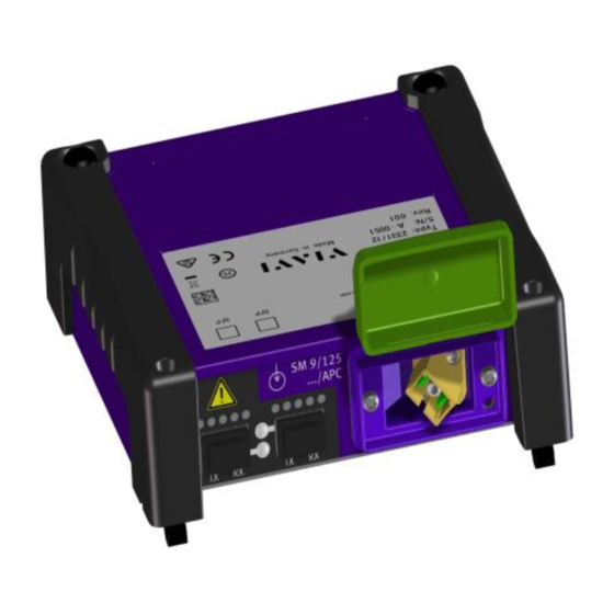
BN 2331/12 Fig. 1 OCC-4056C module The OCC-4056C is VIAVI’s new generation of DWDM analyzer modules. It scans the full C-band wavelength range between 1528 and 1568 nm for commissioning, upgrade, and trouble shooting of DWDM networks. The OCC-4056C offers the functionality and speed of an optical spectrum analyzer in a handheld form at a fraction of the price of an OSA. -
Page 7: Sfp Slots
Chapter 1 Optical Spectrum Measurement Safety information SFP slots The OCC-4056C offers 2 integrated SFP slots for mounting up to 2 SFP transceiver modules or tunable lasers (to be ordered separately). These SFP+ modules can be used as a DWDM stimulus to check DWDM networks together with the DWDM analyzer. -
Page 8: Proper Usage
Chapter 1 Optical Spectrum Measurement Safety information Safety definitions WARNING Indicates a potentially hazardous situation which, if not avoided, could result in death or serious injury. CAUTION Indicates a potentially hazardous situation which, if not avoided, may result in minor or moderate injury. Proper usage This instrument is intended for measurements on optical fiber devices and systems. -
Page 9: Specific Laser Safety
Chapter 1 Optical Spectrum Measurement Safety information Invisible laser radiation Laser radiation can cause irreparable damage to eyes and skin. Follow the laser safety regulations that apply in your area. Take note of the laser classification of the individual test module. WARNING ... -
Page 10: Optical Surfaces
Chapter 1 Optical Spectrum Measurement Safety information Safety instructions for class 1 laser products Invisible laser radiation Class 1 laser products are defined as safe in normal operation under reasonably foreseeable conditions. Although the laser radiation from a class 1 laser product will not CAUTION harm eyes or skin, follow the general laser safety instructions (see General laser safety instructions) to ensure maximum safety... -
Page 11: Start The Occ Application
Chapter 1 Optical Spectrum Measurement Start the OCC application Start the OCC application The fiber to be tested is connected to the optical connector. 1. Select the Fiber Optics button. 2. Select on the Home button. 3. To start the OCC application, select the OCC button. Configuration After connecting the fiber to be tested to the optical connector, you must select the OCC module (see the Base Unit manual). -
Page 12: Manual Configuration
Chapter 1 Optical Spectrum Measurement Configuration In case of any parameter setting the Test Auto WDM softkey appears. Fig. 2 Test Auto WDM softkey (1) Manual Instead of selecting the Test Auto WDM mode the configuration parameters can be set manually. configuration The parameter to be modified must be selected by means of the direction keys... -
Page 13: Acquisition Parameters
Chapter 1 Optical Spectrum Measurement Configuration Acquisition Sweep parameters Continuous There will be a measurement with refreshment of the trace and real time display of results. Single There will be one single measurement and the display of its results. Statistics In this mode, the number of samples concerned by statistics must be entered (next parameter). -
Page 14: Analysis Parameters
Chapter 1 Optical Spectrum Measurement Configuration Analysis parameters Fig. 4 Analysis parameters NOTE Those parameters are only linked to the current active fiber. Channel Grid The grid serves as a detection reference: it must Detection therefore be ITU CWDM or Manual. The choice of grid takes priority over the choice Channel detection. - Page 15 Chapter 1 Optical Spectrum Measurement Configuration NOTE At the end of an acquisition in permanent mode, it is possible to create a grid on the basis of the channels detected. To do this, press the softkey Adopt Grid in the menu.
-
Page 16: Parameters Of Display And Analysis Of The Results
Chapter 1 Optical Spectrum Measurement Configuration Parameters of display and analysis of the results Fig. 5 Display parameters NOTE Those parameters are valid for all traces present on the screen. Grid 1. Go to the Grid line to access the Grid sub-menu. 2. - Page 17 Chapter 1 Optical Spectrum Measurement Configuration None Conventional ITU CWDM Manual – – Editable Editable Grid name – – G.692 ITU standard – – Editable, from 196.10 to First ITU channel 191.20THz, by increments of 50 (with display in THz) –...
- Page 18 Chapter 1 Optical Spectrum Measurement Configuration Fig. 6 Alarm parameters Thresholds can then be set (using the direction keys or numeric keypad), to global level or to the level of each channel: Global alarms Number of channels Yes/No “No” or threshold modifiable from Delta channel power 0.1 to 60 dB (for “No”...
- Page 19 Chapter 1 Optical Spectrum Measurement Configuration Notes Table Here the display can be configured and it can be specified whether or not it is possible to enter a note for each channel (see "Table notes" on page 32): Manual Allows to manually enter a note for each channel in the results table.
-
Page 20: Link Description
Chapter 1 Optical Spectrum Measurement Configuration Link Define the parameters in the Link Description menu and add a comment. Description Fig. 9 Link Description parameters T-BERD/MTS-2000V2, 4000V2, 5800V2 • OCC-4056C • User Manual 2019.04... -
Page 21: File Configuration
Chapter 1 Optical Spectrum Measurement Configuration File In the File Configuration menu, the memory management is set. Configuration Fig. 10 File Configuration parameters T-BERD/MTS-2000V2, 4000V2, 5800V2 • OCC-4056C • User Manual 2019.04... -
Page 22: Acquisition
Chapter 1 Optical Spectrum Measurement Acquisition Acquisition To start a measurement press the key. TART The OCC-4056C will scan over the entire wavelength range and the measurement result will be displayed in graphical and tabular format. Trace display By pressing the button the results window is displayed. -
Page 23: Result Display
Chapter 1 Optical Spectrum Measurement Result display Result display To display the trace only select Trace in the Trace/Table softkey. Overview Fig. 11 Example of result display (Trace only) 1. Filename (only if file was stored) 2. Mini-trace 3. Number of acquisition 4. - Page 24 Chapter 1 Optical Spectrum Measurement Result display The trace represents power (in dBm) as a function of frequency (in THz) or wavelength (in nm). NOTE If several acquisitions are performed, the trace displayed is the one corresponding to the last acquisition. The softkey give access to following functions and menus: Trace Allows to select a trace or a channel (by means of...
-
Page 25: Using The Cursor
Chapter 1 Optical Spectrum Measurement Result display Using the By means of the two cursors A and B following functions are available: – cursor displaying the power level at the cursor position – measuring delta power and total power between two points –... -
Page 26: The Shift Function
Chapter 1 Optical Spectrum Measurement Result display To zoom the y-axis: Zooming the y-axis is independent from the cursor settings. 1. Press the Zoom/Shift softkey and select Zoom. 2. Press the key to reduce or enlarge the y-axis. The Shift The shift functions moves the trace and keeps the cursor on this positions. - Page 27 Chapter 1 Optical Spectrum Measurement Result display Fig. 12 Example of Total Power measurement 3. Pressing the key Total Power A<->B a second time removes the result of the total power measurement. To measure the Delta Power: 1. Set the cursors to the desired positions. At least two detected channels must be between the cursors.
- Page 28 Chapter 1 Optical Spectrum Measurement Result display Channel detection On the trace, some peaks corresponding to noise could be mistaken for channels. It is therefore necessary to fix a power threshold level: only threshold peaks that exceed this threshold will be considered as channels and included in the table of results.
-
Page 29: Multiple Traces (Overlay)
Chapter 1 Optical Spectrum Measurement Result display Multiple traces The Overlay functions allows you to display multiple traces in one view and to compare them. (Overlay) NOTE The Overlay function is not available in Drift mode. To add a new trace: 1. - Page 30 Chapter 1 Optical Spectrum Measurement Result display Adjusting the To compare curves the y axis of the curves can be adjusted by the Y Reset/Y Shift/Y Exact softkey. y axis Press the softkex to select one of he following settings: –...
-
Page 31: Overview
Chapter 1 Optical Spectrum Measurement Table display Table display The table may be displayed in a single line, on half of the screen or the whole screen as a function of the Trace/Table key. Overview Fig. 16 Example of result display (Table only) 1. - Page 32 Chapter 1 Optical Spectrum Measurement Table display 7. Direction: Loc A and Loc B will be used as default. If Origin and End Location are set in the Setup menu, these settings will be used instead. 8. Date and time of measurement 9.
-
Page 33: Channel Sort
Chapter 1 Optical Spectrum Measurement Table display Table statistics When selecting the Statistics measurement mode and multiple acquisitions are performed, statistics are calculated on the results. To display these results in the table: Press the Table Content key, then Statistics and set Stat. to On. Different Statistics keys are available to choose the content of the table display for each channel. - Page 34 Chapter 1 Optical Spectrum Measurement Table display Table notes A note of not more than 40 characters, entered by the user, may be associated with each channel. NOTE Each note is associated with a channel. Consequently, if the channel is deleted, the note the will be deleted too. NOTE These notes appear in the table only if they have been validated in the menu on the...
-
Page 35: Result Colors
Chapter 1 Optical Spectrum Measurement Table display Result colours When Channel Selection is positioned on Grid and the alarm system is activated, measurement results that exceed the defined thresholds are displayed in red, results within the thresholds are displayed in green. (Additionally the icon indicates that at least one result exceeds the threshold and if all results are within the thresholds (no result is in red),... -
Page 36: Trace & Table Display
Chapter 1 Optical Spectrum Measurement Trace & Table display Trace & Table display The Trace & Table display is a combination of the trace only and table only displays. Fig. 18 Example of Delta Power measurement “Result display” on For explanations about the trace functions please see “Table page 21, for explanations about the table functions please see... - Page 37 Chapter 1 Optical Spectrum Measurement Drift measurement The following parameters need to be set for Drift measurements: Sweep Set to Drift. Number of Sweeps Defines the number of sweeps (1 to 10.000). Wait Period Defines the time between the measurements. NOTE Wait period specifies the time between start of one measurement and start of the next measurement and includes the instrument...
- Page 38 Chapter 1 Optical Spectrum Measurement Drift measurement In the Drift display the measurement result is shown in a graphical format (trace over time / scans) and a tabular format. The table shows the following parameters: Wavelen. Level Description Channel Channel Number of the displayed channel.
-
Page 39: Reports
Chapter 1 Optical Spectrum Measurement Reports Reports Fast Report Fast Report generates a report which is stored in file system. Fig. 20 Fast Report (1) To change the Fast Report parameters, select the Results button. Fig. 21 Fast Report parameters T-BERD/MTS-2000V2, 4000V2, 5800V2 •... -
Page 40: File System Report
Chapter 1 Optical Spectrum Measurement Reports File system To view the reports on the file system, select the File button. report Fig. 22 Report from file system T-BERD/MTS-2000V2, 4000V2, 5800V2 • OCC-4056C • User Manual 2019.04... -
Page 41: File Management
Chapter 1 Optical Spectrum Measurement File management File management Storing OSA If Auto store has been selected, then results will be saved automatically. If not, or if you want to save the results under another name, directory measurements etc.: 1. Click on key. -
Page 42: Recycling Information
Hazardous materials VIAVI avoids or uses with care any hazardous or dangerous material in themanufacturing process or the end product. If the use of a dangerous material cannot be avoided, it is identified in product documentation and clearly labeled on the product itself. -
Page 43: Rohs
In the European Union, all equipment purchased from VIAVI after 2005- 08-13 can be returned for disposal at the end of its useful life. Measuring systems affected by this can be recognized by the symbol on the right of a crossed-out trash can and a black bar. - Page 44 Chapter 1 Optical Spectrum Measurement Recycling information T-BERD/MTS-2000V2, 4000V2, 5800V2 • OCC-4056C • User Manual 2019.04...
- Page 45 Chapter 1 Optical Spectrum Measurement T-BERD/MTS-2000V2, 4000V2, 5800V2 • OCC-4056C • User Manual 2019.04...
- Page 46 North America +1 844-468 4284 VIAVI product specifications and descriptions Latin America +1 954 688 5660 in this document are subject to change without China +86 21 6859 5260 notice. Germany +49 7121 86 0 © 2019.04...
- Page 47 Chapter 1 Optical Spectrum Measurement viavisolutions.com User Manual T-BERD/MTS-5800 OCC-4056C, BN 2331/98.21, 2019.04, English T-BERD/MTS-2000V2, 4000V2, 5800V2 • OCC-4056C • User Manual 2019.04...
Need help?
Do you have a question about the T-BERD/MTS- 2000V2 and is the answer not in the manual?
Questions and answers