
Subscribe to Our Youtube Channel
Related Manuals for Skytron ST19 Series


Summary of Contents for Skytron ST19 Series
- Page 1 ST19 SERIES SURGICAL LIGHTS OPERATION / MAINTENANCE / PARTS OWNERS MANUAL REV 4-06...
-
Page 3: Table Of Contents
5-6. ST19S Stand Model Assembly ....................34 5-7. Wall Control Assembly ......................38 Original Printing 7/04 Revised 4/05 Revised 4/06 REV. 4/06 Although current at the time of publication, SKYTRON'S policy of continuous development makes this manual subject to change without notice. - Page 4 Page 2...
-
Page 5: Equipment Labels And Specifications
Page 3 EQUIPMENT LABELS AND SPECIFICATIONS ATTENTION, CONSULT MANUAL FOR FURTHER INSTRUCTIONS. INDICATES SPECIAL USER ATTENTION. AC VOLTAGE FUSE TYPE 3 AMP, SLOW BLOW TYPE CLASS I DEFIBRILLATION PROOF, TYPE B EQUIPMENT- IPX4 RATED. INTERNALLY POWERED EQUIPMENT TYPE B EQUIPMENT FOR DRY LOCATIONS UNIT TO BE USED ONLY IN SPECIFIED ENVIRONMENTAL CONDITIONS TEMPERATURE: 15˚... -
Page 6: Special User Attention
As with the operation of any surgical light, all hospital personnel should be aware that a cer- tain amount of care must be exercised to main- tain patient safety and to keep your SKYTRON WARNING light fixture performing at peak efficiency. - Page 7 Page 5 CAUTION NOTE Use of incompatible cleaning agents To extend the life of the bulb reflector will cause damage to the fixture. Avoid surface, it should not be included in the use of cleaning solutions which normal cleaning. Is should be cleaned contain high concentrations of alcohol, only if absolutely necessary.
-
Page 8: Section I Introduction
360˚ Figure 1-1. Light Fixture Rotation Capabilities The Stellar ST19 series surgical lighting system The standard ST19 series has a lighthead mounted ON/OFF/Intensity control switch and the fixture from SKYTRON features fully adjustable position- ing control for its cool, color-corrected, multiple fuse is located in the Ceiling Cover. -
Page 9: Section Ii Operation
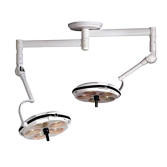
Page 7 SECTION II OPERATION RADIAL ARM ASSEMBLY VERTICAL SUPPORT TUBE VERTICAL SUPPORT TUBE POSITIONING HANDLES BALANCE MECHANISM BALANCE MECHANISM STERILIZABLE POSITIONING HANDLE INTENSITY CONTROL KNOBS STERILIZABLE POSITIONING HANDLE Figure 2-1. Dual Lighthead Fixture NOTE Use the following instructions to operate the light To prolong bulb life, the sof-start bulb fixture: protection circuit will cause a slight delay... - Page 10 Page 8 c. When the surgeon is ready to use the light, install the sterilized center positioning handle using the following procedure. See figure 2-3. Be sure handle is properly secured before using the lighthead. Possible injury to patient or staff could result if a handle is not installed properly.
-
Page 11: Section Iii Maintenance
3-1. General To insure proper operation and to extend the life of •Avoid using excessive amounts of spray cleaners your SKYTRON surgical lighting system, the fol- near top cover vents. Leakage of fluids into the lowing preventive maintenance procedures are interior of lighthead may cause corrosion of electri- recommended. -
Page 12: Bulb Changing
Page 10 3-4. Bulb Changing Since SKYTRON Surgical Lights contain multiple bulbs, it would not normally be necessary to change REFLECTOR a burned out bulb during a surgical procedure. SURFACE BASE To replace a bulb, use the following procedure: WARNING Be sure the power is turned "OFF"... -
Page 13: Preventative Maintenance Procedures
Page 11 3-5. Preventive Maintenance Procedures The following procedures should be done semi- NOTE annually or sooner as needed. To extend the life of the bulb reflector a. Lighthead top cover should be removed and surface, it should not be included in any accumulation of dust or lint removed. -
Page 14: Section Iv Adjustment
Page 12 SECTION IV ADJUSTMENT 4-1. General As a part of normal preventive maintenance, all fixture rotation axes adjustments should be checked and adjusted as necessary. Refer to figure 4-1 for location of desired check or adjustment procedure. A - Lighthead Pitch Axis -------------------------------------------------- paragraph 4-2 B - Lighthead Roll Axis ---------------------------------------------------- paragraph 4-3 C - Vertical Travel Tension ----------------------------------------------- paragraph 4-4 D - Lighthead Horizontal Rotation ------------------------------------- paragraph 4-5... -
Page 15: Lighthead Pitch Adjustment
Page 13 4-2. Lighthead Pitch Adjustment a. Check the pitch axis tension of each lighthead c. Rotate the lighthead until an allen set screw by moving it through its full range of motion. See is visible through the adjustment hole. Loosen the figure 4-2. -
Page 16: Vertical Travel Tension Adjustment
Page 14 4-3. Lighthead Roll Adjustment a. Check the roll axis tension of the lighthead by c. Rotate the yoke until an allen set screw is moving it through its full 360° range of travel. See visible through the adjustment hole and loosen the figure 4-5. -
Page 17: Lighthead Horizontal Rotation Adjustment
Page 15 4-5. Lighthead Horizontal Rotation Adjustment b. The lighthead should move freely yet main- tain its selected position within the range of motion a. Check horizontal rotation axis adjustment by without drifting. If an adjustment is necessary, moving the lighthead through its full range of travel refer to figure 4-8, and proceed as follows: around the Balance Mechanism. - Page 18 Page 16 NOTE CHROME PLUG •Recheck the mounting plate to make sure it is absolutely level. In most PUNCH cases, releveling the mounting plate will solve any drifting problems. •If the lighthead sticks or is difficult to PENCIL MARKS move, before making any adjustments, lubricate the BOM needle bearings with a Teflon type spray lubricant such as TRI-FLOW (available from Richardson-...
-
Page 19: Radial Arm Horizontal Rotation Adjustment
Figure 4-13. Top Cover Removal c. If releveling the mounting plate does not correct the drift, or the Radial Arms are difficult to move, the bearing preload must be adjusted. This requires the use of special tools. Contact your SKYTRON dealer for assistance. - Page 20 Page 18 ST19 Models a. Test bulb voltage at the terminal strip. Turn main power "ON" and set the Dimmer Control to maximum intensity for the test. Output voltage (at the terminals) should be 20V± 0.2V. See figure 4- CIRCUIT BOARD LIGHT TERMINALS TERMINAL STRIP ADJUSTER...
-
Page 21: Service
See figure 4-16. Preventive Maintenance contracts are available through your local SKYTRON representative. WALL CONTROL FRONT PANEL To obtain service instructions, replacement parts, factory service or preventive maintenance con- tracts, contact the SKYTRON representative listed DIMMER CONTROL below. VOLTAGE ADJUSTER DECREASE... -
Page 22: Wiring Diagrams
Page 20... - Page 23 Page 21...
-
Page 24: Section V Replacement Parts
Page 22 SECTION V. REPLACEMENT PARTS 5-1. MOUNTING HUB AND RADIAL ARM ASSEMBLY 011604.01... - Page 25 Page 23 5-1. MOUNTING HUB AND RADIAL ARM ASSEMBLY Item Part No. Description Qty. B4-342-69 COVER, junction box ....................1 B4-030-43 SCREW, phillips, M3x8 ....................3 B9-210-81 BOLT, allen, M5x25 ....................4 B4-342-02 WASHER, flat, M5 ....................... 4 B9-410-25 TRANSFORMER (ST19) ..................... 1 B9-410-26 TRANSFORMER (ST1919) ..................
-
Page 26: Balance Mechanism And Yoke Assemblies
Page 24 5-2. BALANCE MECHANISM AND YOKE ASSEMBLIES 011604.02... - Page 27 Page 25 5-2. BALANCE MECHANISM AND YOKE ASSEMBLIES Item Part No. Description Qty. B4-341-06 COVER, rubber ......................3 B4-242-23 SCREW, phillips, M5x12 ..................... 1 ----- RADIAL ARM ......................1 B4-341-07 VERTICAL SUPPORT TUBE ..................A/R B9-310-06 SCREW, set ......................A/R B3-210-05 BRUSH BLOCK ......................
- Page 28 Page 26 5-2. BALANCE MECHANISM AND YOKE ASSEMBLIES (continued) 011604.02...
- Page 29 Page 27 5-2. BALANCE MECHANISM AND YOKE ASSEMBLIES (continued) Item Part No. Description Qty. B4-342-31 BUSHING ........................1 B4-342-32 SCREW, phillips, M4x4 ....................2 B4-341-12 BEARING BODY ......................1 B4-342-33 BEARING, needle ....................... 1 B4-342-34 WASHER, needle bearing ..................1 B4-342-35 SCREW, phillips, countersunk, M3x10 ...............
-
Page 30: Yoke Assembly
Page 28 5-3. YOKE ASSEMBLY 011604.03... - Page 31 Page 29 5-3. YOKE ASSEMBLY Item Part No. Description Qty. B4-342-17 SCREW, phillips, M3x16 ................... A/R B4-342-16 WASHER, lock, M3 ....................A/R B4-342-36 SCREW, phillips, M3x6 ..................... A/R B4-340-01 CIRCUIT BOARD ...................... A/R B4-342-37 STAND-OFF ......................A/R B4-342-38 SPACER ........................A/R B9-210-28 SCREW, phillips, M4x8 .....................
-
Page 32: Bulb And Reflector Assembly
Page 30 5-4. BULB AND REFLECTOR ASSEMBLY 011604.04... - Page 33 Page 31 5-4. BULB AND REFLECTOR ASSEMBLY Item Part No. Description Qty. B9-410-15 SCREW, phillips, M3x25 ..................... 6 B9-410-16 WASHER, flat, M3 ....................... 6 B1-410-27 HEAT SINK ........................3 B9-410-17 NUT, hex, M4 ......................9 B1-410-28 MOUNT, bulb socket ....................3 B1-410-29 SOCKET, bulb ......................
-
Page 34: Lighthead Assembly
Page 32 5-5. LIGHTHEAD ASSEMBLY 011604.05... - Page 35 Page 33 5-5. LIGHTHEAD ASSEMBLY Item Part No. Description Qty. B4-340-05 TOP COVER, lighthead ....................1 B1-210-34 TERMINAL STRIP ....................... 1 B9-210-35 •SCREW, terminal strip cover ..................2 B1-210-35 •COVER, terminal strip ....................1 B9-210-34 SCREW, terminal strip mounting ................2 B3-220-15 SCREW, bracket mounting, M4x6, phillips ..............
-
Page 36: St19S Stand Model Assembly
Page 34 5-6. ST19S - STAND MODEL ASSEMBLY 011604.06... - Page 37 Page 35 5-6. ST19S - STAND MODEL ASSEMBLY Item Part No. Description Qty. B9-210-28 SCREW, phillips, M4x8 ....................2 B9-210-69 WASHER, flat, M4 ....................... 2 B3-210-04 SLIP RING ........................1 B4-342-52 MOUNT, slip ring ......................1 B4-341-17 SUPPORT ARM ......................1 B3-220-15 SCREW, phillips, M4x6 ....................
- Page 38 Page 36 5-6. ST19S - STAND MODEL ASSEMBLY (continued) 011604.06...
- Page 39 Page 37 5-6. ST19S - STAND MODEL ASSEMBLY (continued) Item Part No. Description Qty. B4-342-63 SCREW, phillips, M4x10 ..................... 4 B5-010-99 WASHER, flat, M4 ....................... 4 B1-010-01 FUSE HOLDER ASSEMBLY ..................2 B9-210-21 FUSE, 250V, 3A ......................2 B4-342-64 NUT, plastic ......................... 1 B4-342-65 GASKET ........................
-
Page 40: Wall Control Assembly
Page 38 5-7. WALL CONTROL ASSEMBLY I T Y I T Y 011604.07... - Page 41 Page 39 5-7. WALL CONTROL ASSEMBLY Item Part No. Description Qty. B9-410-01 WALL CONTROL, ST19WC ..................A/R B9-410-02 WALL CONTROL, ST1919WC ................. A/R B9-310-07 FLANGE, recess mount, single or dual ..............1 B9-210-40 SCREW, flange mounting ................... 8 B9-210-09 COVER, electrical access ................... 1 B9-210-41 SCREW, cover mounting ....................
- Page 44 5000 36th Street S.E. • Grand Rapids, MI 49512 1.800.SKYTRON • 1.616.957.0500 • FAX 1.616.957.5053...
Need help?
Do you have a question about the ST19 Series and is the answer not in the manual?
Questions and answers