Table of Contents
Advertisement
Advertisement
Chapters
Table of Contents
Troubleshooting

Related Manuals for Skytron ELITE 3000


Summary of Contents for Skytron ELITE 3000
- Page 1 ELITE SERIES SURGICAL TABLES OPERATORS MANUAL MODEL ELITE 3000 REV 3-06...
-
Page 2: Table Of Contents
2-3. Emergency Brake Release ......................10 2-4. Positioning ..........................11 SECTION III MAINTENANCE .......................12 3-1. Preventive Maintenance ......................12 3-2 Cleaning Recommendations ......................12 3-3. Service ............................13 REV 3/06 Although current at time of publication, SKYTRON's policy of continuous development makes this manual subject to change without notice. -
Page 3: Equipment Labels And Specificatons
Page 2 EQUIPMENT LABELS AND SPECIFICATIONS FUSE TYPE 10 AMP, FAST ACTING (FA) INDICATES DANGEROUS VOLTAGE, 120 V, 60 Hz CLASS I DEFIBRILLATION PROOF, TYPE B EQUIPMENT- IPX4 RATED. INTERNALLY POWERED EQUIPMENT TYPE B EQUIPMENT PROTECTIVE GROUNDING. IN ORDER TO ENSURE PROPER GROUNDING RELIABILITY, THIS TABLE MUST BE CONNECTED TO A PROPERLY GROUNDED HOSPITAL GRADE OUTLET. -
Page 4: 3000 Series Imaging Table Specifications
Page 3 3000 Series Imaging Table Specifications TOP VIEW 19.7" 65" 82.5" 39" MAX 28" MIN 5.75" 8.25" 40.5" 19" SIDE VIEW END VIEW Electrical Specifications Power requirements 120 VAC, 60Hz, 450 Watts Current Leakage Less than 100 micro amps Power Cord 15 feet w/hospital grade connector ENTELA CERTIFIED... -
Page 5: Special User Attention
Page 4 SPECIAL USER ATTENTION Prior to use, all personnel that may operate this table must be instructed in the correct opera- tional procedures. This table is designed for Do not use worn or damaged accessories, they use by trained and qualified personnel for hu- represent an injury hazard. - Page 6 Page 5 WARNING CAUTION DO NOT unlock brakes when a patient is on the table. An uneven patient MAXIMUM END LOAD 180 POUNDS. weight load may cause instability. During transfer, DO NOT seat the pa- tient at the distal end of the table. Table WARNING stability may be compromised.
-
Page 7: Section I Introduction
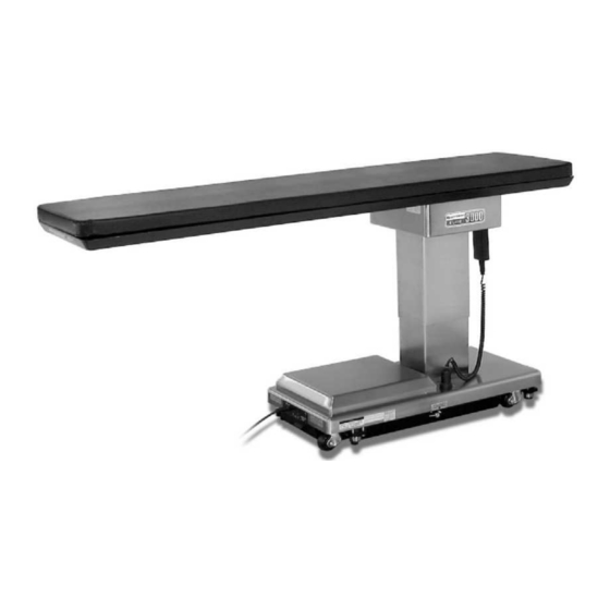
1-1. General 1-2. Power Requirements SKYTRON’s Elite 3000 Series Imaging Tables are The Elite 3000 Surgical Table requires a 120VAC, electro-hydraulically operated. See figure 1-1. 60 Hz electrical power supply. The table is equipped with a 15 foot long power cord with a standard three The electro-hydraulic positioning functions oper- prong, hospital grade plug. -
Page 8: Pendant Control Unit
Page 7 1-4. Floor Lock/Brake System ELECTRICAL POWER ENCLOSURE CORD The floor lock/brake system consists of four self- leveling, hydraulic brake cylinders which raise and MAIN POWER support the table base off from the casters. Press SWITCH COVER the ELEVATION-UP button on the pendant control PLATE to set the table’s brakes. -
Page 9: Section Ii Operation
Page 8 SECTION II OPERATION 2-2. Positioning Functions 2-1. Electrical Power The hand-held pendant control unit (figure 2-2) a. Check to be sure the power cord is plugged activates the following table functions: into 120VAC outlet. WARNING POWER ELITE / 3000 INDICATOR POWER Prior to operating the table, observe all... -
Page 10: Trendelenburg
Page 9 Press the BRAKE-UNLOCK button on the pendant control to release the four self-leveling brake feet in c. Lateral Tilt. To achieve lateral tilt right order to move the table. See figure 2-3. The brake positioning, press the appropriate LATERAL-TILT delay circuit automatically retracts the brake sys- button (figure 2-5). -
Page 11: Return To Level
Page 10 e. Return To Level. To return the table top to a level position, press the RETURN button (figure 2-7). NOTE •The Emergency Brake Release Valve ELITE / 3000 must be closed and tightened (clock- POWER wise) before activating any hydraulic TRENDELENBURG function. -
Page 12: Positioning
Page 11 2-4. Positioning During table set-up and patient positioning, the following items should be observed. The table top is constructed of a radioluscent composite material. Use caution when using ac- SINGLE cessories to protect the table top from damage CARBON FIBER ARMBOARD (2) including nicks or scratches to maintain clear imag-... -
Page 13: Section Iii Maintenance
3-2. Cleaning Recommendations The following preventive maintenance checks and services are recommended to ensure the service- NOTE ability and proper operation of your SKYTRON Surgical Table. Always follow current AORN Journal Guidelines to ensure proper cleaning a. During normal cleaning, a general visual ex- and disinfection procedure. -
Page 14: Service
To obtain service instructions, replacement parts, factory service or preventive maintenance con- Repeat cleaning procedure for all table surfaces tracts, contact the SKYTRON representative listed including the top, sides, elevation column, base and below. all accessories. - Page 15 5000 36th Street S.E., Grand Rapids, MI 49512 1-800-SKYTRON or 1-616-957-0500 • FAX 1-616-957-5053...
- Page 16 ELITE SERIES SURGICAL TABLES MAINTENANCE MANUAL MODEL ELITE 3000 and 3001 Page 37...
- Page 17 3-11. Flexible Hose Identification and Placement ................18 This manual covers the Model 3000 and Model 3001. All reference to top slide pertains to Model 3001 only. Although current at time of publication, SKYTRON's policy of continuous development makes this manual subject to change without notice.
- Page 18 Table of Contents (continued) SECTION IV ELECTRICAL SYSTEM ....................20 4-1. General ............................20 4-2. Components ..........................20 SECTION V ELECTRICAL SYSTEM TROUBLESHOOTING ............. 21 5-1. Troubleshooting Notes........................ 21 5-2. Main Switch..........................21 5-3. Pendant Control .......................... 22 5-4. Relay Box............................ 23 5-5.
- Page 19 • Check All Table Functions • Check Side Rails • Check Velcro • Lubricate Elevation Slider Assembly with SKYTRON Slider Grease P/N D6-010-89 • Lubricate Castors • Check brake pads for wear and inspect brake cylinders for proper operation. • Check Carbon Fiber Top for Damage Only facility-authorized SKYTRON trained, maintenance personnel should troubleshoot the SKYTRON Surgical Table.
- Page 20 EQUIPMENT LABELS AND SPECIFICATIONS INDICATES DANGEROUS VOLTAGE, 120 V, 60 Hz CLASS I DEFIBRILLATION PROOF, TYPE B EQUIPMENT- IPX4 RATED. INTERNALLY POWERED EQUIPMENT TYPE B EQUIPMENT PROTECTIVE GROUNDING. IN ORDER TO ENSURE PROPER GROUNDING RELIABILITY, THIS TABLE MUST BE CONNECTED TO A PROPERLY GROUNDED HOSPITAL GRADE OUTLET.
- Page 21 3001 Series General Purpose Surgical Table Specifications TOP VIEW 30" 13.8" 19.7" 65" 82.5" 20˚ 21.875" 20˚ 20˚ 20˚ 42" MAX 32" MIN 8.25" 19" 40.5" SIDE VIEW END VIEW 3000 Series General Purpose Surgical Table Specifications TOP VIEW 19.7" 65"...
- Page 22 SECTION VI ELECTRICAL SYSTEM ADJUSTMENTS 6-1. Relay Box Adjustments on the relay box circuit board. Turn the adjuster The Relay Box contains variable resistors for ad- clockwise to increase the operating time. Coun- justing the operating timers for the BRAKE SET terclockwise to decrease the operating time.
-
Page 23: Section I Hydraulic System
SECTION I HYDRAULIC SYSTEM 1-1. General b. Motor/Pump Assembly - A positive displace- ment gear type pump provides the necessary oil Electro- Hydraulic System pressure and volume. The hydraulic system (with the exception of the c. Pressure Relief Valve - Provides an alternate hydraulic cylinders and hoses) is contained within oil path when the hydraulic cylinders reach the end the base of the table. -
Page 24: Component Operation
1-2. Component Operation Turning the adjustment nut clockwise increases the amount of oil pressure required to open the a. Motor/Pump Operation valve, and turning it counterclockwise decreases the amount of oil pressure. (See adjustment sec- The motor/pump assembly is a gear type pump tion for specification.) that provides the oil pressure and volume for the entire hydraulic system. -
Page 25: Mini-Valves
c. Mini-Valves The speed controls are always located in the re- The operation of the mini-valves is identical for all turn oil circuit. This prevents uncontrolled move- table functions except the elevation and brake cir- ment of the piston in the slave cylinder due to one cuits. -
Page 26: Mini-Valve Right Port Activated
e. Mini-Valve Right Port Activated f. Mini-Valve Left Port Activated (See figure 1-6) (See figure 1-7.) Slave Cylinder Piston Moves to Left Slave Cylinder Piston Moves to Right Right Mini-Valve Port is Supply Line Left Mini-Valve Port is Supply Line Left Mini-Valve Port is Return Line Right Mini-Valve Port is Return Line INLET... -
Page 27: Hydraulic Cylinders (Slave Cylinders)
The pistons and connection rods are attached to a g. Hydraulic Cylinders (Slave Cylinders) non-movable surface. Therefore, when hydraulic fluid is pumped into one side, the cylinder housing There are several different types of hydraulic cyl- itself moves around its pivot pin causing the table inders used in the table that activate the control top to tilt to one side. - Page 28 4. Lateral Slide Function Cylinder - 3001 Only. This cylinder is also a double action cylinder. It differs from the Trendelenburg cylinder in that the piston is connected to rams which exit from each end of the cylinder tube. The ends of the rams connect to each side of the table top.
-
Page 29: Elevation Cylinder Return Circuit
i. Brake System h. Elevation Cylinder Return Circuit The brake system consists of the following com- A three-way (single check valve type) mini-valve ponents: (figure 1-17) controls both the elevation and return circuits. The elevation circuit operation within the mini-valve is 1. -
Page 30: Emergency Brake Release
The brakes are released by pushing the BRAKE UNLOCK button momentarily. An electronic timer 1-3. Hydraulic Adjustments in the relay box activates the brake function hy- draulic mini-valve and pump/motor. a. Fluid Level. When activated, the return hydraulic circuit oper- The fluid level should be approximately 1/2"... -
Page 31: Pressure Relief Valve
c. Pressure Relief Valve REV TREND TILT LEFT The pressure relief valve is adjusted by turning SLIDE RIGHT the adjustment nut until the desired pressure is SLIDE HEAD reached. TABLE To adjust: DOWN BRAKE TREND 1. Remove the blind cap and attach a hydrau- TILT SLIDE RIGHT... -
Page 32: Section Ii Mechanical Table Adjustments
SECTION II MECHANICAL TABLE ADJUSTMENTS 2-1. Elevation Column Adjustment NOTE CAUTION This adjustment is required only if ex- cessive horizontal table top movement DO NOT OVERTIGHTEN SET occurs, or after replacement of the el- SCREWS. evation column bearing components. This adjustment should only be per- 5. -
Page 33: Section Iii Hydraulic Troubleshooting
SECTION III HYDRAULIC TROUBLESHOOTING 3-1. Precautions Before attempting to troubleshoot any hydraulic Once the problem has been determined, con- problem on the table, please read through the pre- centrate on that particular hydraulic circuit or con- cautions and notes below. trol function. -
Page 34: Elevation Diagnosis Chart
3-3. ELEVATION DIAGNOSIS CHART Reason Problem Pressure Relief Valve Not Set Properly Table will not elevate properly Low on Oil Spool Valve Not Centered Defective Pump Defective Mini-Valve Defective Solenoid or Wiring Defective Relay Box or Pendant Control Leaking Cylinder Hose Uneven Weight Distribution Incorrect Speed Adjustment Table will not descend properly... -
Page 35: Trendelenburg Diagnosis Chart
3-4. TRENDELENBURG DIAGNOSIS CHART Reason Problem Incorrect Speed Adjustment Trendelenburg function moves improperly Spool Valve Not Centered Bad Check Valves Low on Oil Pinched Hose Defective Mini-Valve Pressure Relief Valve Not Set Properly Bad Solenoid or Wiring Defective Relay Box or Pendant Control Defective or Dirty Check Valve Trendelenburg function chatters or loses position Oil Leakage in Circuit... -
Page 36: Lateral Tilt Diagnosis Chart
3-5. LATERAL TILT DIAGNOSIS CHART Reason Problem Incorrect Speed Adjustment Lateral tilt function moves improperly Spool Valve Not Centered or Adjusted Properly Bad Check Valves Low on Oil Pinched Hose Defective Mini-Valve Pressure Relief Valve Not Set Properly Defective Solenoid or Wiring Defective Relay Box or Pendant Control Defective or Dirty Check Valve Lateral tilt function chatters or loses position... -
Page 37: Lateral Slide Diagnosis Chart
3-6. LATERAL SLIDE DIAGNOSIS CHART - 3001 Only Reason Problem Incorrect Speed Adjustment Slide function moves improperly Spool Valve Not Centered or Adjusted Properly Bad Check Valves Low on Oil Pinched Hose Defective Mini-Valve Pressure Relief Valve Not Set Properly Defective Solenoid or Wiring Defective Relay Box or Pendant Control Defective or Dirty Check Valve... -
Page 38: Longitudinal Slide Diagnosis Chart
3-7. LONGITUDINAL SLIDE DIAGNOSIS CHART - 3001 Only Reason Problem Incorrect Speed Adjustment Slide function moves improperly Spool Valve Not Centered or Adjusted Properly Bad Check Valves Low on Oil Pinched Hose Defective Mini-Valve Pressure Relief Valve Not Set Properly Defective Solenoid or Wiring Defective Relay Box or Pendant Control Defective or Dirty Check Valve... -
Page 39: Brake Circuit Diagnosis Chart
3-8. BRAKE CIRCUIT DIAGNOSIS CHART Reason Problem Emergency Brake Release Valve Open or Defec- Brakes will not set properly tive Spool Valve Not Centered Bad Check Valve NOTE Low on Oil If brakes have been released with the Emergency Brake Release Valve, Pressure Relief Valve Not Set Properly brakes will not reset until BRAKE UN- Pinched Hose... -
Page 40: Flexible Hose Identification And Placement
3-11. Flexible Hose Identification and Placement The following figures will show the correct place- ment of the flexible hydraulic hoses used in the table and their respective number codes. LONGITUDINAL SLIDE LATERAL TILT LATERAL SLIDE TREND ELEVATION PLUMBING TERMINAL Figure 3-7, Hydraulic Hose Identification Page 18... - Page 41 SOLENOID PENDANT COIL 120 VAC CONTROL MINI-VALVES PENDANT BASE CONNECTOR RETURN CIRCUIT CN35 RELAY BOX OPTIONAL JOYSTICK CONNECTOR CN10 CAPACITOR CN15 PUMP CN38 ICN1 FOOT MAIN CONTROL POWER CONNECTOR SWITCH POWER CORD Figure 4-1. 3001 Electrical Circuit Block Diagram Page 19...
-
Page 42: Section Iv Electrical System
SECTION IV ELECTRICAL SYSTEM 4-2. Components 4-1. General Refer to figure 4-1 for the relationship of the elec- The complete electrical system (with the excep- trical components. tion of the hand-held pendant control and the re- turn circuit micro-switches) is contained within the a. -
Page 43: Section V Electrical System Troubleshooting
SECTION V ELECTRICAL SYSTEM TROUBLESHOOTING 2. Disconnect connector CN4 from the relay 5-1. Troubleshooting Notes box. See figure 5-1. Leave all other connectors connected. The basic operation of each component will be defined along with a drawing and explanation on WARNING how to check it out. -
Page 44: Pendant Control
If the correct readings are obtained, this part of the circuit is okay and the problem may be the Pendant Control circuit board or the Relay Box. Contact SKYTRON if all tests performed indicate that the problem is located in the Pendant Control. 2 BROWN... -
Page 45: Relay Box
5-4. Relay Box 3. Activate any table function with the Pen- dant Control and using an AC voltmeter, test the The power supply is directly connected to the re- voltage at pins 3 and 4 of CN4 for output to the lay contacts. -
Page 46: Solenoids
1. Plug the table cord into the wall receptacle been conducted and it appears that the Relay Box and turn main switch ON. is faulty, contact SKYTRON. 2. Disconnect the 2 pin connector from the 5-5. Solenoids solenoid in question. See figure 5-7. -
Page 47: Troubleshooting
NOTE d. Test #2 appropriate pendant control The solenoid can be checked out using an button must be pushed during this test. ohm-meter R x 1 scale. The motor will run when this test is performed, and the brake locking sole- 1. - Page 48 e. Test Results: 2. Disconnect the 3 pin connector CN15 at the motor. Leave all other connectors connected. If the solenoid does not check out with the meter, See figure 5-8. it is more than likely defective and must be re- placed.
- Page 49 termine if the capacitor will store a low voltage g. Test Results: charge and most of the time this is adequate. If you do not receive the correct meter readings, 1. Turn the main switch OFF. the motor or wiring is defective. 2.
- Page 50 5-9. Troubleshooting 1. Apply table brakes and (using a level) level the table top using the TRENDELENBURG and If a problem is suspected in the return circuits, dis- LATERAL-TILT function buttons on the pendant connect the connector CN10 from the Relay Box control.
- Page 51 5000 36th Street S.E., Grand Rapids, MI 49512 1-800-SKYTRON or 1-616-957-0500 • FAX 1-616-957-5053 Page 36...
- Page 52 IMAGING TABLE OPERATORS MANUAL 3002 IMPULSE REV 2/06...
- Page 53 SECTION III MAINTENANCE ....................... 15 3-1. Preventive Maintenance ......................15 3-2 Cleaning Recommendations ...................... 15 3-3. Service ............................16 REV 2/06 Although current at time of publication, SKYTRON's policy of continuous development makes this manual subject to change without notice.
-
Page 54: Equipment Labels And Specifications
Page 2 EQUIPMENT LABELS AND SPECIFICATIONS FUSE TYPE 10 AMP, FAST ACTING (FA) INDICATES DANGEROUS VOLTAGE, 120 V, 60 Hz CLASS I DEFIBRILLATION PROOF, TYPE B EQUIPMENT- IPX4 RATED. INTERNALLY POWERED EQUIPMENT TYPE B EQUIPMENT PROTECTIVE GROUNDING. IN ORDER TO ENSURE PROPER GROUNDING RELIABILITY, THIS TABLE MUST BE CONNECTED TO A PROPERLY GROUNDED HOSPITAL GRADE OUTLET. -
Page 55: 3002 Impulse Imaging Table Specifications
Page 3 3002 Impulse Imaging Table Specifications TOP VIEW 30" 19.7" 17.625" 33" 82.5" 21.875" 42" MAX 28" MIN 5.625" 8.125" 40.5" 19" SIDE VIEW END VIEW Electrical Specifications ETL LISTED CONFORMS TO Power requirements 120 VAC, 60Hz, 450 Watts UL STD 60601-1 Current Leakage Less than 100 micro amps... -
Page 56: Special User Attention
Page 4 SPECIAL USER ATTENTION The following precautions should be reviewed Prior to use, all personnel that may operate this by all personnel prior to operating the table. table must be instructed in the correct opera- tional procedures. This table is designed for use by trained and qualified personnel for hu- man medical purposes only. - Page 57 Page 5 NOTE WARNING Activating any function button will acti- DO NOT unlock brakes when a patient vate the brake system. Using the TABLE is on the table. An uneven patient UP function to set the brakes provides weight load may cause instability. a visual assurance that the brakes are locked without altering the table posi- tion, except when emergency brake is...
- Page 58 CAUTION When using spray cleaners DO NOT WARNING spray fluids directly into electrical re- ceptacles or micro switches. SKYTRON assumes no liability for table performance or safety when used in conjunction with accessories designed CAUTION by others. Always consult with...
-
Page 59: Section I Introduction
1-1. General 1-2. Power Requirements The 3002 Impulse Imaging Table requires a SKYTRON’s 3002 Impulse Imaging Table is electro- 120VAC, 60 Hz electrical power supply. The table hydraulically operated. See figure 1-1. is equipped with a 15 foot long removable power The electro-hydraulic positioning functions oper- cord with a three prong, hospital grade plug. -
Page 60: Pendant Control Unit
Page 8 1-3. Pendant Control Unit 1-4. Floor Lock/Brake System The hand-held pendant control unit (figure 1-3) has The floor lock/brake system consists of four self- a non-slip rubber cover which assures a positive leveling, hydraulic brake cylinders which raise and grip during use. -
Page 61: Section Ii Operation
SECTION II OPERATION Page 9 2-1. Electrical Power The pendant control buttons and the green POWER indicator light located in the upper right corner of the pendant control will illuminate. See figure 2-2. WARNING DO NOT use the table in the presence NOTE of FLAMMABLE GASES (Flammable gases are not commonly used in the... -
Page 62: Floor Lock/Brake System
Page 10 a. Floor Lock/Brake System. To activate the P O W E R TRENDELENBURG TRENDELENBURG brakes without affecting table positioning, press LATERAL TILT the ELEVATION-UP button. See figure 2-3. The elevation cylinder will not function until the brakes ELEVATION are completely extended. -
Page 63: Elevation
Page 11 d. Elevation. To raise table top, press the UP To achieve Lateral Top Slide, press the appro- button (figure 2-6.). The table will lift a patient weight of 500 pounds up to a maximum height of 42". To priate SLIDE button (figure 2-8). -
Page 64: Joystick Positioning Control
Page 12 2-3 Joystick Positioning Control The "Joystick" positioning control allows the sur- The joystick is equipped with a safety button on the geon to operate the SLIDE functions of the table to top of the handle. This must be pressed and held move the patient rather than the C-Arm during a down to operate the slide functions of the table. -
Page 65: Emergency Brake Release
Page 13 NOTE WARNING •The Emergency Brake Release Valve must be closed and tightened (counter- Before using the joystick be sure the clockwise) before activating any hy- table is properly locked to the floor. The draulic function. joystick will not automatically lock the brakes. -
Page 66: Positioning
3002 Impulse table. P/N: 2-010-02 RESTRAINT STRAP P/N: 6-010-41-B WARNING SKYTRON assumes no liability for table performance or safety when used in conjunction with accessories designed by others. Always consult with SKYTRON for compatibility issues! 6" ACCESSORY RAIL CLAMP P/N: 6-070-06 Figure 2-16. -
Page 67: Section Iii Maintenance
3-2. Cleaning Recommendations The following preventive maintenance checks and services are recommended to ensure the service- NOTE ability and proper operation of your SKYTRON Imaging Table. Always follow current AORN Journal Guidelines to ensure proper cleaning a. During normal cleaning, a general visual ex- and disinfection procedure. -
Page 68: Service
To obtain service instructions, replacement parts, Repeat cleaning procedure for all table surfaces factory service or preventive maintenance con- including the top, sides, elevation column, base and tracts, contact the SKYTRON representative listed all accessories. below. CAUTION Before replacing pads on the table, make sure the pads and all mating surfaces are completely dry. - Page 69 5000 36th Street S.E., Grand Rapids, MI 49512 1-800-SKYTRON or 1-616-957-0500 • FAX 1-616-957-5053...
- Page 70 Page 31 Item Part No. Description Qty. 3002 SERIES IMAGING TABLE REV 6-05...
- Page 71 Abbreviations As Required ........... A/R Optional ........... opt Serial Number ........S.N. Not Shown..........NS SERIAL NUMBER TAG REV 6-05 Although current at the time of publication, SKYTRON's policy of continuous development makes this manual subject to change without notice.
- Page 72 Page 2 1. Top Plate Assembly ............. Page 4 2. Middle Plate Assembly ..........Page 6 3. Lower Plate & Lateral Tilt Assembly ..... Page 8 4. Elevation Slider Assembly ........Page 12...
- Page 73 Page 3 5. Electrical Components ........Page 16 6. Hydraulic Valves & Fittings ......... Page 20 7. Electro/Minivalve Assembly ......Page 24 8. Base Assembly ........... Page 26...
- Page 74 Page 4 1. TOP PLATE ASSEMBLY 3002.1004.001...
- Page 75 Page 5 1. TOP PLATE ASSEMBLY Item Part No. Description Qty. 1-010-30-P PAD SET, regular ....................... opt 1-010-29-S PAD SET, soft ......................opt 3001T TOP ..........................1 D3-065-02 RAIL, end ........................1 D6-065-01 SCREW, rail ........................ 13 D3-065-03 COLLAR, rail ....................... 13 D3-065-04 RAIL, side ........................
- Page 76 Page 6 2. MIDDLE PLATE ASSEMBLY 3002.1004.002...
- Page 77 Page 7 2. MIDDLE PLATE ASSEMBLY Item Part No. Description Qty. D6-010-83 BOLT, allen, M5 x 30 ....................2 D3-065-10 RETAINER BLOCK ....................... 2 D4-065-03 CYLINDER ASSEMBLY, longitudinal ................2 D4-065-01 FITTING, plumbing ....................... 4 D4-010-08 O-RING, P-7 ....................... A/R OIL LINE (specify function) ..................
- Page 78 Page 8 3. LOWER PLATE AND LATERAL TILT ASSEMBLY 3002.1004.003...
- Page 79 Page 9 3. LOWER PLATE AND LATERAL TILT ASSEMBLY Item Part No. Description Qty. D3-065-27 SLIDE, lateral ....................... 4 D3-066-07 MOUNTING PAD, slide, lateral tilt ................2 D6-010-91 BOLT, allen, M6 x 25 ....................2 D6-010-85 WASHER, M6 ....................... 2 D4-065-05 CYLINDER ASSEMBLY, lateral ...................
- Page 80 Page 10 3. LOWER PLATE AND LATERAL TILT ASSEMBLY (continued) 3002.1004.003...
- Page 81 3. LOWER PLATE AND LATERAL TILT ASSEMBLY (continued) Page 11 Item Part No. Description Qty. D2-060-22 SPACER, mounting plate ..................... 2 D2-060-18 CASTING, lateral tilt pivot .................... 1 D6-060-35 BOLT, allen, M12 x 25 ....................4 D2-060-19 PIN, lateral tilt ....................... 1 D6-060-34 SCREW, set, M8 x 10 ....................
- Page 82 Page 12 4. ELEVATION SLIDER ASSEMBLY 23 20 3002.1004.004...
- Page 83 Page 13 4. ELEVATION SLIDER ASSEMBLY Item Part No. Description Qty. D4-065-23 CYLINDER ASSEMBLY, Trendelenburg ..............1 D4-065-24 •ROD, ball joint, Trendelenburg cylinder ..............1 D4-060-23 •O-RING, P-20 ......................1 D4-065-11 •END CAP, Trendelenburg cylinder ................1 D4-065-12 •BUSHING ........................1 D4-035-29 •O-RING, P-65 ......................
- Page 84 Page 14 4. ELEVATION SLIDER ASSEMBLY (continued) 23 20 3002.1004.004...
- Page 85 Page 15 4. ELEVATION SLIDER ASSEMBLY (continued) Item Part No. Description Qty. D4-066-06 •BACK UP RING ......................1 D4-066-07 •TUBE, primary piston ....................1 D4-066-08 •ROD, primary piston ..................... 1 D4-010-56 •O-RING, P-10A ......................1 D4-066-09 •PISTON, primary ......................1 D4-066-10 •BACK-UP RING ......................
- Page 86 Page 16 5. ELECTRICAL COMPONENTS 3002.1004.005...
- Page 87 •LIGHT, indicator ......................2 D5-066-12 •BUTTON ........................2 D6-066-10 •SCREW, phillips, countersunk, M4 x 20 ..............4 D6-066-11 •LABEL, SKYTRON ....................... 1 D5-066-13 •HOUSING, joystick ....................... 1 D6-066-12 •SCREW, phillips, countersunk, M4 x 7 ................ 3 D6-010-85 •WASHER, flat, M6 ......................4 D6-066-13 •BOLT, allen, M6 x 8 .....................
- Page 88 Page 18 5. ELECTRICAL COMPONENTS (continued) 3002.1004.005...
- Page 89 5. ELECTRICAL COMPONENTS (continued) Page 19 Item Part No. Description Qty. D5-066-34 •STRAIN RELIEF ASSEMBLY ..................1 D5-066-17 •PLATE, joystick bottom ....................1 D5-066-18 •CORD ASSEMBLY, joystick ..................1 D5-066-19 CONNECTOR, 20-pin, female (CN-1) ................1 D5-066-20 RELAY BOX ........................1 D5-066-21 CONNECTOR, 8-pin, female (CN-3) ................
- Page 90 Page 20 6. HYDRAULIC VALVES & FITTINGS 43 44 3002.1004.006...
- Page 91 Page 21 6. HYDRAULIC VALVES & FITTINGS Item Part No. Description Qty. D4-031-23 PRESSURE RELIEF VALVE ..................1 D4-034-20 •CAP, pressure relief valve .................... 1 D4-031-67 •O-RING, P-10 ....................... 1 D6-034-14 •SCREW ........................3 D4-034-21 •BODY, pressure relief valve ..................1 D4-010-51 •O-RING, P-16 .......................
- Page 92 Page 22 6. HYDRAULIC VALVES & FITTINGS (CONTINUED) 43 44 3002.1004.006...
- Page 93 Page 23 6. HYDRAULIC VALVES & FITTINGS (CONTINUED) Item Part No. Description Qty. D6-017-32 •SPACER ........................1 D6-035-06 •SCREW, set, M6 x 25 ....................2 D6-010-41 •NUT, hex, M6 ....................... 2 D6-017-31 •RING, retaining ......................1 D6-010-87 •SCREW, set, M6 x 20 ....................1 D6-017-30 •KNOB ...........................
- Page 94 Page 24 7. ELECTRO / MINI VALVE ASSEMBLY 3002.1004.007...
- Page 95 7. ELECTRO / MINI VALVE ASSEMBLY Page 25 Item Part No. Description Qty. D6-010-65 BOLT, allen, M5 x 35 ..................... 2 D4-010-41 PLUG, cap ........................A/R D4-010-08 O-RING, P-7 ........................ A/R D4-010-42 SPRING, return ......................A/R D4-010-25 VALVE, non-return ...................... A/R D4-010-43 VALVE BLOCK, 4-way ....................
- Page 96 Page 26 8. BASE ASSEMBLY 33 34 3002.1004.008...
- Page 97 8. BASE ASSEMBLY Page 27 Item Part No. Description Qty. D1-066-02 COVER, service access ....................1 D6-050-37 SCREW, phillips, countersunk, M4 x 8 ................ 4 D6-010-51 BOLT, allen, M6 x 10 ..................... 2 D6-010-85 WASHER, flat, M6 ......................2 D1-031-37 FRAME ..........................
- Page 98 Page 28 SPECIAL TOOLS & MAINTENANCE ITEMS Item Part No. Description Qty. 6-050-02 GAUGE, oil pressure ....................A/R D6-010-89 GREASE, slider ....................... 2.8 0z. D6-010-90 OIL, hydraulic ......................Qt. D4-011-02 HOSE, hydraulic, specify length ................A/R D4-011-03 FITTING, hydraulic hose end ..................A/R...
- Page 99 Page 30 5000 36th Street S.E. • Grand Rapids, MI 49512 1.800.SKYTRON • 1.616.957.0500 • FAX 1.616.957.5053...
- Page 100 IMAGING TABLE MAINTENANCE MANUAL 3002 IMPULSE 1-06...
- Page 101 Flexible Hose Identification and Placement ................. 17 SECTION III ELECTRICAL SYSTEM ....................18 3-1. General ............................18 3-2. Components ..........................18 1/06 Although current at time of publication, SKYTRON's policy of continuous development makes this manual subject to change without notice.
- Page 102 TABLE OF CONTENTS (continued) TITLE PAGE SECTION IV ELECTRICAL SYSTEM TROUBLESHOOTING ............20 4-1. Troubleshooting Notes ......................... 20 4-2. Main Switch ..........................20 4-3. Pendant Control ........................... 21 4-4. Joystick Control ........................... 21 4-5. Joystick Interface Box ......................... 22 4-6. Relay Box ............................
- Page 103 • Check brake pads for wear and inspect brake cylinders for proper operation. • Check Carbon Fiber Top for Damage Only facility-authorized SKYTRON trained, maintenance personnel should troubleshoot the SKYTRON Imaging Table. Trouble shooting by unauthorized personnel could result in personal injury or equipment damage. How to contact us: Skytron 5000 36th St.
- Page 104 EQUIPMENT LABELS AND SPECIFICATIONS INDICATES DANGEROUS VOLTAGE, 120 V, 60 Hz CLASS I DEFIBRILLATION PROOF, TYPE B EQUIPMENT- IPX4 RATED. INTERNALLY POWERED EQUIPMENT TYPE B EQUIPMENT PROTECTIVE GROUNDING. IN ORDER TO ENSURE PROPER GROUNDING RELIABILITY, THIS TABLE MUST BE CONNECTED TO A PROPERLY GROUNDED HOSPITAL GRADE OUTLET.
- Page 105 3002 Impulse Imaging Table Specifications TOP VIEW 30" 19.7" 17.625" 33" 82.5" 21.875" 42" MAX 28" MIN 5.625" 8.125" 40.5" 19" SIDE VIEW END VIEW Electrical Specifications ETL LISTED Power requirements 120 VAC, 60Hz, 450 Watts CONFORMS TO UL STD 60801-1 Current Leakage Less than 100 micro amps CERTIFIED TO...
-
Page 106: Section I Hydraulic System
Page 1 SECTION I HYDRAULIC SYSTEM 1-1. General b. Motor/Pump Assemblies - Positive displace- ment gear type pumps provide the necessary oil The hydraulic system (with the exception of the hy- pressure and volume. draulic cylinders and hoses) is contained within the c. -
Page 107: Component Operation
Page 2 1-2. Component Operation a. Motor/Pump Operation PRESSURE RELIEF ADJUSTMENT NUT The motor/pump assemblies are gear type pumps that provide the oil pressure and volume for the en- SPRING tire hydraulic system. Each pump has an inlet side LOADED and an outlet side. -
Page 108: Mini-Valves
Page 3 c. Mini-Valves restricting the return oil. If the pump puts out more The operation of the mini-valves is identical for all volume to a slave cylinder than is allowed by the table functions except the elevation and brake cir- speed control, the pressure relief valve opens and cuits. - Page 109 Page 4 Mini-Valve Left Port Activated Mini-Valve Right Port Activated (See figure 1-7.) (See figure 1-6) Left Mini-Valve Port is Supply Line Right Mini-Valve Port is Supply Line Right Mini-Valve Port is Return Line Left Mini-Valve Port is Return Line INLET OUTLET INLET...
-
Page 110: Hydraulic Cylinders (Slave Cylinders)
Page 5 d. Hydraulic Cylinders (Slave Cylinders) There are several different types of hydraulic cyl- The pistons and connection rods are attached to a inders used in the table that activate the control non-movable surface. Therefore, when hydraulic functions. With the exception of the elevation and fluid is pumped into one side, the cylinder housing brake cylinders, all operate basically the same way. - Page 111 Page 6 4. Lateral Slide Function Cylinder - This cylin- der is also a double action cylinder. It differs from the Trendelenburg cylinder in that the piston is con- ELEVATION CYLINDER nected to rams which exit from each end of the cylinder tube.
-
Page 112: Elevation Cylinder Return Circuit
Page 7 e. Elevation Cylinder Return Circuit f. Brake System A three-way (single check valve type) mini-valve The brake system consists of the following com- controls both the elevation and return circuits. The ponents: (figure 1-15) elevation circuit operation within the mini-valve is identical to the operation of the four-way valves 1. -
Page 113: Emergency Brake Release
RESERVOIR 050305.05 Figure 1-17. EMERGENCY BRAKE RELEASE The type of oil that should be used is SKYTRON 050305.04 P/N. D6-010-90 or equivalent. This is a very high Figure 1-16. quality hydraulic oil. The table requires approxi- mately two quarts of oil to operate properly. Exer-... -
Page 114: Pressure Relief Valve
Page 9 c. Pressure Relief Valve TABLE DOWN The pressure relief valve is adjusted by turning the REVERSE TREND. TRENDELENBURG adjustment nut until the desired pressure is TILT LEFT reached. TILT RIGHT SLIDE RIGHT SLIDE LEFT To adjust: SLIDE HEAD SLIDE FOOT 1. -
Page 115: Section Ii Hydraulic Troubleshooting
Page 10 SECTION II HYDRAULIC TROUBLESHOOTING 2-1. Precautions Before attempting to troubleshoot any hydraulic Listed below are the hydraulic components that problem on the table, please read through the pre- are common with all hydraulic circuits. If there is a problem with any of them, it could affect all control cautions and notes below. -
Page 116: Elevation Diagnosis Chart
Page 11 2-3. ELEVATION DIAGNOSIS CHART Reason Problem Uneven Weight Distribution Table will not elevate properly Pressure Relief Valve Not Set Properly Low on Oil Spool Valve Not Centered Defective Pump Defective Mini-Valve Defective Solenoid or Wiring Defective Relay Box or Pendant Control Leaking Cylinder Hose Uneven Weight Distribution Table will not descend properly... -
Page 117: Trendelenburg Diagnosis Chart
Page 12 2-4. TRENDELENBURG DIAGNOSIS CHART Problem Reason Trendelenburg function moves improperly Uneven Weight Distribution Incorrect Speed Adjustment Spool Valve Not Centered Bad Check Valves Low on Oil Pinched Hose Defective Mini-Valve Pressure Relief Valve Not Set Properly Bad Solenoid or Wiring Defective Relay Box or Pendant Control Trendelenburg function chatters or loses position Defective or Dirty Check Valve... -
Page 118: Lateral Tilt Diagnosis Chart
Page 13 2-5. LATERAL TILT DIAGNOSIS CHART Problem Reason Lateral tilt function moves improperly Excessive Patient Weight Incorrect Speed Adjustment Spool Valve Not Centered or Adjusted Properly Bad Check Valves Low on Oil Pinched Hose Defective Mini-Valve Pressure Relief Valve Not Set Properly Defective Solenoid or Wiring Defective Relay Box or Pendant Control Lateral tilt function chatters or loses position... -
Page 119: Lateral Slide Diagnosis Chart
Page 14 2-6. LATERAL SLIDE DIAGNOSIS CHART Problem Reason Slide function moves improperly Excessive Patient Weight Incorrect Speed Adjustment Spool Valve Not Centered or Adjusted Properly Bad Check Valves Low on Oil Pinched Hose Defective Mini-Valve Pressure Relief Valve Not Set Properly Defective Solenoid or Wiring Defective Relay Box or Pendant Control Slide function chatters or loses position... -
Page 120: Longitudinal Slide Diagnosis Chart
Page 15 2-7. LONGITUDINAL SLIDE DIAGNOSIS CHART Reason Problem Excessive Patient Weight Slide function moves improperly Incorrect Speed Adjustment Spool Valve Not Centered or Adjusted Properly Bad Check Valves Low on Oil Pinched Hose Defective Mini-Valve Pressure Relief Valve Not Set Properly Defective Solenoid or Wiring Defective Relay Box or Pendant Control Defective or Dirty Check Valve... -
Page 121: Brake Circuit Diagnosis Chart
Page 16 2-8. BRAKE CIRCUIT DIAGNOSIS CHART Problem Reason Brakes will not set properly Emergency Brake Release Valve Open or Defec- tive Spool Valve Not Centered NOTE Bad Check Valve If brakes have been released with the Low on Oil Emergency Brake Release Valve, Pressure Relief Valve Not Set Properly brakes will not reset until BRAKE UN-... -
Page 122: Flexible Hose Identification And Placement
Page 17 2-9. Flexible Hose Identification and Placement The following figures will show the correct place- ment of the flexible hydraulic hoses used in the table and their respective number codes. LATERAL SLIDE LATERAL TILT TRENDELENBURG LONGITUDINAL SLIDE (4) BRAKE ASSEMBLIES ELEVATION PLUMBING 050305.11... -
Page 123: Section Iii Electrical System
Page 18 SECTION III ELECTRICAL SYSTEM 3-2. Components 3-1. General Refer to figure 3-1 for the relationship of the elec- The complete electrical system (with the excep- trical components. tion of the hand-held pendant control and the re- turn circuit micro-switches) is contained within the base of the table. - Page 124 Page 19 SOLENOID COIL 120 VAC MINI-VALVES JOYSTICK BASE CONNECTOR IFCN3 PENDANT IFCN2 BASE CONNECTOR PENDANT JOYSTICK CONTROL INTERFACE RELAY BOX RETURN IFCN1 CIRCUIT JOYSTICK CN10 CONTROL PUMP PUMP (high speed) CAPACITOR CAPACITOR MAIN POWER SWITCH TWIST-LOCK POWER CORD 050305.26 Figure 3-1.
-
Page 125: Section Iv Electrical System Troubleshooting
Page 20 SECTION IV ELECTRICAL SYSTEM TROUBLESHOOTING 4-1. Troubleshooting Notes 2. Disconnect connector CN4 from the relay The basic operation of each component will be box. See figure 4-1. Leave all other connectors defined along with a drawing and explanation on connected. -
Page 126: Pendant Control
If the correct readings are obtained, this part of the circuit is okay and the problem may be the Pendant Control circuit board or the Relay Box. Contact SKYTRON if all tests performed indicate that the problem is located in the Pendant Control. BASE END PENDANT END 4-4. -
Page 127: Joystick Interface Box
Page 22 4-5. Joystick Interface Box b. Disconnect the cord connector and using an The Joystick Interface Box contains the relay con- ohmmeter, test the continuity between the connec- tacts and circuitry which when activated by the tor and the table base connector. See figure 4-5. joystick, sends the appropriate signals to the relay box for top slide operation as well as the standard and high speed pump activation. -
Page 128: Relay Box
Page 23 trols the relays by the use of the hand-held pen- WARNING dant control buttons. Basically the relays enable a 5-6 volt potential to control the 120 volt circuit. Line voltage (120 VAC) will be mea- sured in this test. Do not touch uninsu- lated connector pins or meter test leads. - Page 129 If all tests have tons measure the voltage for the corresponding been conducted and it appears that the Relay Box connector pins with an AC voltmeter. See figure 4- is faulty, contact SKYTRON. 11. Meter should read 120VAC.
-
Page 130: Solenoids
Page 25 4-7. Solenoids a. Solenoid Test The solenoids are energized by 120 volt potential The resistance of the solenoid coil can be that is controlled by the relay box. The solenoid checked out using an ohm-meter R x 1 scale. windings are protected from excessive heat by an internal thermal fuse that will open after 1. -
Page 131: Motor/Pump Assemblies
Page 26 4-8. Motor/Pump Assemblies 3. Activate a table function. Use a voltmeter capable of measuring 120 VAC and measure the The electric motors are capacitor start type with a following connector pins in connector. See figure rating of 120 VAC, 200 watts. The field windings are 4-14. - Page 132 Page 27 e. Test Results: The meter should move up scale and then back down to infinity. This would indicate that the ca- pacitor is storing an electrical charge. NOTE The capacitor may have to be dis- charged first (by shorting pins 2 and 3 together) before you will be able to see the ohmmeter needle swing up the scale.
-
Page 133: Return-To-Level Micro-Switches
Page 28 4-10. Troubleshooting 4-9. Return-to-Level Micro-Switches. If a problem is suspected in the return circuits, dis- The return-to-level feature is activated by a single connect the connector CN10 from the Relay Box button on the pendant control and automatically lev- to eliminate the circuits. - Page 134 Page 29 b. Switch Adjustment. If proper readings are not obtained during test or if RETAINING RETAINING table does not properly return to level, use the fol- SCREW SCREW lowing procedure to adjust the switches. 1. Apply table brakes and (using a level) level the table top using the TRENDELENBURG and LATERAL-TILT function buttons on the pendant control.
- Page 135 5000 36th Street S.E., Grand Rapids, MI 49512 1-800-SKYTRON or 1-616-957-0500 • FAX 1-616-957-5053...
Need help?
Do you have a question about the ELITE 3000 and is the answer not in the manual?
Questions and answers