
Related Manuals for Skytron ELITE Series


Summary of Contents for Skytron ELITE Series
- Page 1 ELITE SERIES SURGICAL TABLES OPERATORS MANUAL MODEL ELITE 3500 INCLUDING BATTERY MODELS...
- Page 3 SKYTRON STANDARD LIMITED WARRANTY SKYTRON, a Division of the KMW Group, Inc. (SKYTRON) warrants all new products sold by it directly or through a dealer or other authorized representative, with exception to replacement parts, spares, bulbs (surgical lights), pads, and accessory items (surgical tables) to be free from defects in material or workmanship, under normal use and service, for a period of two (2) years.
-
Page 5: Table Of Contents
TABLE OF CONTENTS Title Page EQUIPMENT LABELS AND SPECIFICATIONS ..................2 3500 Series General Purpose Surgical Table Specifications ..............3 SPECIAL USER ATTENTION ........................ 4 SECTION I INTRODUCTION ......................... 7 1-1. General ............................7 1-2. Power Requirements ........................7 1-3. Pendant Control Unit ........................8 1-4. -
Page 6: Equipment Labels And Specifications
EQUIPMENT LABELS AND SPECIFICATIONS FUSE TYPE 10 AMP, FAST ACTING (FA) INDICATES DANGEROUS VOLTAGE, 120 V, 60 Hz CLASS I DEFIBRILLATION PROOF, TYPE B EQUIPMENT- IPX4 RATED. INTERNALLY POWERED EQUIPMENT TYPE B EQUIPMENT PROTECTIVE GROUNDING. IN ORDER TO ENSURE PROPER GROUNDING RELIABILITY, THIS TABLE MUST BE CONNECTED TO A PROPERLY GROUNDED HOSPITAL GRADE OUTLET. -
Page 7: 3500 Series General Purpose Surgical Table Specifications
3500 Series General Purpose Surgical Table Specifications 9-1/2" 18-1/2" 25" 23" TOP VIEW 60˚ 79" 21-3/4" 6" 19-3/4" 90˚ 26-45"* 6" 8-1/2" 19" 40-1/2" SIDE VIEW END VIEW Electrical Specifications Power requirements 120 VAC, 60Hz, 450 Watts Current Leakage Less than 100 micro amps Power Cord 15 feet w/hospital grade connector (removeable on battery model) -
Page 8: Special User Attention
SPECIAL USER ATTENTION WARNING The extreme positioning capabilities of the 3500 Risk of electrical shock. Make sure Series Table requires special attention for possible power cord is disconnected prior to ac- interference points when using multiple function cessing fuses. positioning. As with the operation of any surgical table, a certain amount of care should be exercised NOTE to position the patient safely. - Page 9 NOTE WARNING The Emergency Brake Release Valve To maximize patient safety, utilize must be closed and tightened (clock- proper restraint methods during extreme wise) before activating any function. Trendelenburg positioning. •If the Emergency Brake Release Valve has been operated, the UNLOCK but- WARNING ton on the pendant control will have to To maximize patient safety, utilize...
- Page 10 AC 120V mode. WARNING Certain accessories may limit weight NOTE capacities. Check with your SKYTRON In battery mode, only the red indicator representative. light will be on. In AC 120V mode, both the green indicator light and red indica- NOTE tor light will be on.
-
Page 11: Section I Introduction
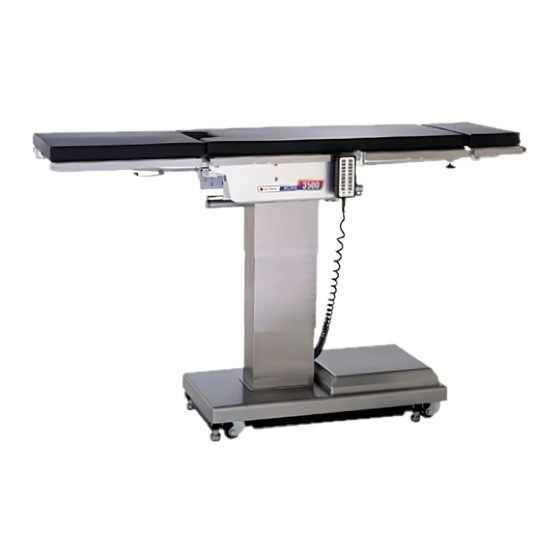
POWER SWITCH Figure 1-1. Elite 3500 1-1. General SKYTRON’s Elite 3500 Series Surgical Tables are electrical enclosure on the front edge of the base. electro-hydraulically operated, general purpose sur- See figure 1-2. The main power ON/OFF switch is gical tables. See figure 1-1. -
Page 12: Pendant Control Unit
1-3. Pendant Control Unit 1-4. Floor Lock/Brake System The hand-held pendant control unit (figure 1-3) has The floor lock/brake system consists of four self- a non-slip rubber cover which assures a positive leveling, hydraulic brake cylinders which raise and grip during use. A spring clip hanger located on the support the table base off from the casters. -
Page 13: Section Ii Line Power Model Operation
SECTION II LINE POWER MODEL OPERATION 2-1. Electrical Power REVERSE TRENDELENBURG TRENDELENBURG a. Check to be sure the power cord is plugged LATERAL LATERAL TILT RIGHT into a properly grounded, Hospital Grade, 120VAC TILT LEFT outlet. Make sure the power cord is routed so as to BACK UP BACK DOWN prevent it from being in the way of the operating... -
Page 14: Trendelenburg
b. Trendelenburg. To place the surgical table in a trendelenburg (head down) position, press the TREND button (figure 2-4). Trendelenburg posi- TILT tioning of up to 25° may be obtained. To place the TILT LEFT table in a reverse trendelenburg (head up) position, RIGHT press the REV TREND button. -
Page 15: Elevation
e. Elevation. To raise table top, press the TABLE-UP button (figure 2-7.). The table will lift a SLIDE SLIDE FOOT patient weight of 500 pounds up to a maximum HEAD height of 45". To lower the table top, press the TABLE-DOWN button. -
Page 16: Flex Positioning
h. Flex Positioning. To place the table top in j. Return To Level. To return the table top to a a flex position from horizontal, press the FLEX level position, press the RETURN button (figure 2- button (figure 2-10). To return the table top to a 12). -
Page 17: Head Section
2-4. Head Section WARNING a. A quick release positioning bar located under In the unlikely event that a procedure and to the front of the head section (figure 2-14) is requires the reversal of the patient on used to raise or lower the head section. Pull the the table top with the head section at- release bar toward the head end to allow the tached to the leg section, the patient... -
Page 18: Section Iii Battery Model Operation
SECTION III BATTERY MODEL OPERATION 3-1. Battery Model Table, AC 120V Operation •If the Emergency Brake Release Valve has been operated, the BRAKE UN- LOCK button on the pendant control will a. Be sure the power cord is plugged into a properly grounded, Hospital Grade, 120VAC out- have to be pressed before brakes will let. -
Page 19: Automatic Shut-Off
3-3. Automatic Shut-Off c. A full battery charge will last approximately 2 weeks under normal operating conditions. How- a. To prevent unnecessary discharge of the ever, it is recommended to charge the batteries at the end of each week to establish a normal routine battery, a timer is built into the battery circuit. -
Page 20: Positioning Functions
3-6. Positioning Functions Press the BRAKE-UNLOCK button on the pendant The hand-held pendant control unit (figure 3-5) control to release the four self-leveling brake feet in activates the following table functions: order to move the table. See figure 3-6. The brake delay circuit automatically retracts the brake sys- AC120V POWER ON REVERSE... -
Page 21: Lateral Tilt
c. Lateral Tilt. To achieve lateral tilt right (as ELITE/ 3500B viewed from the head end of the table), press the RETURN/CTR POWER BATT REV. TREND TREND BACK TILT-RIGHT button (figure 3-8). Tilt of up to 20° TILT TILT LEFT RIGHT BACK BACK... -
Page 22: Top Slide
ELITE/ 3500B RETURN/CTR POWER BATT REV. TREND TREND TILT TILT f. Top Slide. To move the table top toward the LEFT RIGHT BACK BACK DOWN TABLE TABLE head end, press the SLIDE HEAD button. From DOWN LEG DOWN LEG UP SLIDE SLIDE HEAD... -
Page 23: Kidney Lift
3-7. Emergency Brake Release. i. Kidney Lift. To raise the built-in kidney lift, press the KIDNEY-UP button (figure 3-14). Up to In case of a power failure or an electrical problem 5-1/2 inches of lift can be achieved. Press the within the table, the emergency brake release KIDNEY -DOWN button to lower the kidney lift. -
Page 24: Head Section
3-8. Head Section a. A quick release positioning bar located under WARNING and to the front of the head section (figure 3-17) is In the unlikely event that a procedure used to raise or lower the head section. Pull the requires the reversal of the patient on release bar toward the head end to allow the the table top with the head section at-... -
Page 25: Positioning
3-10. Positioning The use of certain optional accessories available from SKYTRON further extend the positioning capabilities of the 3500 Series Tables. Refer to the following "Positioning Guidelines" or contact your SKYTRON representative for further details. - Page 26 3500 Series Patient Positioning Guidelines Upper Body Imaging Accessories: 10” Foot Extension Lower Body Imaging Accessories: 10” Foot Extension and 2” Pad, Standard Armboard and 2” Pad. and 2” Pad, Snap Strap, Multi-Task Armboard with Pad. Endovascular (with 48” Leg Extension) Urology Accessories: Ankl-Lock Stirrups, Uro Catcher, Uro Accessories: 48”...
- Page 27 3500 Series Patient Positioning Guidelines Neuro (neck) Accessories: 10” Foot Extension and 2” Pad, Neuro (lumbar) Accessories: Snap Strap, General Snap Strap, Multi-Task Armboard with Pad. Purpose Head Support, Multi-Task Armboard with Pad. Shoulder Arthroscopy Accessories: 10” Foot Extension Lumbar Accessories: Knee Rest and 4” Pad, Snap Strap, and 2”...
-
Page 28: Section Iv Maintenance
The following preventive maintenance checks and disposable materials following appropriate biohaz- services are recommended to ensure the service- ability and proper operation of your SKYTRON ard waste disposal procedures. Surgical Table. Remove all table pads and place them on a flat surface for cleaning. -
Page 29: Service
Service instructions and parts are available from SKYTRON. To obtain service instructions, replacement parts, factory service or preventive maintenance con- tracts, contact the SKYTRON representative listed below. Or contact: SKYTRON 5000 - 36th Street S.E. - Page 32 5000 36th Street S.E., Grand Rapids, MI 49512 1-800-SKYTRON or 1-616-957-0500 • FAX 1-616-957-5053...
Need help?
Do you have a question about the ELITE Series and is the answer not in the manual?
Questions and answers