
Related Manuals for ADLINK Technology cPCI-6940 Series


Summary of Contents for ADLINK Technology cPCI-6940 Series
- Page 1 Series Server-grade 6U CompactPCI® Intel® Xeon® D-1500 Processor Blade User’s Manual Manual Rev.: Revision Date: March 30, 2020 Part No: 50-15106-2010 Leading EDGE COMPUTING...
- Page 2 Leading EDGE COMPUTING Revision History Revision Release Date Description of Change(s) 2018-02-01 Initial release 2020-03-30 Update memory installation instructions Revision History...
-
Page 3: Preface
Preface Copyright © 2018-2020 ADLINK Technology Inc. This document contains proprietary information protected by copy- right. All rights are reserved. No part of this manual may be repro- duced by any mechanical, electronic, or other means in any form without prior written permission of the manufacturer. - Page 4 Leading EDGE COMPUTING California Proposition 65 Warning WARNING: This product can expose you to chemicals including acrylamide, arsenic, benzene, cadmium, Tris(1,3-dichloro-2-propyl)phosphate (TDCPP), 1,4-Diox- ane, formaldehyde, lead, DEHP, styrene, DINP, BBP, PVC, and vinyl materials, which are known to the State of California to cause cancer, and acrylamide, benzene, cadmium, lead, mercury, phthalates, toluene, DEHP, DIDP, DnHP, DBP, BBP, PVC, and vinyl materials, which are known to the State of California to cause...
-
Page 5: Table Of Contents
Processors................. 13 Chipset................15 Graphics ................15 XMC................... 15 Intel® Turbo Boost Technology ......... 15 Intel® Hyper-Threading Technology........16 Trusted Platform Module ........... 16 Battery ................17 4 Board Interfaces ............... 19 cPCI-6940 Series Board Layout ........19 Table of Contents... - Page 6 Leading EDGE COMPUTING cPCI-6940 Series Assembly Layout ........21 cPCI-6940 Series Faceplate ..........24 Connector Pin Assignments..........27 Switches and Buttons ............40 5 Getting Started ..............45 CPU and Heatsink ............. 45 Memory Module Installation ..........46 2.5" SATA Drive Installation..........48 Installing the cPCI-6940 to the Chassis ......
- Page 7 cPCI-6940 8.4.5 PCH Configuration............93 Security Setup ..............99 Boot Settings ..............103 Save & Exit Menu ............104 9 Checkpoints & Beep Codes .......... 107 Checkpoint Ranges ............107 Standard Checkpoints ............. 107 OEM-Reserved Checkpoint Ranges........ 116 10 IPMI User Guide.............. 117 10.1 Introduction ..............
- Page 8 Leading EDGE COMPUTING This page intentionally left blank. viii Table of Contents...
-
Page 9: List Of Figures
List of Figures Figure 2-1: cPCI-6940 Processor Blade Functional Block Diagram .. 8 Figure 4-1: cPCI-6940 Series Board Layout - Component Side ..19 Figure 4-2: cPCI-6940 Series Board Layout - Solder Side ....20 Figure 4-3: cPCI-6940 Assembly Layout ......... 21 Figure 4-4: cPCI-6940DH Assembly Layout ........ - Page 10 Leading EDGE COMPUTING This page intentionally left blank. List of Figures...
-
Page 11: List Of Tables
cPCI-6940 List of Tables Table 2-1: cPCI-6940 Processor Blade Specifications ..... 5 Table 2-2: cPCI-6940 I/O Connectivity ..........9 Table 4-1: cPCI-6940 Faceplate System LED Descriptions ... 25 Table 4-2: Faceplate COM Pin Definitions........27 Table 4-3: COM RJ-45 to DB-9 Cable Pin Definitions ....27 Table 4-4: DisplayPort Connector Pin Definition...... - Page 12 Leading EDGE COMPUTING This page intentionally left blank. List of Tables...
-
Page 13: Introduction
Introduction 1.1 Overview The ADLINK cPCI-6940 Series is a 6U CompactPCI® processor blade with Intel® Xeon® Processor D-1500 series. Intel® Xeon® Processor D-1500 family is based on 14nm silicon technology and integrates the CPU and chipset in a single system-on–chip (SoC). - Page 14 Moreover, the cPCI-6940 supports remote manageability by IPMI for system health monitoring over the Internet. The cPCI-6940 Series offers powerful computing power based on the low power, high density Intel® Xeon® Processor D-1500 family, and is an ideal solution for military, aerospace and other robust computing applications that require highest computing power in a rugged, reliable CompactPCI system.
-
Page 15: Features
cPCI-6940 1.2 Features 6U CompactPCI blade in 4/8HP width form factor 14nm uFC-BGA Intel® Xeon® Processor D-1500 family Intel® Xeon® processor D-1577, 16-core, 24M Cache, 1.30/2.1 GHz, 45W TDP Intel® Xeon® processor D-1559, 12-core, 18M Cache, 1.50/2.1 GHz, 45W TDP, -40°C to 85°C Intel®... -
Page 16: Package Contents
Please obtain authorization before returning any product to ADLINK. The packing contents of cPCI-6940 Series non-standard configurations will vary depending on customer requests. CPU module... -
Page 17: Specifications
cPCI-6940 Specifications 2.1 Processor Blade Specifications CompactPCI® • PICMG® 2.0 CompactPCI® Rev. 3.0 Standards • PICMG® 2.1 Hot Swap Specification Rev. 2.0 • PICMG® 2.9 System Management Rev. 1.0 • PICMG® 2.16 Packet Switching Backplane Rev. 1.0 Mechanical • Standard 6U CompactPCI® •... - Page 18 Leading EDGE COMPUTING Graphics • Independent PCIe x8 AMD Radeon™ E8860 FCBGA embedded GPU, 128-bit wide, 2048MB, configuration type GDDR5, 72Gbps, 625 MHz graphics clock, DirectX 11.1, Open GL 4.2, Open CL 1.2 • Supports up to 4 independent displays •...
- Page 19 cPCI-6940 Faceplate I/O cPCI-6940 (4HP) • 1x RJ-45 serial port • 1x DisplayPort • 1x VGA port • 2x 10/100/1000BASE-T Ethernet ports • 2x USB 3.0 ports cPCI-6940DH (8HP) • 1x RJ-45 serial port • 1x DisplayPort • 1x VGA port •...
-
Page 20: Block Diagrams
Leading EDGE COMPUTING 2.2 Block Diagrams cPCI-6940 Processor Blade Front Panel COM1 SO-CDIMM, max. 16GB GbE 3/4 USB 3.0 Audio SO-CDIMM, max. 16GB USB 3.0 82580 2.5” HDD Soldered w/ECC, max. 16GB B2B DB-6940 PCIe x1 DDR4-2133 USB 2.0 SATA0 Intel®... -
Page 21: I/O Connectivity Table
cPCI-6940 2.3 I/O Connectivity Table Function cPCI-6940 (4HP) cPCI-6940DX (8HP) cPCI-6940DH (8HP) Faceplate Onboard Faceplate Onboard Faceplate Onboard Gigabit Ethernet Y x2 Y x2 Y x2 Y (RJ-45) Y (RJ-45) Y (RJ-45) USB3.0 Y x2 Y x2 Y x2 USB 2.0 DisplayPort Y x1 Y x1... -
Page 22: Power Requirements
Leading EDGE COMPUTING 2.4 Power Requirements In order to guarantee a stable functionality of the system, it is rec- ommended to provide more power than the system requires. An industrial power supply unit should be able to provide at least twice as much power as the entire system requires of each voltage. - Page 23 Power Consumption This section provides information on the power consumption of cPCI-6940 Series when using Intel® Xeon® Processor D-1500 fam- ily with 16GB DDR4-2133 ECC soldered memory and two 4GB DDR4-2133 ECC socket memory module. Storage device is used with ADLINK ASD26-MLC64G-CT 64GB SATA SSD.
- Page 24 Leading EDGE COMPUTING This page intentionally left blank. Specifications...
-
Page 25: Functional Description
Functional Description The following sections describe the cPCI-6940 Series features and functions. 3.1 Processors The Intel® Xeon® Processor D-1500 family the first Intel® Xeon® SoC based on 14nm silicon technology. The Intel® Xeon® proces- sor D-1500 product family is the first offering of a line of proces- sors that will address a broad rand of low-power, high-density application needs. - Page 26 Leading EDGE COMPUTING Supported Technologies Features D-1577 D-1559 D-1539 Intel® Virtualization Technology for Directed I/O (Intel® VT-d) Intel® Virtualization Technology (Intel® VT-x) Intel® VT-x with Extended Page Tables (EPT) Intel® Hyper-Threading Technology Intel® 64 Architecture Execute Disable Bit — Intel® Turbo Boost Technology Intel®...
-
Page 27: Chipset
cPCI-6940 3.2 Chipset The Intel® Xeon® Processor D-1500 family integrates a platform controller hub (PCH) in the SoC 3.3 Graphics The cPCI-6940 is equipped with the AMD Radeon™ E8860 embedded graphics processor that is the first embedded GPU developed on the groundbreaking Graphics Core Next (GCN) architecture. -
Page 28: Intel® Hyper-Threading Technology
Leading EDGE COMPUTING Turbo Mode availability is independent of the number of active cores; however, the Turbo Mode frequency is dynamic and depen- dent on the instantaneous application power load, the number of active cores, user configurable settings, operating environment, and system design. -
Page 29: Battery
cPCI-6940 Low/High frequency sensor to detect the IC clock fre- quency. If the frequency fluctuates dramatically, this func- tion can block the data transfer and lock the chip. Reset filter to filter reset signal in order to break the time set by tick counter is received Memory encryption to protect memory Physical shield in the IC to protect the die from intruding or... - Page 30 Leading EDGE COMPUTING This page intentionally left blank. Functional Description...
-
Page 31: Board Interfaces
Board Interfaces This chapter illustrates the board layout, connector pin assignments, and jumper settings to familiarize users with the cPCI-6940 Series. 4.1 cPCI-6940 Series Board Layout CN14 CN12 CN15 SW_COMDEG1 SW_COMPW1 CN17 CN10 DDR4 SW13 Xeon processor D J1-J5... -
Page 32: Figure 4-2: Cpci-6940 Series Board Layout - Solder Side
Leading EDGE COMPUTING SW11 SW12 SW_MOD2 SW_MOD1 SW14 BIOS protection VGA front/rear switch Serial port CN12 mode SW11 Reserved control SW12 Reserved SW14 System reset button SW_MOD1 Reserved SW_MOD2 Reserved Figure 4-2: cPCI-6940 Series Board Layout - Solder Side Board Interfaces... -
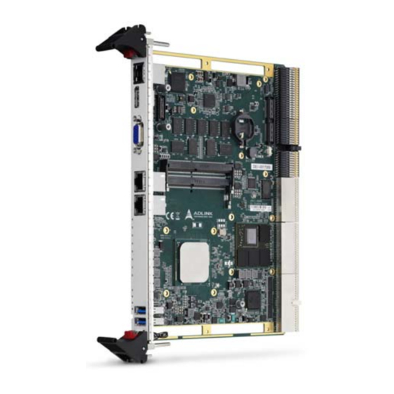
Page 33: Cpci-6940 Series Assembly Layout
4.2 cPCI-6940 Series Assembly Layout cPCI-6940 2.5” SATA Drive DDR4 SODIMM Heatsink CPU Heatsink Figure 4-3: cPCI-6940 Assembly Layout Board Interfaces... -
Page 34: Figure 4-4: Cpci-6940Dh Assembly Layout
Leading EDGE COMPUTING cPCI-6940DH 2.5” SATA Drive Figure 4-4: cPCI-6940DH Assembly Layout Board Interfaces... -
Page 35: Figure 4-5: Cpci-6940Dx Assembly Layout
cPCI-6940 cPCI-6940DX XMC connector Figure 4-5: cPCI-6940DX Assembly Layout Board Interfaces... -
Page 36: Cpci-6940 Series Faceplate
GbE A/B GbE A/B HDD LED HDD LED WDT LED WDT LED Figure 4-6: cPCI-6940 Series Faceplate Layout The cPCI-6940DH/DX uses the same faceplate design. For cPCI-6940DH with 2.5" SATA drive onboard, the XMC space cannot be used simultaneously NOTE: NOTE:... -
Page 37: Table 4-1: Cpci-6940 Faceplate System Led Descriptions
cPCI-6940 System LEDs Color Condition Indication System is off Power Green System Power ready (PWGD) Green Post OK No Watchdog event WDT* Blinking Watchdog event alert No SATA drive activity Yellow Blinking Data read/write in process for SATA drive Handles closed, system is on Fast Blink Preparing to shut down system (LED: 0.1s on, 0.9s off.) -
Page 38: Figure 4-7: Cpci-6940 Series Led Labels
“01110101”, then the port 80h output is “75h” (see “Checkpoints & Beep Codes” on page 107). Each LED indicates a corresponding bit of the port 80h POST code. Refer to the figure and table below. Figure 4-7: cPCI-6940 Series LED Labels LED 1 Port 80h bit0 LED 2... -
Page 39: Connector Pin Assignments
cPCI-6940 4.4 Connector Pin Assignments COM (RJ-45) Pin # RS-232 RS-422 RS-485 DCD# Data- RTS# — — DSR# — — — Data+ — — CTS# — — DTR#L — Table 4-2: Faceplate COM Pin Definitions COM RJ-45 to DB-9 Cable Pin # RS-232 RS-422... -
Page 40: Table 4-4: Displayport Connector Pin Definition
Leading EDGE COMPUTING DisplayPort Connector Pin # Signal Pin # Signal CN_DP0_P Ground CN_DP0_N CN_DP1_P Ground CN_DP1_N CN_DP2_P Ground CN_DP2_N CN_DP3_P Ground CN_DP3_N CN_CAD-L CN_CEC CN_AUX_P Ground CN_AUX_N DDP_HPD Ground P3V3 Table 4-4: DisplayPort Connector Pin Definition VGA Connector Signal Name Pin # Pin # Signal Name Green Blue N.C. -
Page 41: Table 4-6: Usb 3.0 Connector Pin Definition
cPCI-6940 USB 3.0 Connectors Pin # Signal Name USB3.0_P5VA USB2_CMAN USB2_CMAP USB3A_CMRXN USB3A_CMRXP USB3A_CMTXN USB3A_CMTXP Table 4-6: USB 3.0 Connector Pin Definition Board Interfaces... -
Page 42: Table 4-7: Rj-45 Gbe Pin Definitions
Leading EDGE COMPUTING RJ-45 Gigabit Ethernet Connectors Pin # GbE A/B TD0+ TD0- TD1+ TD2+ TD2- TD1- TD3+ TD3- Table 4-7: RJ-45 GbE Pin Definitions Speed Activity Speed LED Activity LED Status (Green/Orange) (Yellow) Network link is not established or system powered off Link 10 Mbps Active... - Page 43 cPCI-6940 SFP+ 10Gigabit Ethernet Connector (8HP versions only) Pin # 1000BASE-T SFP_TX_FAULT SFP_TX_DISABLE SFP_SDA SFP_SCL SFP_MOD_ABS SFP_RX_LOS SRDS_RX-N SRDS_RX-P SFP_V3P3_R SFP_V3P3_T SRDS_TX-P SRDS_TX-N Board Interfaces...
-
Page 44: Table 4-9: Serial Ata Connector With Power Pin Definition
Leading EDGE COMPUTING Serial ATA Connector with Power Pin # Signal Signal Power P13~P15 Table 4-9: Serial ATA Connector with power Pin Definition Board Interfaces... -
Page 45: Table 4-10: Cfast Socket Pin Definition
cPCI-6940 CFast Socket (on optional DB-CFAST adapter board) Pin # Signal Name Ground SATA_TX-P SATA_TX-N Ground SATA_RX-N SATA_RX-P Ground CFast_CDI Ground Ground CFast_LED1 CFast_LED2 +3.3V +3.3V Ground Ground CFast_CDO Table 4-10: CFast Socket Pin Definition Board Interfaces... -
Page 46: Table 4-11: Xmc Connector Pin Definition
Leading EDGE COMPUTING XMC Connector Pin# 3.3V VPWR Not used PCIE_RST-L 3.3V VPWR Not used Not used 3.3V VPWR Not used +12V 3.3V VPWR Not used -12V Not used VPWR Not used Not used VPWR Not used 3.3V VPWR Not used Not used VPWR Not used... -
Page 47: Table 4-12: Compactpci J1 Connector Pin Definition
cPCI-6940 CompactPCI J1 Connector CPCI_REQ64-L CPCI_ENUM-L P3V3 CPCI_ACK64- CPCI_AD1 V(I/O) CPCI_AD0 P3V3 CPCI_AD4 CPCI_AD3 CPCI_AD2 CPCI_AD7 P3V3 CPCI_AD6 CPCI_AD5 P3V3 CPCI_AD9 CPCI_AD8 CPCI_M66EN CPCI_CBE-L0 GND CPCI_AD12 CPCI_AD11 CPCI_AD10 P3V3 CPCI_AD15 CPCI_AD14 CPCI_AD13 CPCI_SERR-L P3V3 CPCI_PAR CPCI_CBE-L1 GND P3V3 IPMB_CLK IPMB_DAT CPCI_PERR-L GND GND CPCI_DEVSEL-L CPCI_STOP-L CPCI_LOCK-L GND... -
Page 48: Table 4-13: Compactpci J2 Connector Pin Definition
Leading EDGE COMPUTING CompactPCI J2 Connector CPCI_CLK6 CPCI_CLK5 IPMB_DAT IPMB_CLK P3V3_AUX J2_RSTBTN-L CPCI_REQ-L6 CPCI_GNT-L6 GND CPCI_DEGL CPCI_FAL-L CPCI_REQ-L5 CPCI_GNT-L5 GND CPCI_AD35 CPCI_AD34 CPCI_AD33 CPCI_AD32 CPCI_AD38 CPCI_AD37 CPCI_AD36 CPCI_AD42 CPCI_AD41 CPCI_AD40 CPCI_AD39 CPCI_AD45 CPCI_AD44 CPCI_AD43 CPCI_AD49 CPCI_AD48 CPCI_AD47 CPCI_AD46 CPCI_AD52 CPCI_AD51 CPCI_AD50 CPCI_AD56 CPCI_AD55... -
Page 49: Table 4-14: Compactpci J3 Connector Pin Definition
cPCI-6940 CompactPCI J3 Connector Pin Z 19 GND P12V 18 GND LAN4_TXDP0 LAN4_TXDN0 LAN4_TXDP2 LAN4_TXDN2 17 GND LAN4_TXDP1 LAN4_TXDN1 LAN4_TXDP3 LAN4_TXDN3 16 GND LAN3_TXDP0 LAN3_TXDN0 LAN3_TXDP2 LAN3_TXDN2 15 GND LAN3_TXDP1 LAN3_TXDN1 LAN3_TXDP3 LAN3_TXDN3 14 GND USB_OC3# USB_OC4# USB_OC5# USB_OCA# USB_OCB# 13 GND U2_DAP U2_DAN... -
Page 50: Table 4-15: Compactpci J4 Connector Pin Definition
Leading EDGE COMPUTING CompactPCI J4 Connector 25 GND PCIE_J4_TXP15 PLTRST_PCIEX16 PCIE_WAKE-L GND 24 GND PCIE_J4_TXN15 PCIE_J4_RXP13 23 GND PCIE_J4_TXP13 PCIE_J4_RXN13 PCIE_J4_RXP15 GND 22 GND PCIE_J4_TXN13 PCIE_J4_TXP14 PCIE_J4_RXP14 PCIE_J4_RXN15 GND 21 GND PCIE_J4_TXN14 PCIE_J4_TXP12 PCIE_J4_RXN14 20 GND PCIE_J4_TXP10 PCIE_J4_TXN12 PCIE_J4_RXP12 GND 19 GND PCIE_J4_TXN10 PCIE_J4_TXP11 PCIE_J4_RXP10 PCIE_J4_RXN12 GND 18 GND... -
Page 51: Table 4-16: Compactpci J5 Connector Pin Definition
cPCI-6940 CompactPCI J5 Connector 22 GND Power LED LAN3_LED_ACT-L LAN4_LED_ACT-L 21 GND USB3.0_TXAP USB3.0_TXAN USB3.0_RXAP USB3.0_RXAN 20 GND USB3.0_TXBP USB3.0_TXBN USB3.0_RXBP USB3.0_RXBN 19 GND SATA-RXP5 SATA-RXN5 SATA-TXP5 SATA-TXN5 18 GND DVI2_CLK_P DVI2_CLK_N 17 GND DVI2_DATA1_P DVI2_DATA1_N COM5_TX COM5_RX 16 GND DVI2_SDA DVI2_SCL DVI2_HPD... -
Page 52: Switches And Buttons
System Reset Button (SW14) The cPCI-6940 has a system reset button on the faceplate. See “cPCI-6940 Series Board Layout - Solder Side” on page 20 and “cPCI-6940 Series Faceplate” on page 24 for the button location. See “cPCI-6940 Series Board Layout” on page 19 for the follow- ing button and switch locations. - Page 53 cPCI-6940 VGA Output Settings (SW2) Sets the VGA output to the port on the faceplate or rear I/O. VGA to rear VGA to front (default) Serial Port Setting (SW6) Sets the mode of the COM port on the faceplate. Mode RS-232 (default) RS-422 RS-485...
- Page 54 Leading EDGE COMPUTING Debug Switches (SW11, SW12, SW_MOD1) Switches SW11, SW12 and SW_MOD1 are for debugging pur- poses and should be left in the default settings (all OFF). Mode Debug Switch (SW_MOD2) Switch SW_MOD2 is for debugging purposes and should be left in the default settings (all OFF).
- Page 55 cPCI-6940 COM Debug Switches (SW_COMDEG1, SW_COMPW1) Switch SW_COMDEG1 is set 1, 2 ON and 3, 4 OFF by default to set the faceplate RJ-45 COM (CN12) serial port as a stan- dard RS-232 serial port. The setting can be changed to use CN12 as an IPMI debugging port.
- Page 56 Leading EDGE COMPUTING This page intentionally left blank. Board Interfaces...
-
Page 57: Getting Started
This chapter describes the following installation procedures for the cPCI-6940. Memory module installation 2.5” SATA drive 5.1 CPU and Heatsink The cPCI-6940 Series come with CPU and heatsink pre-installed. Removal of heatsink/CPU by users is not recommended. Please contact your ADLINK service representative for assistance. Getting Started... -
Page 58: Memory Module Installation
Leading EDGE COMPUTING 5.2 Memory Module Installation The cPCI-6940 provides space to install two DRAM SODIMM mem- ory modules. Follow the instructions below to install memory mod- ules to the cPCI-6940. 1. Memory modules can be installed in the location marked below. - Page 59 cPCI-6940 3. Completed memory installation. If only one memory module is used, it must be installed in the upper memory slot (DIMM0). NOTE: NOTE: Getting Started...
-
Page 60: Sata Drive Installation
Leading EDGE COMPUTING 5.3 2.5" SATA Drive Installation The cPCI-6940 provides space to install a 2.5” SATA drive. 1. Locate the DB-LSATA SATA adapter board, screws for assembling the 2.5" SATA drive and the HDD bracket in the accessory pack. Insert the 2.5" SATA drive into the SATA adapter board. - Page 61 cPCI-6940 3. Turn the blade over and secure four screws as marked below. 4. Completed SATA drive installation. Getting Started...
- Page 62 Leading EDGE COMPUTING 5. Turn the blade over and secure with two screws as marked below to complete the SATA drive installation. Getting Started...
-
Page 63: Installing The Cpci-6940 To The Chassis
cPCI-6940 5.4 Installing the cPCI-6940 to the Chassis The cPCI-6940 may be installed in a system or peripheral slot of a 6U CompactPCI chassis. These instructions are for reference only. Refer to the user guide that comes with the chassis for more information. - Page 64 Leading EDGE COMPUTING This page intentionally left blank. Getting Started...
-
Page 65: Driver Installation
cPCI-6940 Driver Installation The cPCI-6940 drivers can be downloaded from the ADLINK web- site (http://www.adlinktech.com). ADLINK provides validated drivers for Windows 7 and Windows Server 2012. We recommend using these drivers to ensure compatibility. The VxWorks BSP can be downloaded from the cPCI-6940 product page on the ADLINK website 6.1 cPCI-6940 Drivers The following describes the cPCI-6940 driver installation proce-... - Page 66 Leading EDGE COMPUTING This page intentionally left blank. Driver Installation...
-
Page 67: Utilities
cPCI-6940 Utilities 7.1 Watchdog Timer This section describes the operation of the cPCI-6940’s watch dog timer (WDT). The primary function of the WDT is to monitor the cPCI-6940 operation and to reset the system if a software applica- tion fails to function as programmed. The following WDT functions may be controlled using a software application: enabling and disabling reloading timeout value... - Page 68 Leading EDGE COMPUTING WDT Sample Code #include <stdio.h> #include <stdlib.h> typedefunsigned charBYTE; void EnterConfig() outportb(SIO_CONFIG_INDEX, 0x87); outportb(SIO_CONFIG_INDEX, 0x01); outportb(SIO_CONFIG_INDEX, 0x55); outportb(SIO_CONFIG_INDEX, 0x55); void ExitConfig() outportb(SIO_CONFIG_INDEX, 0x02); outportb(SIO_CONFIG_DATA, 0x02); void LDNSelection(BYTE LDN) outportb(SIO_CONFIG_INDEX, 0x07); outportb(SIO_CONFIG_DATA, LDN); void SIOBasicIORead( BYTE LDN, BYTE Register, BYTE *Data) LDNSelection(LDN);...
- Page 69 cPCI-6940 LDNSelection(LDN); outportb(SIO_CONFIG_INDEX, Register); outportb(SIO_CONFIG_DATA, Data); BOOL StringToByte(char *string, BYTE *value) BYTE i, temp; *value = 0; for(i=0; string[i]!=NULL; ++i) { if(i>1) { printf("Digital count error!\n"); return 0; } *value <<= 4; temp = toupper(string[i]); if(temp >='0' && temp <='9') *value += temp - '0';...
- Page 70 Leading EDGE COMPUTING printf("Input char[%c] is illegal!\n", string[i]); return 0; if(temp > 65535) { printf("Input number is large than 65535!\n"); return1; int IT8786_WatchDog(int argc, char *argv[]) BYTE bTemp, bUnit; WORD wWdtimer; printf("ADLINK WatchDog DOS Utility [Version 1.00]\n\n"); if((argc != 3) && strcmp(argv[1], "/?")) { printf("Invalid command, please type /? to get the details.\n");...
- Page 71 cPCI-6940 printf("Argument1 is a invalid number[%d].\n", bUnit); return 1; StringToWORD_Dec(argv[2], &wWdtimer); EnterConfig(); // Implement Watch Dog SIOBasicIORead(0x07, 0x29, &bTemp); bTemp &= ~BIT6; // default function = KRST SIOBasicIOWrite(0x07, 0x29, bTemp); // Config settings if(bUnit) { bTemp = 0xd0; // second } else { bTemp = 0x50;...
-
Page 72: User Led Programming
Leading EDGE COMPUTING 7.2 User LED Programming The eight User LEDs on the front panel display port 80h POST codes in hexadecimal during boot up. Users can use the POST codes to identify issues during the BIOS POST process. In default mode, these eight LEDs display the POST code output to Port 80h during system bootup (see “User LEDs”... -
Page 73: Bios Setup Utility
cPCI-6940 BIOS Setup Utility The following chapter describes basic navigation for the AMI EFI BIOS setup utility. 8.1 Starting the BIOS To enter the setup screen, follow these steps: 1. Power on the motherboard 2. Press the < Delete > key on your keyboard when you see the following text prompt: <... - Page 74 Leading EDGE COMPUTING Setup Menu The main BIOS setup menu is the first screen that you can navi- gate. Each main BIOS setup menu option is described in this user’s guide. The Main BIOS setup menu screen has two main frames. The left frame displays all the options that can be configured.
- Page 75 cPCI-6940 Navigation Note: There is a hot key legend located in the right frame on most setup screens. Keyboard Commands < > The Left and Right "Arrow" keys allow you to select a setup screen. The Up and Down "Arrow" keys allow you to select a setup screen.
- Page 76 Leading EDGE COMPUTING Hotkey Descriptions Enter The < Enter > key allows you to display or change the setup option listed for a particular setup item. The < Enter > key can also allow you to display the setup sub-screens. The <...
- Page 77 cPCI-6940 The < F4 > key allows you to save any changes you have made and exit Setup. Press the < F10 > key to save your changes. The following screen will appear: Press the < Enter > key to save the configuration and exit. You can also use the <...
-
Page 78: Main Setup
Leading EDGE COMPUTING 8.2 Main Setup When you first enter the Setup Utility, you will enter the Main setup screen. You can always return to the Main setup screen by select- ing the Main tab. There are two Main Setup options. They are described in this section. - Page 79 cPCI-6940 Total Memory Displays the platform total memory size. SPS Firmware Version Displays the platform SPS firmware version. System Time/System Date Use this option to change the system time and date. Highlight Sys- tem Time or System Date using the < Arrow > keys. Enter new val- ues using the keyboard.
-
Page 80: Advanced Bios Setup
Leading EDGE COMPUTING 8.3 Advanced BIOS Setup Select the Advanced tab from the setup screen to enter the Advanced BIOS Setup screen. You can select any of the items in the left frame of the screen to go to the sub menu for that item. You can display an Advanced BIOS Setup option by highlighting it using the <... -
Page 81: Trusted Computing
cPCI-6940 8.3.1 Trusted Computing Trusted Computing is an industry standard to make personal com- puters more secure through a dedicated hardware chip, called a Trusted Platform Module (TPM). This option allows you to enable or disable the TPM support. Security Device Support OS will not show TPM. - Page 82 Leading EDGE COMPUTING Device Select TPM 1.2 will restrict support to TPM 1.2 devices, TPM 2.0 will restrict support to TPM 2.0 devices, Auto will support both with the default set to TPM 2.0 devices if not found, TPM 1.2 devices will be enumerated TPM Enabled Status Displays TPM enabled status.
-
Page 83: It8786 Super Io Configuration
cPCI-6940 8.3.2 IT8786 Super IO Configuration You can use this screen to select options for the IT8786 Super IO Configuration Settings. Use the up and down < Arrow > keys to select an item. Use the < + > and < - > keys to change the value of the selected option. -
Page 84: Console Redirection
Leading EDGE COMPUTING 8.3.3 Console Redirection You can use this screen to select options for the serial port con- sole redirection settings. Use the up and down < Arrow > keys to select an item. Use the < + > and < - > keys to change the value of the selected option. - Page 85 cPCI-6940 Terminal Type VT100+ is the preferred terminal type for out-of-band manage- ment. Configuration options: VT100, VT100+, VT-UTF8, ANSI. Bits per second Select the bits per second you want the serial port to use for console redirection. The options are 115200, 57600, 38400, 19200, 9600.
- Page 86 Leading EDGE COMPUTING VT-UTF8 Combo Key Support Enables VT-UTF8 combination key support for ANSI/VT100 terminals.Set this value to Enabled/Disabled. Recorder Mode When this mode is enabled, only text will be sent. This is to capture terminal data. Set this value to Enabled/Disabled. Resolution 100x31 Set this option to extended terminal resolution.
-
Page 87: Network Stack Configuration
cPCI-6940 8.3.4 Network Stack Configuration Network Stack Enable/Disable UEFI Network Stack. BIOS Setup Utility... -
Page 88: Csm Configuration
Leading EDGE COMPUTING 8.3.5 CSM Configuration CSM Support Enable/Disable CSM Support. GateA20 Active Upon Request: GA20 can be disabled using BIOS services. Always: do not allow disabling of GA20; this option is useful when any RT code is executed above 1MB. Option ROM Messages Set the display mode for Option ROM. - Page 89 cPCI-6940 Boot Option Filter This option controls Legacy/UEFI ROM priority. Set this value to UEFI and Legacy, Legacy only, UEFI only. Network Controls the execution of UEFI and Legacy PXE OpROM. Set this value to Do not launch, Legacy, UEFI. Storage Controls the execution of UEFI and Legacy PXE OpROM.
-
Page 90: Usb Configuration
Leading EDGE COMPUTING 8.3.6 USB Configuration You can use this screen to select options for the USB Configura- tion. Use the up and down < Arrow > keys to select an item. The screen is shown below. Legacy USB Support Enables legacy USB support. - Page 91 cPCI-6940 USB Mass Storage Driver Support Enable/Disable USB Mass Storage Driver Support. USB Transfer Time-out The time-out value for Control, Bulk and Interrupt transfers. Device Reset Time-out USB mass storage device Start Unit command time-out. Device Power-up Delay Maximum time the device will take before it properly reports itself to the Host Controller.
-
Page 92: Hardware Monitor
Leading EDGE COMPUTING 8.3.7 Hardware Monitor This option displays the current status of all of the monitored hard- ware devices/components such as voltages and temperatures. CPU Temperature Displays current CPU temperature. System Temperature Displays current system temperature. 3.3V Displays current system 3.3V voltage. Displays current system 5V voltage. -
Page 93: Chipset Setup
cPCI-6940 8.4 Chipset Setup Select the Chipset tab from the setup screen to enter the Chipset BIOS Setup screen. You can select any of Chipset BIOS Setup options by highlighting it using the < Arrow > keys. The Chipset BIOS Setup screen is shown below. BIOS Setup Utility... -
Page 94: Cpu Configuration
Leading EDGE COMPUTING 8.4.1 CPU Configuration You can use this screen to select options for the CPU Configura- tion Settings. Use the up and down < Arrow > keys to select an item. Use the < + > and < - > keys to change the value of the selected option. - Page 95 cPCI-6940 Enable Intel TXT Support Enables Intel Trusted Execution Technology Configuration. Enables the Vanderpool Technology, takes effect after reboot. Enable SMX Enables Safer Mode Extensions. Hardware Prefetcher MLC Streamer Prefetcher (MSR 1A4h Bit[0]) Adjacent Cache Prefetch MLC Spatial Prefetcher (MSR 1A4h Bit[1]) X2APIC Enable/Disable extended APIC support.
-
Page 96: Advanced Power Management Configuration
Leading EDGE COMPUTING 8.4.2 Advanced Power Management Configuration You can use this screen to select options for the Advanced Power Management Configuration Settings. Use the up and down < Arrow > keys to select an item. Use the < + > and < - > keys to change the value of the selected option. - Page 97 cPCI-6940 CPU P State Control P State Domain Per Logical: indicates the P-state domain for each logical proc in the system. Per Package: all procs indicate the same domain in the same package. P-state Coordination HW_ALL (hardware) coordination is recommended over SW_ALL and SW_ANY (software coordination).
- Page 98 Leading EDGE COMPUTING Boot Performance Mode Select the performance state that the BIOS will set before OS handoff. Turbo Mode Enable or Disable CPU Turbo mode. CPU C State Control C2C3TT Default = 0, means [AUTO]. C2 to C3 Transition Timer, PPDN_INIT = 1:10:1:74 Bit[11:0].
- Page 99 cPCI-6940 CPU C3 Report Enable/Disable CPU C3 (ACPI C2) report to OS. Recom- mended to be disabled. CPU C6 Report Enable/Disable CPU C6 (ACPI C2) report to OS Recom- mended to be enabled. Enhanced Halt State (C1E) Enables the Enhanced C1E state of the CPU. Takes effect after reboot.
-
Page 100: Memory Configuration
Leading EDGE COMPUTING 8.4.3 Memory Configuration You can use this screen to select options for the Memory Configu- ration Settings. Use the up and down < Arrow > keys to select an item. Use the < + > and < - > keys to change the value of the selected option. - Page 101 cPCI-6940 Memory Topology BIOS Setup Utility...
-
Page 102: Iio Configuration
Leading EDGE COMPUTING 8.4.4 IIO Configuration You can use this screen to select options for the Integrated I/O (IIO) Configuration Settings. Use the up and down < Arrow > keys to select an item. Use the < + > and < - > keys to change the value of the selected option. - Page 103 cPCI-6940 PCI-E ASPM Support This option enables/disables the ASPM support for all down- stream devices. Power Down Unused Ports Power down unused ports. Onboard VGA Control Enable/Disable onboard VGA. Active Video Select active Video type. IIO PCIe Port 3 Selects PCIe port bifurcation for PCIe x16 to J4 connector and XMC slot.
- Page 104 Leading EDGE COMPUTING Intel VT for Directed I/O (VT-d) Intel VT for Directed I/O (VT-d) Enable/Disable Intel Virtualization Technology for Directed I/O (VT-d) by reporting the I/O device assignment to VMM through DMAR ACPI Tables. ACS Control Enable: Programs ACS only to Chipset PCIe Root Ports Bridges;...
-
Page 105: Pch Configuration
cPCI-6940 8.4.5 PCH Configuration You can use this screen to select options for the PCH Configura- tion Settings. Use the up and down < Arrow > keys to select an item. Use the < + > and < - > keys to change the value of the selected option. - Page 106 Leading EDGE COMPUTING PCI Express Configuration PCI-E ASPM Support This option enables/disables the ASPM support for all down- stream devices. PCIE Clock Gating PCIE Clock Gating Enable/Disable for all PCH PCIE Ports. PCH DMI ASPM PCH DMI ASPM setting. DMI Link Extended Synch Control The control of Extended Synch on SB side of the DMI Link.
- Page 107 cPCI-6940 PCI Express Root Port 1 PCIE ASPM PCI Express Root port ASPM Setting. PCIe Speed Configure PCIe Speed. PCI Express Root Port 5 PCI Express Root Port 5 Control the PCI Express Root Port. PCIE ASPM PCI Express Root port ASPM Setting. PCIe Speed Configure PCIe Speed.
- Page 108 Leading EDGE COMPUTING PCH SATA Configuration SATA Controller Enable or Disable SATA controller. Configure SATA as This will configure SATA as IDE, RAID or AHCI. SATA Test Mode Enable/Disable SATA test mode. SATA AHCI LPM Enables/Disables Link Power Management. SATA Controller Speed Indicates the maximum speed the SATA controller can support.
- Page 109 cPCI-6940 Hot Plug Designates this port as Hot Pluggable. Configure as eSATA Configures port as external SATA (eSATA). Spin Up Device If enabled for any of ports Staggered Spin Up will be performed and only the drives which have this option enabled will spin up at boot.
- Page 110 Leading EDGE COMPUTING USB Configuration USB Precondition Precondition work on USB host controller and root ports for faster enumeration. xHCI Mode Mode of operation of xHCI controller. Trunk Clock Gating Enable/Disable BTCG. USB Ports Per-Port Disable Control Control each of the USB ports disabling. XHCI Idle L1 Enabled XHCI Idle L1.
-
Page 111: Security Setup
cPCI-6940 8.5 Security Setup Select the Security tab from the setup screen to enter the Security BIOS Setup screen. You can select any of Security BIOS Setup options by highlighting it using the < Arrow > keys. The Security BIOS Setup screen is shown below. Administrator Password Set Administrator Password. - Page 112 Leading EDGE COMPUTING Secure Boot Menu Secure Boot Secure Boot can be enabled if 1.System running in User mode with enrolled Platform Key(PK) 2.CSM function is disabled. Secure Boot Mode Secure Boot mode selector. 'Custom' Mode enables users to change Image Execution policy and manage Secure Boot Keys.
- Page 113 cPCI-6940 Key Management Provision Factory Default keys Install factory default Secure Boot keys when System is in Setup Mode. Enroll all Factory Default keys Force System to User Mode - install all Factory Default keys (PK, KEK, db, dbt, dbx). Change takes effect after reboot. Save all Secure boot variables Save NVRAM content of all Secure Boot variables to the files (EFI_SIGNATURE_LIST data format) in root folder on a target...
- Page 114 Leading EDGE COMPUTING 2. Authenticated UEFI Variable Key source: Default, Custom, Mixed(*) modified from Setup menu. Key Exchange Keys Enroll Factory Defaults or load the keys from a file with: 1. Public Key Certificate in: (a) EFI_SIGNATURE_LIST, (b) EFI_CERT_X509 (DER encoded), (c) EFI_CERT_RSA2048 (bin), (d) EFI_CERT_SHA256 (bin) 2.
-
Page 115: Boot Settings
cPCI-6940 8.6 Boot Settings Select the Boot tab from the setup screen to enter the Boot BIOS Setup screen. You can select any of the items in the left frame of the screen to go to the sub menu for that item. You can display a Boot BIOS Setup option by highlighting it using the <... -
Page 116: Save & Exit Menu
Leading EDGE COMPUTING 8.7 Save & Exit Menu Select the Save & Exit tab from the setup screen to enter the Save & Exit BIOS Setup screen. You can display any Save & Exit BIOS Setup option by highlighting it using the < Arrow > keys. The Save &... - Page 117 cPCI-6940 Save Changes Save changes done so far to any of the setup options. Discard Changes Discard changes done so far to any of the setup options. Restore Changes Restore/Load Defaults values for all the setup options. Save as User Defaults Save the changes done so far as user defaults..
- Page 118 Leading EDGE COMPUTING This page intentionally left blank. BIOS Setup Utility...
-
Page 119: Checkpoints & Beep Codes
cPCI-6940 Checkpoints & Beep Codes The eight User LEDs on the front panel display port 80h POST codes in hexadecimal during boot up. Users can use the POST codes to identify issues during the BIOS POST process (see See “User LEDs” on page 26.). Below are the BIOS checkpoints and beep codes for the cPCI- 6940. - Page 120 Leading EDGE COMPUTING Status Code Description 0x02 AP initialization before microcode loading North Bridge initialization before microcode 0x03 loading South Bridge initialization before microcode 0x04 loading 0x05 OEM initialization before microcode loading 0x06 Microcode loading 0x07 AP initialization after microcode loading North Bridge initialization after microcode 0x08 loading...
- Page 121 cPCI-6940 Status Code Description Pre-Memory North Bridge initialization (North 0x16 Bridge module specific) Pre-Memory North Bridge initialization (North 0x17 Bridge module specific) Pre-Memory North Bridge initialization (North 0x18 Bridge module specific) 0x19 Pre-memory South Bridge initialization is started Pre-memory South Bridge initialization (South 0x1A Bridge module specific) Pre-memory South Bridge initialization (South...
- Page 122 Leading EDGE COMPUTING Status Code Description Post-Memory North Bridge initialization (North 0x38 Bridge module specific) Post-Memory North Bridge initialization (North 0x39 Bridge module specific) Post-Memory North Bridge initialization (North 0x3A Bridge module specific) Post-Memory South Bridge initialization is 0x3B started Post-Memory South Bridge initialization (South 0x3C Bridge module specific)
- Page 123 cPCI-6940 Status Code Description S3 Resume Progress Codes S3 Resume is stared (S3 Resume PPI is called 0xE0 by the DXE IPL) 0xE1 S3 Boot Script execution 0xE2 Video repost 0xE3 OS S3 wake vector call 0xE4-0xE7 Reserved for future AMI progress codes S3 Resume Error Codes 0xE8 S3 Resume Failed...
- Page 124 Leading EDGE COMPUTING PEI Beep Codes # of Beeps Description Memory not Installed Memory was installed twice (InstallPeiMemory routine in PEI Core called twice) Recovery started DXEIPL was not found DXE Core Firmware Volume was not found Recovery failed S3 Resume failed Reset PPI is not available DXE Phase Status Code...
- Page 125 cPCI-6940 Status Code Description North Bridge DXE initialization (North Bridge 0x6F module specific) 0x70 South Bridge DXE initialization is started 0x71 South Bridge DXE SMM initialization is started 0x72 South Bridge devices initialization South Bridge DXE Initialization (South Bridge 0x73 module specific) South Bridge DXE Initialization (South Bridge 0x74...
- Page 126 Leading EDGE COMPUTING Status Code Description 0xA0 IDE initialization is started 0xA1 IDE Reset 0xA2 IDE Detect 0xA3 IDE Enable 0xA4 SCSI initialization is started 0xA5 SCSI Reset 0xA6 SCSI Detect 0xA7 SCSI Enable 0xA8 Setup Verifying Password 0xA9 Start of Setup Reserved for ASL (see ASL Status Codes 0xAA section below)
- Page 127 cPCI-6940 Status Code Description Some of the Architectural Protocols are not 0xD3 available 0xD4 PCI resource allocation error. Out of Resources 0xD5 No Space for Legacy Option ROM 0xD6 No Console Output Devices are found 0xD7 No Console Input Devices are found 0xD8 Invalid password Error loading Boot Option (LoadImage returned...
-
Page 128: Oem-Reserved Checkpoint Ranges
Leading EDGE COMPUTING ACPI/ASL Checkpoints Status Code Description 0x01 System is entering S1 sleep state 0x02 System is entering S2 sleep state 0x03 System is entering S3 sleep state 0x04 System is entering S4 sleep state 0x05 System is entering S5 sleep state 0x10 System is waking up from the S1 sleep state 0x20... -
Page 129: Ipmi User Guide
cPCI-6940 10 IPMI User Guide 10.1 Introduction This chapter is written for those who already have a basic under- standing of the newest implementation of the baseboard manage- ment controller (BMC) of the Intelligent Platform Management Interface (IPMI) specification rev. 2.0. It also describes the OEM extension IPMI command usages which are not listed in the IPMI specification. - Page 130 Leading EDGE COMPUTING Description IPMI Command NetFn CMD Spec (Required by PICMG 3.0/2.9) This command returns a GUID (Globally Unique ID), also referred to as a UUID Get Device GUID 20.8 (Universally Unique IDentifier), for the management controller. (Optional/Optional) This is a broadcast version of the ‘Get Broadcast "Get Device ID’...
- Page 131 cPCI-6940 Description IPMI Command NetFn CMD Spec (Required by PICMG 3.0/2.9) This global command is used to retrieve the present setting for the Event Receiver Slave Address and LUN. This command Get Event Receiver 29.2 is only applicable to management controllers that act as IPMB Event Generators.
- Page 132 Leading EDGE COMPUTING Description IPMI Command NetFn CMD Spec (Required by PICMG 3.0/2.9) This command provides the ability to disable or enable Event Message Set Sensor Event Generation for individual sensor events. 35.10 Enable The command is also used to enable or disable sensors in their entirety using the disable scanning bit.
-
Page 133: Compactpci Address Map
cPCI-6940 10.3 CompactPCI Address Map Since more than one system may be installed in a single chassis, we allocate each IPMB address based on GA input as peripheral cards. The CompactPCI Peripheral Address Mapping Table is given below. CompactPCI Peripheral Address Mapping Geo. -
Page 134: Ipmi Sensors List
Leading EDGE COMPUTING 10.5 IPMI Sensors List Sensor Reading Value of Sensor Normal Sensor name IPMI Get Sensor Reading Number Reading Command Timeout action: 000b = no action 001b = Hard Reset BMC Watchdog 000b = Power Down 011b = Power Cycle 100b - 111b = reserved +1.0V 1.0 V... -
Page 135: Relevant Documents
cPCI-6940 10.6 Relevant Documents Document Title Revision Source Intelligent Platform Document Revision 1.0 Intel Corp. Management Interface February 12, 2004 http://www.intel.com/design/ Specification v2.0 servers/ipmi/spec.htm PICMG 2.9 D1.0 January 21, 2000 CompactPCI System Management Specification Intelligent Platform Document Revision 0.15 Intel Corp. Management Bus June 24, 1997 http://www.intel.com/design/... - Page 136 Leading EDGE COMPUTING This page intentionally left blank. IPMI User Guide...
-
Page 137: Important Safety Instructions
cPCI-6940 Important Safety Instructions For user safety, please read and follow all instructions, WARNINGS, CAUTIONS, and NOTES marked in this manual and on the associated equipment before handling/operating the equipment. Read these safety instructions carefully. Keep this user’s manual for future reference. Read the specifications section of this manual for detailed information on the operating environment of this equipment. - Page 138 Leading EDGE COMPUTING Never attempt to fix the equipment. Equipment should only be serviced by qualified personnel. A Lithium-type battery may be provided for uninterrupted, backup or emergency power. Risk of explosion if battery is replaced with one of an incorrect type.
-
Page 139: Getting Service
San Jose, CA 95138, USA Tel: +1-408-360-0200 Toll Free: +1-800-966-5200 (USA only) Fax: +1-408-360-0222 Email: info@adlinktech.com ADLINK Technology (China) Co., Ltd. 300 Fang Chun Rd., Zhangjiang Hi-Tech Park Pudong New Area, Shanghai, 201203 China Tel: +86-21-5132-8988 Fax: +86-21-5132-3588 Email: market@adlinktech.com...
Need help?
Do you have a question about the cPCI-6940 Series and is the answer not in the manual?
Questions and answers