
Related Manuals for ADLINK Technology cPCIS-3330 Series


Summary of Contents for ADLINK Technology cPCIS-3330 Series
- Page 1 Series 8-Slot for 6U CompactPCI Platform User’s Manual Manual Rev. 2.00 Revision Date: May 30, 2005 Part No: 50-15017-100 Advance Technologies; Automate the World.
- Page 2 Copyright 2005 ADLINK TECHNOLOGY INC. All Rights Reserved. The information in this document is subject to change without prior notice in order to improve reliability, design, and function and does not represent a commitment on the part of the manufacturer.
- Page 3 Getting Service from ADLINK Customer Satisfaction is top priority for ADLINK Technology Inc. Please contact us should you require any service or assistance. ADLINK TECHNOLOGY INC. Web Site: http://www.adlinktech.com Sales & Service: Service@adlinktech.com TEL: +886-2-82265877 FAX: +886-2-82265717 Address: 9F, No. 166, Jian Yi Road, Chungho City,...
-
Page 5: Table Of Contents
Configurations ..........2 Specifications............... 3 Mechanical Layout............... 4 cPCIS-3330 Series Mechanical Layout ......4 cPCIS-3330 Series External Dimensions (mm) ....5 2 Getting Started ..............7 Shipping Contents ............... 7 CompactPCI Computing Blade & PSU Installation....7 CompactPCI Card Installation/Removal Procedure ..8 CompactPCI PSU Installation/Removal Procedure .. - Page 6 4 Cooling System..............59 Fan Alarm ................59 Fan Removal and Replacement ........59 Intake Fans ..............60 Front Exhaust Fans ............61 Rear Exhaust Fans ............62 Fan Tray Filter Replacement ..........62 5 Power Supply Unit ............63 Features................
-
Page 7: List Of Figures
List of Figures Figure 1-1: Mechanical Layout of the cPCIS-3330 ...... 4 Figure 1-2: cPCIS-3330 Series Front View........5 Figure 1-3: cPCIS-3330 Series Side View ........5 Figure 2-1: cPCIS-3330 Series slot layout........8 Figure 2-2: Installing 6U Processor Blade........9 Figure 2-3: Latching the cPCI module handles securely. -
Page 9: Introduction
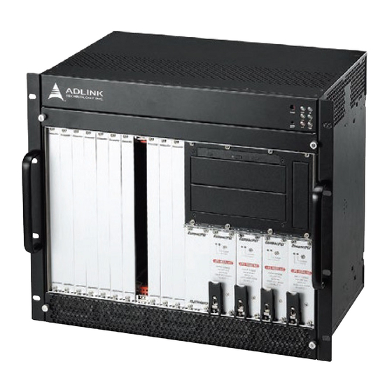
Introduction The cPCIS-3330 Series is a 19” 8-slot 6U CompactPCI Sub- system ideally suited to Network Equipment Providers, Computing Telephony Integrators and Voice over IP applications. This flexible and reliable development platform with optimized I/O and storage provides the best solution for equipment manufacturers and sys- tem integrators and shortens time-to-market for fast growing busi- ness revenues. -
Page 10: Cpcis-3330 Configurations
1.2 cPCIS-3330 Configurations The cPCIS-3330 Series comes in the configurations shown in the table below. . Model Number Description 8-slot 6U 32-bit CompactPCI Chassis with 4 cPCIS-3330/AC cPS-325/AC Redundant Power Supplies 8-slot 6U 64-bit CompactPCI Chassis with 4 cPCIS-3330/64/AC cPS-325/AC Redundant Power Supplies... -
Page 11: Specifications
1.3 Specifications CompactPCI Standards PICMG 2.0; 2.1; 2.5; 2.9; 2.11 Form Factor 6U cPCI with 80 mm depth rear I/O EIA RS-310C 19" 9U high rack-mount enclosure Enclosure Coated metal plate outer covering Guarded power switch and reset button 32-bit/33MHz PCI or 64-bit/33MHz PCI (model dependent) H.110 CT Bus Backplane... -
Page 12: Mechanical Layout
1.4 Mechanical Layout Refer to the figures below for the mechanical layout and external dimensions of the cPCIS-3330. cPCIS-3330 Series Mechanical Layout Figure 1-1: Mechanical Layout of the cPCIS-3330 Introduction... -
Page 13: Cpcis-3330 Series External Dimensions (Mm)
Series External Dimensions (mm) Figure 1-2: cPCIS-3330 Series Front View Figure 1-3: cPCIS-3330 Series Side View Introduction... - Page 14 Introduction...
-
Page 15: Getting Started
ADLINK. Check that the following items are included in the package. If there are any missing items, please contact your dealer: One cPCIS-3330 Series Subsystem This User’s Manual Accessory Kit (includes N. American or European power cord, air filter and spare screws) 2.2 CompactPCI Card &... -
Page 16: Compactpci Card Installation/Removal Procedure
Figure 2-1: cPCIS-3330 Series slot layout The handles on CompactPCI cards and PSUs ensure simple and safe installation and removal. Please follow the procedures below to install a CompactPCI module into a chassis: CompactPCI Card Installation/Removal Procedure 1. Place the sub-system on a level surface or rackmount it. - Page 17 they are pulled outwards) by first pressing on the release buttons with your thumb. 3. Carefully insert the module into the desired slot by slid- ing the edges of the board into the appropriate card guide rail. Take care to ensure correct alignment of the card with the chassis during insertion to prevent damage to the card and/or backplane.
-
Page 18: Compactpci Psu Installation/Removal Procedure
(if necessary), and reverse steps 1 through 5 above. CompactPCI PSU Installation/Removal Procedure The cPCIS-3330 Series come with cPS-H325 PSUs pre-installed. The removal and installation procedures for PSUs are the same as for CompactPCI cards, except there is only one handle. To replace a PSU module, refer to the figures and instructions below. -
Page 19: Rear Transition Module Installation/Removal
Figure 2-4: Unlatching and removing a cPCI PSU 2. Pull outwards to remove the PSU. 3. Insert the new PSU module, push on the handle until it latches into position, and replace the retaining screws. 2.3 Rear Transition Module Installation/Removal The installation and removal procedures for a Rear Transition Module (RTM) are the same as those for CompactPCI boards. -
Page 20: Drive Bay Access
2.4 Drive Bay Access To install the required hardware in the two 5.25”, one 3.5”, and one slim type CD-ROM drive bays, follow the procedure below: 1. Loosen the 8 screws securing the drive bay bracket to the cPCIS-3330 chassis as shown in the figure below. Figure 2-5: Remove drive bay bracket fastening screws 2. -
Page 21: Powering Up The System
Insert the desired boards into the appropriate card slots as described in Sections 2.2 and 2.3. The cPCIS-3330 Series features a guarded power switch. Use a suitably shaped object (such as a pen) to actuate the power switch. -
Page 22: System Alarm Board
Figure 2-7: cPCIS-3330 switch and LED legend 2.6 System Alarm Board The cPCIS-3330 Series features an embedded alarm board that monitors temperature and fan status. Should a fan become dis- abled or the temperature exceed 50 C, the Alarm LED will light up °... -
Page 23: Backplanes
In this chapter, we will describe the backplanes for the cPCIS-3330 Series. The following table outlines the backplanes that correspond to each model. Model Type Backplane Power cPCIS-3330/AC 32-bit/33MHz cBP-6108R cPCIS-3330/DC4 32-bit/33MHz cBP-6108R DC48V cPCIS-3330/64/AC 64-bit/33MHz cBP-6408R The cPCIS-3330 Series models use the cBP-3064 CompactPCI Power Backplane. Backplanes... -
Page 24: Cbp-6108R (32-Bit/33Mhz)
3.1 cBP-6108R (32-bit/33MHz) The backplane for the cPCIS-3330 Series 6U 32-bit, 8-slot chassis is the cBP-6108R, a 6U 8-slot H.110 32-bit CompactPCI back- plane with rear I/O. Features Standard CompactPCI 8-slot 32-bit backplane for 6U cPCI cards One segment with R-hand side system slot; 7 peripheral slots Supports 80mm P3 &... -
Page 25: Mechanical Drawing
Mechanical Drawing Figure 3-1: cBP-6108R Backplane Front View Backplanes... -
Page 26: Figure 3-2: Cbp-6108R Backplane Rear View
Figure 3-2: cBP-6108R Backplane Rear View Backplanes... -
Page 27: Connector Pin Assignments
Connector Pin Assignments System Slot: [1–P1] REQ64# ENUM# +3.3V AD[1] V(I/O) AD[0] ACK64# GND +3.3V AD[4] AD[3] AD[2] AD[7] +3.3V AD[6] AD[5] +3.3V AD[9] AD[8] M66EN C/BE[0]# GND AD[12] V(I/O) AD[11] AD[10] +3.3V AD[15] AD[14] AD[13] SERR# +3.3V C/BE[1]# GND +3.3V IPMB_SCL IPMB_SDA... - Page 28 System Slot: [1–P2] CLK6 Reserved Reserved Reserved CLK5 Reserved Reserved SMDATA SMCLK ALERT# Reserved Reserved Reserved Reserved Reserved PRST# REQ6# GNT6# Reserved Reserved DEG# Reserved Reserved FAL# REQ5# GNT5# Reserved Reserved Reserved Reserved Reserved V(I/O) Reserved Reserved Reserved Reserved Reserved Reserved Reserved V(I/O)
- Page 29 System Slot: [1–P3] PPWRGD PDCS16# PIORDY AP3D19 PIRQ PDACT# AP3B18 PCS3# PCS1# PPDIAG PDD15 PDD14 PDD13 PDD12 AP3E17 PDD11 PDD10 PDD9 PDD8 DDAK0# PDA0 PDA1 PDA2 DDRQ0 PDD7 PDD6 PDD5 PDD4 DIOW0# PDD3 PDD2 PDD1 PDD0 DIOR0# DR0# MSEN0 MTR0# INDEX# WDATA# DR1#...
- Page 30 System Slot: [1–P4] Reserved Reserved Reserved Reserved Reserved Reserved Reserved Reserved Reserved Reserved Reserved Reserved Reserved Reserved Reserved Reserved Reserved Reserved Reserved Reserved Reserved Reserved Reserved Reserved Reserved Reserved Reserved Reserved Reserved Reserved Reserved Reserved Reserved Reserved Reserved Reserved Reserved Reserved Reserved Reserved...
- Page 31 System Slot: [1–P5] Reserved Reserved Reserved Reserved Reserved Reserved Reserved Reserved Reserved Reserved Reserved Reserved Reserved Reserved Reserved Reserved Reserved Reserved Reserved Reserved Reserved Reserved Reserved Reserved Reserved Reserved Reserved Reserved Reserved Reserved Reserved Reserved Reserved Reserved Reserved Reserved Reserved Reserved Reserved Reserved...
- Page 32 Peripheral Slot: [2–P1] - [8–P1] REQ64# ENUM# +3.3V AD[1] V(I/O) AD[0] ACK64# GND +3.3V AD[4] AD[3] AD[2] AD[7] +3.3V AD[6] AD[5] +3.3V AD[9] AD[8] M66EN C/BE[0]# GND AD[12] V(I/O) AD[11] AD[10] +3.3V AD[15] AD[14] AD[13] SERR# +3.3V C/BE[1]# GND +3.3V IPMB_SCL IPMB_SDA PERR#...
- Page 33 Peripheral Slot: [2–P3] - [8–P3] Reserved Reserved Reserved Reserved Reserved Reserved Reserved Reserved Reserved Reserved Reserved Reserved Reserved Reserved Reserved Reserved Reserved Reserved Reserved Reserved Reserved Reserved Reserved Reserved Reserved Reserved Reserved Reserved Reserved Reserved Reserved Reserved Reserved Reserved Reserved Reserved Reserved Reserved...
- Page 34 Peripheral Slot: [2–P4] - [8–P4] SGA4 SGA3 SGA2 SGA1 SGA0 +12V Reserved CT_EN# -12V CT_MC PFS0# CT_RESET Reserved Reserved Reserved GND -SELVbat PFS1# Reserved Reserved -SELVbat Rtn No Pin No Pin No Pin No Pin No Pin No Pin No Pin No Pin No Pin No Pin...
- Page 35 Peripheral Slot: [2–P5] - [8–P5] Reserved Reserved Reserved Reserved Reserved Reserved Reserved Reserved Reserved Reserved Reserved Reserved Reserved Reserved Reserved Reserved Reserved Reserved Reserved Reserved Reserved Reserved Reserved Reserved Reserved Reserved Reserved Reserved Reserved Reserved Reserved Reserved Reserved Reserved Reserved Reserved Reserved Reserved...
- Page 36 IDE Add-on Card: [0–P3] +12V +12V +12V GND PPWRGD PDCS16# PIORDY AP3D19 PIRQ GND PDACT# AP3B18 PCS3# PCS1# PPDIAG GND PDD15 PDD14 PDD13 PDD12 AP3E17 GND PDD11 PDD10 PDD9 PDD8 DDAK0# GND PDA0 PDA1 PDA2 DDRQ0 PDD7 PDD6 PDD5 PDD4 DIOW0# GND PDD3 PDD2...
- Page 37 SM Bus Connector [CN1] Signal DATA V(I/O) ALERT# ATX Power Connector [J2, J3, J4] Signal Signal +3.3V +3.3V +3.3V -12V INH# FAL# 5V STB +12V H.110 DC Power Terminal [J1 - J4] Connector Signal -SELVbat -SELVbat Rtn VRGRtn Backplanes...
- Page 38 RST# Connector [J8] Signal PRSTA# FAL# Connector [J15] Signal FAL# INH# Connector [J16] Signal INH# Power LED Connector [J18] Signal Signal +12V -12V +3.3V Power Sense Connector [JP2] Signal +12V +3.3V Backplanes...
- Page 39 Secondary IDE Connector [J10] Signal Signal Reset IDE Ground Host data 7 Host data 8 Host data 6 Host data 9 Host data 5 Host data 10 Host data 4 Host data 11 Host data 3 Host data 12 Host data 2 Host data 13 Host data 1 Host data 14...
- Page 40 Primary IDE Connector [J19] Signal Signal Reset IDE Ground Host data 7 Host data 8 Host data 6 Host data 9 Host data 5 Host data 10 Host data 4 Host data 11 Host data 3 Host data 12 Host data 2 Host data 13 Host data 1 Host data 14...
- Page 41 Floppy Connector [J20] Signal Signal Ground DENSL# Ground No connect No connect MSEN0 Ground IDEX# Ground MIR0# Ground DR1# Ground DR0# Ground MTR1# Ground DIR# Ground STER# Ground WDATA# Ground WGATE# Ground TRK0# Ground Ground RDATA# Ground HDSEL# Ground DSKCHG# Backplanes...
-
Page 42: Jumper Settings
Jumper Settings H.110 CT Bus Shelf Address Header [JP1] Column 1 Column 2 Column 3 SGA0 SGA1 SGA2 SGA3 SGA4 (default: 1-2 shorted) V(I/O) Select [J5 - J6 - J7] Connector Signal V(I/O) +3.3V (default: J5-J6 shorted) Backplanes... -
Page 43: Cbp-6408R (64-Bit/66Mhz)
3.2 cBP-6408R (64-bit/33MHz) The backplane for the cPCIS-3330 Series 6U 64-bit, 8-slot chassis is the cBP-6408R, a 6U 64-bit, 8-slot, H.110 CompactPCI back- plane with rear I/O. Features Standard CompactPCI 8-slot 64-bit backplane for 6U cPCI cards One segment with R-hand side system slot; 7 peripheral slots Supports 80mm P3 &... -
Page 44: Mechanical Drawing
Mechanical Drawing Figure 3-3: cBP-6408R Backplane Front View Backplanes... -
Page 45: Figure 3-4: Cbp-6408R Backplane Rear View
Figure 3-4: cBP-6408R Backplane Rear View Backplanes... -
Page 46: Connector Pin Assignments
Connector Pin Assignments System Slot: [1–P1] REQ64# ENUM# +3.3V AD[1] V(I/O) AD[0] ACK64# GND +3.3V AD[4] AD[3] AD[2] AD[7] +3.3V AD[6] AD[5] +3.3V AD[9] AD[8] M66EN C/BE[0]# GND AD[12] V(I/O) AD[11] AD[10] +3.3V AD[15] AD[14] AD[13] SERR# +3.3V C/BE[1]# GND +3.3V IPMB_SCL IPMB_SDA... - Page 47 System Slot: [1–P2] CLK6 Reserved Reserved Reserved CLK5 Reserved Reserved SMDATA SMCLK ALERT# Reserved Reserved Reserved Reserved Reserved PRST# REQ6# GNT6# Reserved Reserved DEG# Reserved Reserved FAL# REQ5# GNT5# AD[35] AD[34] AD[33] AD[32] AD[38] V(I/O) AD[37] AD[36] AD[42] AD[41] AD[40] AD[39] AD[45] V(I/O)
- Page 48 System Slot: [1–P3] Reserved Reserved Reserved Reserved Reserved Reserved Reserved Reserved Reserved Reserved Reserved Reserved Reserved Reserved Reserved Reserved Reserved Reserved Reserved Reserved Reserved Reserved Reserved Reserved Reserved Reserved Reserved Reserved Reserved Reserved Reserved Reserved Reserved Reserved Reserved Reserved Reserved Reserved Reserved Reserved...
- Page 49 System Slot: [1–P4] Reserved Reserved Reserved Reserved Reserved Reserved Reserved Reserved Reserved Reserved Reserved Reserved Reserved Reserved Reserved Reserved Reserved Reserved Reserved Reserved Reserved Reserved Reserved Reserved Reserved Reserved Reserved Reserved Reserved Reserved Reserved Reserved Reserved Reserved Reserved Reserved Reserved Reserved Reserved Reserved...
- Page 50 System Slot: [1–P5] Reserved Reserved Reserved Reserved Reserved Reserved Reserved Reserved Reserved Reserved Reserved Reserved Reserved Reserved Reserved Reserved Reserved Reserved Reserved Reserved Reserved Reserved Reserved Reserved Reserved Reserved Reserved Reserved Reserved Reserved Reserved Reserved Reserved Reserved Reserved Reserved Reserved Reserved Reserved Reserved...
- Page 51 Peripheral Slot: [2–P1] - [8–P1] REQ64# ENUM# +3.3V AD[1] V(I/O) AD[0] ACK64# GND +3.3V AD[4] AD[3] AD[2] AD[7] +3.3V AD[6] AD[5] +3.3V AD[9] AD[8] M66EN C/BE[0]# GND AD[12] V(I/O) AD[11] AD[10] +3.3V AD[15] AD[14] AD[13] SERR# +3.3V C/BE[1]# GND +3.3V IPMB_SCL IPMB_SDA PERR#...
- Page 52 Peripheral Slot: [2–P2] - [8–P2] Reserved Reserved Reserved Reserved Reserved Reserved Reserved Reserved Reserved Reserved Reserved Reserved Reserved Reserved Reserved Reserved Reserved Reserved Reserved Reserved Reserved Reserved Reserved Reserved Reserved Reserved AD[35] AD[34] AD[33] AD[32] AD[38] V(I/O) AD[37] AD[36] AD[42] AD[41] AD[40] AD[39]...
- Page 53 Peripheral Slot: [2–P3] - [8–P3] Reserved Reserved Reserved Reserved Reserved Reserved Reserved Reserved Reserved Reserved Reserved Reserved Reserved Reserved Reserved Reserved Reserved Reserved Reserved Reserved Reserved Reserved Reserved Reserved Reserved Reserved Reserved Reserved Reserved Reserved Reserved Reserved Reserved Reserved Reserved Reserved Reserved Reserved...
- Page 54 Peripheral Slot: [2–P4] - [8–P4] SGA4 SGA3 SGA2 SGA1 SGA0 +12V Reserved CT_EN# -12V CT_MC PFS0# CT_RESET Reserved Reserved Reserved GND -SELVbat PFS1# Reserved Reserved -SELVbat Rtn No Pin No Pin No Pin No Pin No Pin No Pin No Pin No Pin No Pin No Pin...
- Page 55 Peripheral Slot: [2–P5] - [8–P5] Reserved Reserved Reserved Reserved Reserved Reserved Reserved Reserved Reserved Reserved Reserved Reserved Reserved Reserved Reserved Reserved Reserved Reserved Reserved Reserved Reserved Reserved Reserved Reserved Reserved Reserved Reserved Reserved Reserved Reserved Reserved Reserved Reserved Reserved Reserved Reserved Reserved Reserved...
- Page 56 SM Bus Connector [CN1] Signal DATA V(I/O) ALERT# Power Sense Connector [CN2] Signal +12V +3.3V ATX Power Connector [J2, J4, J5] Signal Signal +3.3V +3.3V +3.3V -12V INH# FAL# 5V STB +12V Backplanes...
- Page 57 H.110 DC Power Terminal [J6 - J11] Connector Signal -SELVbat -SELVbat Rtn VRG Rtn -Vbat (-48V) -Vbat Rtn Power LED Connector [J12] Signal Signal +12V -12V +3.3V RST# Connector [J13] Signal PRSTA# FAL# Connector [J14] Signal FAL# INH# Connector [J15] Signal INH# Backplanes...
-
Page 58: Jumper Settings
Jumper Settings H.110 CT Bus Shelf Address Header [JP1] Column 1 Column 2 Column 3 SGA0 SGA1 SGA2 SGA3 SGA4 (default: 1-2 shorted) V(I/O) Select [J16 - J17 - J18] Connector Signal V(I/O) +3.3V (default: J16-J17 shorted) Backplanes... -
Page 59: Cbp-3064 Compactpci Power Backplane
3.3 cBP-3064 CompactPCI Power Backplane The power backplane for the cPCIS-3330 8-slot chassis is the cBP-3064. Specifications PICMG 2.11 3U CompactPCI 47-pin Power Backplane Dimension: 161.56 x 128.7 (mm, W x H) Power Module Sockets: four DC output (ATX connector): four Cascading Current Sharing Cascading Voltage Sense: Dedicated voltage sense connector... -
Page 60: Mechanical Drawing
Mechanical Drawing Figure 3-5: cBP-3064 Power Backplane Front View Figure 3-6: cBP-3064 Power Backplane Rear View Backplanes... -
Page 61: Connector Pin Assignments
Connector Pin Assignments CompactPCI 47-Pin PSU Connector: Power 1-4 [CN1-CN4] Signal Signal ACL/-DC IN ACN/+DC IN V1 SENSE CGND V1ADJ V3 SHARE IPMB_PWR +FAL# RESERVED V2 SHARE IPMB_SDA INH# RESERVED DEG# IPMB_SCL V3 SENSE V1 SHARE S RTN 13-18 V2 SENSE 5-12 V2ADJ AC-Inlet Connector [CN5]... - Page 62 IPMB Connector [CN7] Signal DATA V(I/O) ALERT# Power Sense Connector [CN6, CN8] Signal Ground +3.3V -12V +12V Current Share Connector [CN9, CN10] Signal Ground +3.3V -12V +12V Backplanes...
- Page 63 DC Power Out [CN11, C12, CN13, CN14]) Signal Signal +3.3V +3.3V +3.3V -12V INH# FAL# DEG# +12V INH#1 Connector [J1] Signal INH#1 INH#2 Connector [J2] Signal INH#2 INH#3 Connector [J3] Signal INH#3 INH#4 Connector [J4] Signal INH#4 Backplanes...
- Page 64 DEG#/FAL# (1, 2) Connector [J5] Signal DEG#1 FAL#1 RSV23A RSV26A DEG#2 FAL#2 RSV23B RSV26B DEG#/FAL# (3, 4) Connector [J5] Signal DEG#3 FAL#3 RSV23C RSV26C DEG#4 FAL#4 RSV23D RSV26D INH# Connector [J7] Signal INH# Backplanes...
-
Page 65: Cooling System
Cooling System The cPCIS-3330 Series subsystems are equipped with 10 front- access hot swappable fans (five intake on the bottom, five exhaust on the top) and two rear-access hot swappable fans to provide an effectively cooled environment. The chassis is equipped with an air filter that is removable for cleaning and/or replacement. -
Page 66: Intake Fans
Intake Fans 1. Loosen the two screws attaching the intake fan tray cover at the base of the chassis and remove the cover. Figure 4-2: Remove the intake fan tray cover (note filter location) 2. Remove the two screws securing the faulty fan module, lift the handle, and pull the module out of the fan tray. -
Page 67: Front Exhaust Fans
Figure 4-4: Remove the faulty intake fan module 3. Replace with a functional fan module and reinstall the fan tray cover. Front Exhaust Fans 1. Loosen the two screws attaching the exhaust fan tray cover and remove the cover. 2. Remove the two screws securing the fan module, lift the handle, and pull the faulty fan module out of the fan tray. -
Page 68: Rear Exhaust Fans
3. Replace with a functional fan module and reinstall the fan tray cover. Rear Exhaust Fans 1. Loosen the four screws securing the rear exhaust fan module and pull the faulty fan module out of the chassis. Figure 4-6: Loosen the screws securing the rear fan module 2. -
Page 69: Power Supply Unit
Power Supply Unit The cPCIS-3330 Series Subsystems are equipped with four ADLINK cPS-H325 CompactPCI power modules (AC or DC input). 5.1 Features PICMG 2.11 CompactPCI power interface compliant 250W 3U X 8HP Eurocard package Meets IEC1000-3-2 harmonic correction Internal OR-ing diodes for N+1 redundancy... -
Page 70: Input Characteristics
5.3 Input Characteristics Input Voltage: 100-240 ± 10% VAC (cPS-H325/AC) 36 - 72 VDC (cPS-H325/48) Power Factor Correction: Meets Harmonic Correction IEC1000-3-2. Power Factor typ. 0.95-0.97 Input Connector: Positronic 47-pin PCIH47M400A1 Input Frequency: 47-63Hz Inrush Current: < 30A @ 230VAC (cPS-H325/AC only) Input Current: 2.8A @115VAC / 1.4A @230VAC (cPS-H325/AC) 7A @ 48VDC (cPS-H325/48) Dielectric Withstand: Meets IEC950 regulations... -
Page 71: Output Characteristics
5.4 Output Characteristics Output Current (A) Output Voltage (see below for properties) MIN. MAX. TYP. PEAK. MAIN +VO1 33.0 25.0 – (1, 2, 3, 4, 6) 3.3V AUX. +VO2 33.0 18.0 – (1, 2, 3, 4, 6, 7) AUX. +VO3 (1, 2, 3, 4, 6, 7) -12V AUX. - Page 72 Noise & Ripple: Typ. 1% peak to peak or 50mV, whichever is greater. OVP: Built-in at all outputs. Adjustability: Available at VO1, 2 & 3. Output Trim: Electrical trim available at VO1/VO2 [ADJ #]. Remote Sensing: Available at VO1, VO2 & VO3. Hot-Swap: Available.
-
Page 73: Important Safety Instructions
Important Safety Instructions Please read and follow all instructions marked on the product and in the documentation before operating the system. Retain all safety and operating instructions for future use. Please read these safety instructions carefully. Please keep this User’s Manual for future reference. The equipment should be operated in an ambient tempera- °... - Page 74 Openings in the case are provided for ventilation. Do not block or cover these openings. Make sure there is adequate space around the system for ventilation when setting up the work area. Never insert objects of any kind into the ventila- tion openings.
-
Page 75: Warranty Policy
Warranty Policy Thank you for choosing ADLINK. To understand your rights and enjoy all the after-sales services we offer, please read the follow- ing carefully. 1. Before using ADLINK’s products please read the user man- ual and follow the instructions exactly. When sending in damaged products for repair, please attach an RMA appli- cation form which can be downloaded from: http:// rma.adlinktech.com/policy/. - Page 76 3. Our repair service is not covered by ADLINK's two-year guarantee in the following situations: Damage caused by not following instructions in the user's manual. Damage caused by carelessness on the user's part dur- ing product transportation. Damage caused by fire, earthquakes, floods, lightening, pollution, other acts of God, and/or incorrect usage of voltage transformers.
Need help?
Do you have a question about the cPCIS-3330 Series and is the answer not in the manual?
Questions and answers