
Related Manuals for ADLINK Technology cBP-3210PR


Summary of Contents for ADLINK Technology cBP-3210PR
- Page 1 3U 10-slot cPCI PlusIO Hybrid Backplane Quick Reference Guide Manual Revision: 1.00 Revision Date: September 29, 2014 Part Number: 50-1Z163-1000 Advance Technologies; Automate the World.
- Page 2 ©Copyright 2014 ADLINK Technology Inc. All Rights Reserved. The information in this document is subject to change without prior notice in order to improve reliability, design and function and does not represent a commitment on the part of the manufacturer.
-
Page 3: Specifications
Backplane The cBP-3210PR is a 3U CompactPCI PlusIO hybrid 32-bit backplane with rear I/O. Specifications • Standard CompactPCI height for 3U cPCI cards • CompactPCI Compliancy PICMG 2.0 CompactPCI core specification R3.0 PICMG 2.30 CompactPCI PlusIO PICMG S.0 CompactPCI Serial •... - Page 4 Architecture PICMG PICMG PICMG PICMG PICMG PICMG PICMG PICMG PICMG PICMG PICMG cPCI- cPCI- cPCI- cPCI- 2.30 Periph. Periph. Periph. Periph. Periph. System R(I/O) R(I/O) R(I/O) R(I/O) R(I/O) Periph. Periph. Periph. Periph. Slot cPCI Serial Connector PICMG Legacy cPCI P2 (Rear I/O) Connector 2.30 P2 cPCI Serial Slots Legacy cPCI P1 Connector...
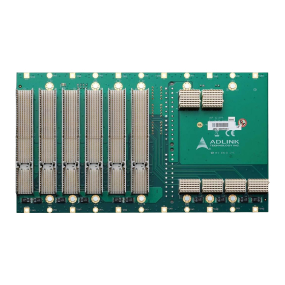
- Page 5 Mechanical Drawings 224.06 cBP-3210PR Front View CN1 CN2 rP10 rP12 cBP-3210PR Rear View...
- Page 6 Pin Assignments 3U cPCI System Slot 1 (P1 & P2) Conn -12V TRST +12V INTA# INTB# INTC# INTD# IPMB_PWR HEALTHY# INTP INTS BRSVP1A5 BRSVP1B5 RST# GNT0# REQ0# +3.3V CLK0 AD[31] AD[30] AD[29] AD[28] AD[27] AD[26] AD[25] AD[24] C/BE[3]# AD[23] AD[22] AD[21] +3.3V AD[20]...
- Page 7 3U cPCI Peripheral Slot 1 (P3 & P4) Conn -12V TRST +12V INTD# INTA# INTB# INTC# IPMB_PWR HEALTHY# INTP INTS BRSVP1A5 BRSVP1B5 RST# GNT0# REQ0# +3.3V CLK0 AD[31] AD[30] AD[29] AD[28] AD[27] AD[26] AD[25] AD[24] C/BE[3]# IDSEL AD[23] AD[22] AD[21] +3.3V AD[20] AD[19]...
- Page 8 3U cPCI Peripheral Slot 2 (P5 & P6) Conn -12V TRST +12V INTC# INTD# INTA# INTB# IPMB_PWR HEALTHY# INTP INTS BRSVP1A5 BRSVP1B5 RST# GNT1# REQ1# +3.3V CLK1 AD[31] AD[30] AD[29] AD[28] AD[27] AD[26] AD[25] AD[24] C/BE[3]# IDSEL AD[23] AD[22] AD[21] +3.3V AD[20] AD[19]...
- Page 9 3U cPCI Peripheral Slot 3 (P7 & P8) Conn -12V TRST +12V INTB# INTC# INTD# INTA# IPMB_PWR HEALTHY# INTP INTS BRSVP1A5 BRSVP1B5 RST# GNT2# REQ2# +3.3V CLK2 AD[31] AD[30] AD[29] AD[28] AD[27] AD[26] AD[25] AD[24] C/BE[3]# IDSEL AD[23] AD[22] AD[21] +3.3V AD[20] AD[19]...
- Page 10 3U cPCI Peripheral Slot 4 (P9 & P10) Conn -12V TRST +12V INTA# INTB# INTC# INTD# IPMB_PWR HEALTHY# INTP INTS BRSVP1A5 BRSVP1B5 RST# GNT3# REQ3# +3.3V CLK3 AD[31] AD[30] AD[29] AD[28] AD[27] AD[26] AD[25] AD[24] C/BE[3]# IDSEL AD[23] AD[22] AD[21] +3.3V AD[20] AD[19]...
- Page 11 3U cPCI Peripheral Slot 5 (P11 & P12) Conn -12V TRST +12V INTD# INTA# INTB# INTC# IPMB_PWR HEALTHY# INTP INTS BRSVP1A5 BRSVP1B5 RST# GNT4# REQ4# +3.3V CLK4 AD[31] AD[30] AD[29] AD[28] AD[27] AD[26] AD[25] AD[24] C/BE[3]# IDSEL AD[23] AD[22] AD[21] +3.3V AD[20] AD[19]...
- Page 12 Peripheral Serial Slot 1 (P13 & P14) Conn +12V STANDBY +12V +12V I²C_SCL I²C_SDA reserved reserved 1_USB2+ 1_USB2- PE_CLKIN+ PE_CLKIN- 1_PE_Tx00+ 1_PE_Tx00- 1_PE_Rx00+ 1_PE_Rx00- 1_ETH_A+ 1_ETH_A- 1_ETH_B+ 1_ETH_B- 2_ETH_A+ 2_ETH_A- 2_ETH_B+ 2_ETH_B- Conn +12V +12V +12V +12V RST# PCIE_EN# SATA_SDI SATA_SDO SATA_SCL SATA_SL...
- Page 13 Peripheral Serial Slot 2 (P15 & P16) Conn +12V STANDBY +12V +12V I²C_SCL I²C_SDA reserved reserved 1_USB2+ 1_USB2- PE_CLKIN+ PE_CLKIN- 1_PE_Tx00+ 1_PE_Tx00- 1_PE_Rx00+ 1_PE_Rx00- 1_ETH_A+ 1_ETH_A- 1_ETH_B+ 1_ETH_B- 8_ETH_A+ 8_ETH_A- 8_ETH_B+ 8_ETH_B- Conn +12V +12V +12V +12V RST# PCIE_EN# SATA_SDI SATA_SDO SATA_SCL SATA_SL...
- Page 14 Peripheral Serial Slot 3 (P17) Conn +12V STANDBY +12V +12V I²C_SCL I²C_SDA reserved reserved 1_USB2+ 1_USB2- PE_CLKIN+ PE_CLKIN- 1_PE_Tx00+ 1_PE_Tx00- 1_PE_Rx00+ 1_PE_Rx00- Conn +12V +12V +12V +12V RST# PCIE_EN# SATA_SDI SATA_SDO SATA_SCL SATA_SL 3_SATA_Tx+ 3_SATA_Tx- 3_SATA_Rx+ 3_SATA_Rx- Peripheral Serial Slot 4 (P18) Conn +12V STANDBY...
- Page 15 PRST# Connector (CN1) - Reset System Slot blade Signal PRST# INH# Connector (CN2) - “ON/OFF” switch Signal INH# IPMB Connector (CN3) - Intelligent Platform Management Bus Signal IPMB_SDA IPMB_SCL IPMB_PWR V(I/O) Power +5V Selectable Connector (CN4) V(I/O) Power +3.3V Selectable Connector (CN5) V(I/O) Power Selectable Connector (CN6)
- Page 16 ATX 20-pin Connector (CN7) Signal Signal +3.3V +3.3V +3.3V -12V INH# +5V_SB +12V ATX 24-pin Connector (CN8) Signal Signal +3.3V +3.3V +3.3V -12V INH# +5V_SB +12V +12V +3.3V PWR LED (JP1) - Power LED header for +12V, -12V, +5V and +3.3V Signal Signal +12V...
-
Page 17: Important Safety Instructions
Important Safety Instructions Read and follow all instructions marked on the product and in the documentation before you operate your system. Retain all safety and operating instructions for future use. Please read these safety instructions carefully. Please keep this User‘s Manual for later reference. The equipment should be operated only from the type of power source indicated on the rating label.
Need help?
Do you have a question about the cBP-3210PR and is the answer not in the manual?
Questions and answers