
Related Manuals for Delta INX Series


Summary of Contents for Delta INX Series
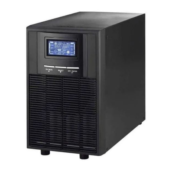
- Page 1 The power behind competitiveness Delta UPS - Amplon Family INX Series, Single Phase 1/ 2/ 3 kVA User Manual www.deltaelectronicsindia.com...
- Page 2 Failure to heed these instructions and warnings will void the warranty. Copyright © 2022 by Delta Electronics Inc. All Rights Reserved. All rights of this User Manual (“Manual”), including but not limited to the contents, information, and figures are solely owned and reserved by Delta Electronics Inc.
-
Page 3: Table Of Contents
Table of Contents Table of Contents Chapter 1 : Important Safety Warnings ------------------------------- 1 Transportation ---------------------------------------------------- 1 Preparation -------------------------------------------------------- 1 Installation --------------------------------------------------------- 1 Operation ---------------------------------------------------------- 2 Maintenance, Service and Faults --------------------------- 2 Packing List ------------------------------------------------------- 3 Chapter 2 : Installation and Setup ------------------------------------- 4 Rear Panel View ------------------------------------------------- 4 Setup the UPS --------------------------------------------------- 5 Chapter 3 : Operation -----------------------------------------------------10... -
Page 4: Chapter 1 : Important Safety Warnings
UPS output sockets. It is not recommended to connect the UPS with following type of loads. For the load suitability please contact Delta customer service before purchasing. 1. Regenerative loads (e.g. CNC machine and lifts) 2. Asymmetrical loads (e.g. fans with half-bridge drivers and laser printers) Place cables in such a way that no one can step on or trip over them. -
Page 5: Operation
Chapter 1 Important Safety Warnings Please use only VDE-tested, CE-marked mains cable (e.g. the mains cable of your computer) to connect the UPS system to the building wiring outlet (shock- proof outlet). Please use only VDE-tested, CE-marked power cables to connect the loads to the UPS system. -
Page 6: Packing List
Do not dismantle the UPS system. 1.6 Packing List Item Q’ty 1 PC User manual 1 PC Battery cable 1 PC Input cable (1kVA / 2kVA) 1 PC Input cable (3kVA) 1 PC USB cable 1 PC Screws and nuts 2 Sets Amplon INX Series... -
Page 7: Chapter 2 : Installation And Setup
Chapter 2 Installation and Setup Chapter 2 : Installation and Setup NOTE : Before installation, please inspect the unit. Be sure that nothing inside the package is damaged. Please keep the original package in a safe place for future use. 2.1 Rear Panel View 3 kVA 1 kVA... -
Page 8: Setup The Ups
3. It’s required to maintain maximum altitude of 1000m to keep UPS normal operation at full load UPS. If it’s used in high altitude area, please reduce connected load. Altitude derating power with connected loads for UPS normal operation is listed as below: Amplon INX Series... - Page 9 Chapter 2 Installation and Setup 4. Place UPS: It’s equipped with fan for cooling. Therefore, place the UPS in a well-ventilated area. It’s required to maintain minimum clearance of 100mm in the front of the UPS and 300mm in the back and two sides of the UPS for heat dissipation and easy-maintenance.
- Page 10 1. Remove the small cover of the terminal block. 2. Suggest using AWG14 or 2.1 mm power cords. 3. Upon completion of the wiring configuration, please check whether the wires are securely affixed. 4. Put the small cover back to the rear panel. Amplon INX Series...
- Page 11 PC. With the monitoring software installed, you can schedule UPS shutdown/ start-up and monitor UPS status through PC. The UPS is equipped with mini slot perfect for Delta mini SNMP, Relay I/O, Modbus or TVSS cards (optional). When installing mini card in the UPS, it will provide advanced communication and monitoring options.
- Page 12 The battery charges fully during the first five hours of normal operation. Do not expect full battery run capability during this initial charge period. Step 7: Install software For optimal computer system protection, install UPS monitoring software to fully configure UPS shutdown. Please download the software from http://datacenter-softwarecenter.deltaww.com Amplon INX Series...
-
Page 13: Chapter 3 : Operation
Chapter 3 Operation Chapter 3 : Operation 3.1 Button Operation ON / MUTE SELECT OFF / ENTER Button Function Turn on the UPS: Press and hold the ON/ MUTE button for at least 2 seconds to turn on the UPS. Mute the alarm: When the UPS is in battery mode, press and hold this button for at least 5 seconds to disable or enable the alarm system. -
Page 14: Lcd Panel
ON/Mute and Select buttons simultane- ously for 0.2 seconds to return to the upper menu. If it’s already in top menu, press these two buttons at the same time to exit the setting mode. LCD Panel Amplon INX Series... - Page 15 Chapter 3 Operation Display Function Remaining backup time information Indicates the remaining backup time in pie chart. Indicates the remaining backup time in numbers. H: hour, M: minute, S: second Configuration and fault information Indicates the configuration items, and the configuration items are listed in details in section 3.5 UPS Setting.
-
Page 16: Audible Alarm
Vac: Input voltage, Vdc: battery voltage, Hz: input frequency 3.3 Audible Alarm Condition Alarm Battery Mode Sounding every 5 seconds Low Battery Sounding every 2 seconds Overload Sounding every second Fault Continuously sounding Bypass Mode Sounding every 10 seconds Amplon INX Series... -
Page 17: Lcd Display Wordings Index
Chapter 3 Operation 3.4 LCD Display Wordings Index Abbreviation Display Content Meaning Enable Disable Escape High loss Low loss Battery Battery AH Charger current Charger boost voltage Charger float voltage REPO Active open Active close Output isolation transformer Remaining autonomy time Accumulated autonomy time Shutdown Converter... -
Page 18: Ups Setting
For 200/208/220/230/240 VAC models, you may choose the following output voltage: 200: presents output voltage is 200Vac 208: presents output voltage is 208Vac 220: presents output voltage is 220Vac 230: presents output voltage is 230Vac (Default) 240: presents output voltage is 240Vac Amplon INX Series... - Page 19 Chapter 3 Operation 02: Frequency converter enable/ disable Parameter 2 & 3: Enable or disable converter mode. You may choose the following two options. CF ENA: converter mode enable CF DIS: converter mode disable (Default) 03: Output frequency setting Parameter 2 & 3: Output frequency setting. You may set the initial frequency in battery mode.
- Page 20 3 is from +7V to +24V of the nominal voltage.(Default: +12V) LLS: Low loss voltage in ECO mode in parameter 2. For 200/208/220/230/240 VAC models, the setting range in parameter 3 is from -7V to -24V of the nominal voltage. (Default: -12V) Amplon INX Series...
- Page 21 Chapter 3 Operation 06: Bypass enable/ disable when the UPS is off Parameter 3: Enable or disable bypass function. You may choose the following two options. ENA: Bypass enable DIS: Bypass disable (Default) 07: Bypass voltage range setting Parameter 2 & 3: Set the acceptable high voltage point and acceptable low voltage point for bypass mode by pressing the Down key or Up key.
- Page 22 For 60Hz output frequency models: 55-59Hz: setting the frequency low loss point from 55Hz to 59Hz (Default: 57.0Hz) 09: Programmable outlets enable/disable Parameter 3: Enable or disable programmable outlets. ENA: Programmable outlets enable DIS: Programmable outlets disable (Default) Amplon INX Series...
- Page 23 Chapter 3 Operation 10: Programmable outlets setting Parameter 3: Set up backup time limits for programmable outlets. 0-999: setting the backup time limits in minutes from 0-999 for programmable outlets which connect to non-critical devices on battery mode. (Default: 999) 11: Autonomy limitation setting Parameter 3: Set up backup time on battery mode for general outlets.
- Page 24 Total charging current (A) <10 10~20 20~40 40~60 60~80 80~100 100~120 120~140 140~160 14: Charger boost voltage setting Parameter 3: Set up the charger boost voltage. 2.25-2.40: setting the charger boost voltage from 2.25 V/cell to 2.40V/cell. (Default: 2.36V/cell) Amplon INX Series...
- Page 25 Chapter 3 Operation 15: Charger float voltage setting Parameter 3: Set up the charger float voltage. 2.20-2.33: setting the charger float voltage from 2.20 V/cell to 2.33V/cell. (Default: 2.28V/cell) 16: REPO logic setting Parameter 3: Set up the REPO function control logic. AO: Active Open (Default).
- Page 26 280/290/300: setting the high voltage point in parameter 3. (Default: 300Vac) LLS: Bypass low voltage point For 200/208/220/230/240 VAC models: 110/120/130/140/150/160: setting the low voltage point in parameter 3. (Default: 110Vac) 00: Exit setting Exit the setting mode. Amplon INX Series...
-
Page 27: Operating Mode Description
Chapter 3 Operation Operating Mode Description Online Mode When the input voltage is within acceptable range, the UPS will provide pure and stable AC power to output. The UPS will also charge the battery in online mode. ECO Mode Energy saving mode: When the input voltage is within voltage regulation range, the UPS will run in bypass mode to... -
Page 28: Faults Reference Code
Bus start fail Bus over Bus under Inverter soft start failure Inverter voltage high Inverter voltage Low Inverter output short Battery voltage too high Battery voltage too low Charger output short Over temperature Overload Charger failure Over input current Amplon INX Series... -
Page 29: Warning Indicator
Chapter 3 Operation 3.8 Warning Indicator Warning Icon (flashing) Code Alarm Low Battery Sounding every 2 seconds Overload Sounding every second Sounding 2 beep every 10 Over input current seconds Battery is not connected Sounding every 2 seconds Over Charge Sounding every 2 seconds Site wiring fault Sounding every 2 seconds... -
Page 30: Chapter 4 : Troubleshooting
After repetitive overloads, Remove excess loads the UPS is locked in by- from the UPS output pass mode. Connected first. Then shut down devices are fed directly by the UPS and restart it. the mains. Amplon INX Series... - Page 31 Chapter 4 Troubleshooting Symptom Possible Cause Remedy Fault code is shown as The UPS shuts down auto- Remove excess loads matically because of over- from the UPS output 43 and the icon load at the UPS output. and restart it. lighting on the LCD display and the alarm is continuously sounding.
-
Page 32: Chapter 5 : Optional Accessories
Chapter 5 : Optional Accessories There are several optional accessories available for this INX series UPS. Please refer to the table below for the optional accessories and their descriptions. Item Function SNMP Card Configure UPS and system functions from any client (password protected) -
Page 33: Chapter 6 : Technical Specifications
Chapter 6 Technical Specifications Chapter 6 : Technical Specifications Model INX-1K INX-2K INX-3K Capacity 1000 VA / 900 W 2000 VA / 1800 W 3000 VA / 2700 W Input Voltage Range 110-300Vac Frequency Range 40Hz ~ 70Hz Phase Single phase with ground Power Factor ≥... - Page 34 1. At 110~160Vac, linear de-rating between 60 ~ 100% load is required. 2. Capacity derating to 80% when the output voltage is adjusted to 200VAC or 208VAC. 3. Please refer to the rating label for the safety rating. 4. All specifications are subject to change without prior notice. Amplon INX Series...
-
Page 35: Chapter 7 : Warranty
Chapter 7 Warranty Chapter 7 : Warranty Chapter 7 : Warranty Seller warrants this product, if used in accordance with all applicable instructions, Seller warrants this product, if used in accordance with all applicable instructions, to be free from original defects in material and workmanship within the warranty to be free from original defects in material and workmanship within the warranty period. -
Page 36: Chapter 8 :Global Regional Office
- Regional Office The United States Australia Delta Electronics (Americas) Ltd. Delta Energy Systems Australia Pty Ltd. 46101 Fremont Blvd. Fremont, CA 94538 Unit 20-21, 45 Normanby Road, Notting Hill VIC 3168, Australia T +1 510 344 2157 T +61 3 9543 3720 E ups.na@deltaww.com... - Page 37 Note...
- Page 38 Note Amplon INX Series...
- Page 39 Note...
Need help?
Do you have a question about the INX Series and is the answer not in the manual?
Questions and answers