Table of Contents
Advertisement
Advertisement
Table of Contents

Related Manuals for Delta 3KVA


Summary of Contents for Delta 3KVA
- Page 1 SHEET 1 TO 2...
-
Page 2: Important Safety Instructions
1. IMPORTANT SAFETY INSTRUCTIONS 1-1 UL safety instructions SAVE THESE INSTRUCTIONS - This manual contains important instructions for our UPS that should be followed during installation and maintenance of the UPS and batteries. To reduce the risk of electric shock, install this UPS in a temperature and humidity controlled indoor area free of conductive contaminants. -
Page 3: Other Safety Notes
EPA and other environmental laws and regulations. Use only the power supply cord provided with this unit. The power cord for UPS is wired in accordance with National Electrical Code (NEC) specifications. Be sure that the wall outlet is wired to these specifications into the wall outlet. - Page 4 1-2 TUV safety instructions Please observe the following precautions to ensure personnel safety and reliable equipment operation: The sound pressure level at the operators position according to IEC 704-1:1982 is equal or less than 70dB(A). Der arbeitsplatzbezogene Schalldruckpegel dieses Gerätes nach DIN 45635 beträgt 70dB (A) oder weniger.
- Page 5 A battery can present a risk of electric shock and high short circuit current. The following precaution should be observed when working on batteries. Remove watches, rings or other metal objects. Use tools with insulated handles. Eine Batterie kann eine Gefahr eines elektrischen Schlages und sehr groβ er Kurzschluβ ströme beinhalten.
-
Page 6: Theory Of Operation
2 INTRODUCTION 2-1 Theory of operation The main topology of the UPS consists of bypass path, AC-DC converter, DC-AC inverter, battery charger, DC-DC converter, control circuit and detection circuit. Moreover, the intelligent power management software is also optional. The function and efficiency are superior to the traditional UPS. - Page 7 There is no power failure to loading equipment. 2-2 Feature The UPS, available in 700VA, 1KVA, 2KVA and 3KVA, is an advanced on-line UPS providing reliable and consistent sine-wave quality power to vital equipment. It supports personal computers, networks, servers, telecommunication equipment and a variety of other facilities.
- Page 8 Intelligent design Integrated with a microprocessor, the UPS is able to perform intelligent functions. The UPS triggers over-voltage protection function and transfers to “On- Battery mode” even when utility voltage exceeds 300V for 200V-series. In addition, the UPS can accept large voltage variation of 65V to 138V for 100V-series or 130V to 275V for 200V-series.
-
Page 9: Annotation And Symbol
2-3 Annotation and symbol The two signs shown on the manual indicating important instruction need to be followed. Read before Operation PROTECTIVE GROUNDING TERMINAL: A terminal which must be connected to earth ground prior to making any other connection to the equipment. -
Page 10: Operation Panel
Operation Panel Fig 2-1.2 Front Panel for 2KVA or 3KVA 2-5 OPERATION PANEL B. 6 B. 7 B. 11 A. 1 B. 10 B. 1 B. 2 Fig 2-2 Operation Panel OPERATION PANEL A. Button: 1. 1/TEST: The button is used for turning on the UPS, it also can perform the test function in “ON-LINE mode”. - Page 11 2. Line: The LED indicates the condition of UPS input line. If the input voltage is too low, too high or out of frequency this LED will flash. When line is blackout or high voltage (>150Vac for 100-series, >300Vac for 200-series), this LED will light off.
-
Page 12: Rear Panel
1. OUTPUT RECEPTACLES or TERMINAL: The UPS supplies AC power to the load via these receptacles and terminal. There are several kinds of output connector for different demands, like: NEMA 5-20R type NEMA 5-15R type IEC320 type AUSTRALIAN type RATING LABEL BARCODE Fig 2-4 2KVA, 3KVA SHEET 12 TO 13... - Page 13 2. I/P BREAKER: This is used to prevent high input current from the UPS. 3. INPUT SOCKET or TERMINAL: AC input utility power supplies to the UPS via the socket or terminal. 4. SNMP SLOT: A SNMP adapter can be plugged in this port for managing UPS on network.
-
Page 14: Before Installation
3. INSTALLATION 3-1 Unpacking Please read this user manual before installing the UPS. This UPS contains batteries which are potentially hazardous to user, even when the UPS is not connected to the utility power. Before unpacking the UPS, check the packing box. If there are any visible damage, contact your dealer at once. - Page 15 (2) Plug the other end of the power cord into a two-pole, three-wire, grounding receptacle only. Avoid using extension cords and adapter plug. If input type is terminal type (1) Be sure to utilize UL1015#12 AWG WIRE for GES302N11XX model and UL1015#10 AWG WIRE for GES202N11XX model for power connection.
-
Page 16: Charging The Battery
3. Charging the battery The battery charger of the UPS automatically charges the battery whenever the power cord of UPS is connected to a acceptable utility power. When UPS is running for the first time, charge the UPS for at least 6 hours to ensure batteries inside are fully charged before operation. - Page 17 Turn on the equipment connected to the UPS. Caution: Do not connect a laser printer to the UPS. Caution: Do not connect the UPS from genertor. 5. Connecting the RS-232/Dry contact Connect the interface signal cable between the RS-232/Dry contact port on the rear panel of UPS and COM1 or COM2 of computer if necessary.
- Page 18 Fig 3-4.2 UPS Connection for 2KVA or 3KVA: (1) RS-232/Dry contact cable. (2) Provides power to PC. (3) Connected to utility power. SHEET 18 TO 19...
-
Page 19: Operation
4. OPERATION 4-1 Cold start when utility is not present Even when there is no utility power, you can still turn on the UPS. Just press the 1/TEST button and hold for one second, the UPS will start up after you hear a “bee”. The battery LED and on-battery LED will light on and the UPS runs on “ON-BATTERY mode”. -
Page 20: Ups Self-Test
4-4 UPS self-test If press the 1/TEST button when the UPS is in “ON-LINE mode”, it will make the UPS shift to “ON-BATTERY mode” and automatically perform a self-test for about 10 seconds. (Shown as fig 4-4.) The self-test function will check the condition of the battery. After self-test is finished and test is O.K, the UPS will return to “ON- LINE mode”. - Page 21 BATTERY REPLACE: This LED function is to alert user that the batteries should be replaced. When the microprocessor in the UPS detects a battery fault, the UPS alarm will give out three beeps. Each beep lasts for 0.5 seconds and interrupted by an interval of 0.5 seconds.
-
Page 22: Ups Internal Fault
4-7 UPS internal fault If the following conditions occur, the UPS fails. At this time the UPS will transfer to “BYPASS mode”. The bypass LED and fault LED will light on and alarm continuously. If utility is too low or too high the UPS output will be disabled. For fault messages, please refer to the troubleshooting (section7) of this manual. -
Page 23: Maintenance
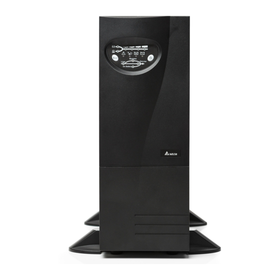
5. MAINTENANCE Normally, the life of battery is 3 years. But extreme operating condition and environment may shorten its life-span. To replace batteries, contact qualified personnel. When UPS has been unused for a period of time, the batteries will discharge slightly. - Page 24 6. PLACEMENT To stably install the UPS, the 2,3KVA must add stands to support themselves. The installation method is as shown below: Fig 6-1 Erect the UPS with supporting stands SHEET 24 TO 25...
-
Page 25: Troubleshooting
7. TROUBLESHOOTING Problem ON/TEST button is not pushed. Battery low shut down and utility is absent. UPS is not turned on. (No alarm, No LED lights) The rear panel input circuit breaker is tripped. (Button is tripped out) UPS fault. Batteries inside the UPS are not fully charged. -
Page 26: Fault Message
The exhaust fans and ventilation grills may be obstructed. UPS over temperature. The environment temperature exceeds 40 “FAULT”LED lights on, UPS failure. alarm beeps “OVERLOAD” lights on and buzzer Overloaded. beeps continuously. FAULT MESSAGE Following information indicates various symptoms. Use this information to determine what factors cause the problem . 1. -
Page 27: Communication Interface
8. COMMUNICATION INTERFACE The UPS provides RS-232 and Dry contact protocols in one D-sub 9 connector. Using proper UPS management software and cable, the UPS can be managed over LAN/intranet/internet environment. The pin assignment of the D-sub 9 connector is defined as follows: UPS TxD(typical RS-232 level) UPS RxD(typical RS-232 level) -
Page 28: Dry Contact
The RS-232 communication port provides the following functions: 1) Monitoring charger status 2) Monitoring battery status and condition 3) Monitoring inverter status 4) Monitoring UPS status 5) Monitoring the utility status 6) Providing the power switch function for computer to turn on/off the utility on schedule for power saving 7) Adjustable Transfer voltage The UPS data is provided at 2400 bps baud rate and made up of 8-bit, 1 stop-bit and no... - Page 29 Its major functions normally some or all of following: To broadcast a warning when power fails. To close the files before the battery is exhausted. To turn off the UPS computers. Some computers may have a special connector to link this communication port, or require a special plug-in card, or need a special UPS monitoring software.
-
Page 30: Technical Specifications
Replace、Battery Level、Load Level Buzzer RS232/Dry Contact Internal 40dBA 42dBA 0~40℃ 0%~--90%(Non-Condensing) UL/cUL TUV/GS FCC Class A(2,3KVA)/B(1KVA) CISPR PUB 22 Class B; TUV/EMC; CE IEEE 62.41 Category A Yes (Optional with Long Time) Yes (Optional) 140x363x242/mm 140x363x242/mm 140x422x373/mm 5.5x14.2x9.5/inch 5.5x14.2x9.5/inch 5.5x16.6x14.7/inch... - Page 31 SHEET 31 TO END...
Need help?
Do you have a question about the 3KVA and is the answer not in the manual?
Questions and answers