
Subscribe to Our Youtube Channel
Related Manuals for Taurus Ergo-X


Summary of Contents for Taurus Ergo-X
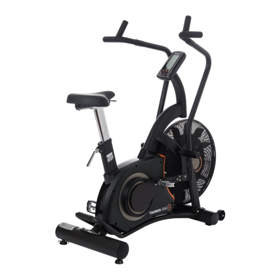
- Page 1 Assembly and Operating Instructions max. 160 kg ~ 45 Min. 72 kg L 124 | W 72 | H 144 CVEB2603.01.07 SKU: CVEB2603 Taurus Ergo-X...
- Page 2 ERGO...
-
Page 3: Table Of Contents
Content GENERAL INFORMATION Technical Data Personal Safety Set-Up Place ASSEMBLY General Instructions Scope of Delivery Assembly Further Information 2.4.1 Adjusting the seat post and saddle 2.4.2 Changing the batteries OPERATING INSTRUCTIONS Console Display Button Functions Turning on and off the equipment Programmes 3.4.1 Quick Start 3.4.2 Interval 20-10 Mode... - Page 4 ORDERING SPARE PARTS Serial Number and Model Name Parts List Exploded Drawing WARRANTY CONTACT ERGO...
- Page 5 With Taurus® fitness equipment, the focus is on what sport is all about: maximum performance! Therefore, the equipment is developed in close consultation with athletes and sports scientists.
- Page 6 ABOUT THIS MANUAL Please carefully read the entire manual before installation and first use. The manual will help you to quickly set up the system and explains how to safely use it. Make sure that all persons exercising with the equipment (especially children and persons with physical, sensory, mental or motor disabilities) are informed about this manual and its contents in advance.
-
Page 7: General Information
GENERAL INFORMATION Technical Data LCD display of training distance in km calories burnt in kcal heart rate (when using the hand sensors or a chest strap) Watt cadence (rotations per minute) speed in km/h training time in min target heart rate Resistance system: Air resistance system Total number of training programmes:... -
Page 8: Personal Safety
Personal Safety DANGER ⚠ Before you start using the equipment, you should consult your physician that this type of exercise is suitable for you from a health perspective. Particularly affected are persons who: have a hereditary disposition to high blood pressure or heart disease, are over the age of 45, smoke, have high cholesterol values, are overweight and/or have not exercised regularly in the past year. -
Page 9: Set-Up Place
Set-Up Place WARNING ⚠ Do not place the equipment in main corridors or escape routes. ⚠ CAUTION Choose a location in which to place the equipment such that there is enough free space/ clearance to the front, the rear and to the sides of the equipment. Make sure that you leave at least 30 cm on each side of the equipment and at least 15 cm in front of and behind the equipment as a training zone. -
Page 10: Assembly
ASSEMBLY General Instructions ⚠ DANGER Do not leave any tools, packaging materials such as foils or small parts lying around, as otherwise there is a danger of suffocation for children. Keep children away from the equipment during assembly. ⚠ WARNING Pay attention to the instructions attached to the equipment in order to reduce the risk of injuries. -
Page 11: Scope Of Delivery
Scope of Delivery The scope of delivery consist of the following parts. At the beginning, check whether all parts and tools belonging to the device are included in the scope of delivery and whether damage has occurred. In the event of complaints, the contractual partner must be contacted directly. CAUTION ⚠... -
Page 12: Assembly
Assembly Before assembly, take a close look at the individual assembly steps shown and carry out the assembly in the order given. NOTICE First loosely screw all parts together and check that they fit properly. Tighten the screws using the tool only when you are instructed to do so. Step 1: Assembly of front stabilizer Loosen both screws (J6) - Page 13 Step 3: Assembly of left and right arm bar & footrest Mount right, swinging handlebar (D2) with a spacer ring (J8) on the main frame (A). Mount foot support (G) then. Fix the footrest with the wrench and put an end USE TOOL cap (G2) on it.
- Page 14 Step 5: Assembly of pedals Loosen the screw (J7) from the crank (A8). Mount the right pedal (H2) on the crank (A8) and mount it with the Allen wrench and the wrench. Tighten the screw (J7) on the crank. Do the same on the left side. CAUTION ⚠...
- Page 15 Step 7: Assembly of the console Remove the pre-mounted screws from the console case (F). Connect the cable (E1) with the cable of the console (F). USE TOOL NOTICE Make sure that there are four AA batteries in the battery compartment.
-
Page 16: Further Information
Further Information 2.4.1 Adjusting the seat post and saddle STEP 1 Vertikal Adjustment (1) Pull the adjusting lever (A32) of the seat post up. Once you have found the desired saddle height, push the lever down again to lock the position. STEP 2 Horizontal Adjustment (2) Pull the adjusting lever (A55) -
Page 17: Operating Instructions
OPERATING INSTRUCTIONS NOTICE Familiarise yourself with all the functions and setting options of the device before starting training. Have the proper use of this product explained to you by a specialist. Console Display 20/10 10/20 INTERVAL CUSTOM TOTAL TIME CYCLE WATTS TIME TOTAL... - Page 18 Displays the rotations per minute RPM (UPM) Range: 0 – 15 to 200. SPEED Displays the current speed. Maximum speed 99.9 km/h or mph. Counts up the time from 00:00 to a maximum of 59:59 or counts down the time from the pre-set time to 00:00. TIME Target value for time can be set with the UP/DOWN buttons.
-
Page 19: Button Functions
Button Functions Pause or continue the training; hold pressed for two seconds to START change between kilometres and miles Stop the training; hold pressed for two seconds to reboot the console STOP at any time (TOTAL RESET) Reduce adjustable values (distance, calories, time, age); hold pressed DOWN for more than one second to reduce quicker the value;... -
Page 20: Turning On And Off The Equipment
Turning on and off the equipment When equipment turned on (insert batteries), the LCD displays lights up for two seconds (fig. 1), a long signal sounds. Then the wheel diameter is displayed in the DISTANCE window for a second (fig. 2). Then you get to the age setting. - Page 21 Fig. 8 Fig. 9 Fig. 10 Fig. 11 Fig. 12 Fig. 13 Fig. 14 Fig. 15 Fig. 16 Fig. 17...
-
Page 22: Programmes
Programmes You can choose from the following programmes: Quick Start Interval 20-10 Interval 10-20 Interval Custom Target Time Target Distance Target Calories Target HR After a five minutes training break a signal sounds and the console goes to the sleep mode. Pause the programme for 30 seconds by pressing START. - Page 23 TIME displays the training time, DISTANCE displays the distance, CALORIES displays the energy consumption – all values are displayed for 30 seconds. Watt, speed, and RPM change every five seconds between the displays AVG. & MAX (fig. 20, 21). NOTICE When a pulse signal is detected, heart rate, target heart rate, and BPM are displayed for 30 seconds.
-
Page 24: Interval 20-10 Mode
3.4.2 Interval 20-10 Mode In the standby mode, press INTERVAL 20/10 to start the programme. A countdown of three seconds starts. Then READY flashes and the training begins. A 20-seconds-interval begins. 20 seconds are counted down in the big window. Under the countdown, WORK flashes and signalises that you are in the training phase. -
Page 25: Interval 10-20 Mode
3.4.3 Interval 10-20 Mode In the standby mode, press INTERVAL 10/20 to start the programme. A countdown of three seconds starts. Then READY flashes and the training begins. A 10-seconds-interval begins. 10 seconds are counted down in the big window. Under the countdown, WORK flashes and signalises that you are in the training phase. -
Page 26: Interval Custom Mode
3.4.4 Interval Custom mode In the standby mode, press INTERVAL CUSTOM to start the programme. Set the desired number (1 to 99) of intervals (CYCLE) with the UP/DOWN buttons and confirm your settings with ENTER. Now you set the duration of the intensive intervals (WORK TIME) with the UP/DOWN buttons and confirm your settings with ENTER. - Page 27 Fig. 33 Fig. 34 Fig. 35 Fig. 36 Fig. 37 Fig. 38 Fig. 39 Fig. 40 CYCLE WORK TIME Interval Custom ENTER ENTER DOWN DOWN PAUSE START REST TIME STOP ENTER DOWN...
-
Page 28: Target Time Mode
3.4.5 Target Time Mode In the standby mode, press TAG TIME to start the programme. Set the target duration with the UP/DOWN buttons and confirm your settings with ENTER. Press START to start the programme. The training data Total Distance / Calories / Watts / Speed / RPM are counted up. Press START to pause the programme for 30 seconds at any time. -
Page 29: Target Distance Mode
3.4.6 Target Distance Mode In the standby mode, press TAG DISTANCE to start the programme. Set the target distance with the UP/DOWN buttons and confirm your settings with ENTER. Press START to start the programme. The training data Total Time / Calories / Watts / Speed / RPM are counted up. Press START to pause the programme for 30 seconds at any time. -
Page 30: Target Calories Mode
3.4.7 Target Calories Mode IIn the standby mode, press TAG CALORIES to choose the programme. Set the calorie target with the UP/DOWN buttons and confirm your settings with ENTER. Press START to start the programme. The training data Total Time / Distance / Watts / Speed / RPM are counted up. Press START to pause the programme for 30 seconds at any time. -
Page 31: Target Hr Mode
3.4.8 Target HR Mode ⚠ WARNING Your training equipment is not a medical device. The heart rate measurement of this equipment may be inaccurate. Various factors can affect the accuracy of the heart rate measurement. The heart rate measurement serves only as a training aid. In the standby mode, press TAG HEART RATE to choose the programme. -
Page 32: Storage And Transport
STORAGE AND TRANSPORT General Instructions ⚠ WARNING The storage location should be chosen so that improper use by third parties or children can be prevented. If your equipment does not have transportation wheels, the equipment must be disassembled before transportation. ࣑... -
Page 33: Troubleshooting, Care And Maintenance
TROUBLESHOOTING, CARE AND MAINTENANCE General Instructions ⚠ WARNING Do not make any improper changes to the equipment. CAUTION ⚠ Damaged or worn components may affect your safety and the life of the equipment. Therefore, immediately replace damaged or worn components. In such a case, contact the contract partner. -
Page 34: Maintenance And Inspection Calendar
Maintenance and Inspection Calendar To avoid damage from body sweat, the equipment must be cleaned with a damp towel (no solvents!) after each training session. The following routine tasks must be performed at the specified intervals: Part Weekly Monthly Display console Plastic covers Screws and cable connections Check pedals for tightness... -
Page 35: Recommended Accessories
RECOMMENDED ACCESSORIES To make your training experience even more efficient and pleasant, we recommend that you add suiting accessories to your fitness equipment. For exercise bikes this could for example be a floor mat, which makes your fitness equipment stand more securely and also protects the floor from sweat or silicone spray to keep moving parts in good shape. -
Page 36: Ordering Spare Parts
The exact position of this sticker is shown in the following illustration. Enter the serial number in the appropriate field. Serial number: Brand / Category: Taurus / exercise bike Model Name: Ergo-X Air Bike SKU: CVEB2603... -
Page 37: Parts List
Parts List Name Qty. Name Qty. Main Frame Washer Belt Wheel Φ360mm Outer Ring(R+L) Belt 690 J6 Samll Outer Ring(R+L) Magnetic (Φ15*7Mm) Axle M25*P1.5 Screw M8*35 Crank(R) Steel Fan Piece Crank(L) Plastic Strip Washer(Φ25*31*T2mm) Shaped Crank-L Screw M8*40Mm Shaped Crank-R Bearing 6005Zz Washer M5*Φ13*1T Adapter Sleeve... - Page 38 Steel-Fan Cover-L Screw Steel-Fan Cover-R Swing Handlebar (L) Decoration Cover-L Swing Handlebar (R) Decoration Cover-R Bearing 6202Zz Chain Cover(L) Screw M5*8Mm Chain Cover(R) C Clip S40 Sensor Housing Bearing 6203Zz Screw End Cap Screw Bearing 6003 Zz Screw M6*20Mm Spring Washer Φ17 Steel Console Tube Sensor Wire 450Mm...
-
Page 39: Exploded Drawing
Exploded Drawing J2*2 J5*6 A34*2 B3*2 B2*2 B1*2 B4*2 J6*8 J7*2 B5*2 B6*4 A36*2 C2*2 C1*2 A35*2 C3*2... -
Page 40: Warranty
WARRANTY Training equipment from Taurus® is subject to strict quality control. However, if a fitness equipment purchased from us does not work perfectly, we take it very seriously and ask you to contact our customer service as indicated. We are happy to help you by phone via our service hotline. - Page 41 Warranty Service Within the warranty period, equipment which develops faults as a result of material or manufacturing defects, will be repaired or replaced at our discretion. Ownership of equipment or parts of equipment which have been replaced is transferred to us. The warranty period is not extended nor does a new warranty period begin following repair or replacement under the warranty.
-
Page 42: Contact
CONTACT TECHNIK TEKNIK OG SERVICE TECHNIQUE & SERVICE �� �� �� +49 4621 4210-900 80 90 16 50 +33 (0) 189 530984 +49 4621 4210-945 +49 4621 42 10 933 �� +49 4621 4210-698 �� �� info@fitshop.dk info@fitshop.fr �� technik@sport-tiedje.de ��... - Page 43 LIVE FITNESS WEBSHOP AND SOCIAL MEDIA The Sport-Tiedje Group is Europe’s largest http://www.powerhouse-fitness.co.uk/ specialist for home fitness equipment with www.powerhouse-fitness.co.uk/blog/ currently 70 stores and one of the world’s most renowned online mail order companies for fitness equipment. https://www.facebook.com/powerhousefitness.co.uk Powerhouse Fitness is part of the Sport-Tiedje Group.
- Page 44 Exercise bike ERGO...
Need help?
Do you have a question about the Ergo-X and is the answer not in the manual?
Questions and answers