Table of Contents
Advertisement
Quick Links
User Manual
I1000-RH1 Series
3kW / 3.68kW / 5kW / 6kW
Single Phase, 2 MPPTs High Voltage Hybrid Inverter
150% DC input oversizing
Charging / discharging efficiency >97%
Support VPP / FFR function
Up to 6000W charging / discharging rate
Remote firmware upgrade & work
mode setting
EU standard certified by TUV Rheinland
Advertisement
Table of Contents

Related Manuals for Energy I1000-RH1 Series


Summary of Contents for Energy I1000-RH1 Series
- Page 1 User Manual I1000-RH1 Series 3kW / 3.68kW / 5kW / 6kW Single Phase, 2 MPPTs High Voltage Hybrid Inverter Up to 6000W charging / discharging rate 150% DC input oversizing Remote firmware upgrade & work Charging / discharging efficiency >97%...
-
Page 3: Table Of Contents
Content 1. About This Manual....................... 3 1.1 Applicability..........................3 1.2 Target group..........................3 1.3 Symbols used..........................3 2. Safety..........................3 2.1 General Safety..........................3 2.2 Important safety instructions...................... 3 2.3 Explanation of symbols....................... 5 3. Introduction......................... 5 3.1 Basic features..........................5 3.2 Work modes.......................... - Page 4 Notice This manual contains important safety instructions that must be followed during installation and maintenance of the equipment. Save the manual! IMPORTANT TO READ CAREFULLY AND KEEP FOR POSSIBLE CONSULTATIONS Copyright Declaration All rights to the content of this manual are owned by GS (Ningbo) ESS Technology Co , Ltd ( hereinafter called as ‘GS ESS Power’...
-
Page 5: About This Manual
1. About This Manual 1.1 Applicability Please read the product manual carefully before installation,operation or maintenance.This manual contains important safety instructions and installation instructions that must be followed during installation and maintenance of the equipment. I1000-RH1-3K-M1 I1000-RH1-3.68K-M1 I1000-RH1-5K-M1 I1000-RH1-6K-M1 1.2 Target group This manual is intended for qualified electrical technical personnel who are responsible for hybrid inverte installation and commissioning in the eneray storage system. - Page 6 Islanding effect is a special phenomenon that grid-connected PV system still supply power to the nearby grid when the voltage loss is happened in the power system. It is dangerous for maintenance personnel and the public. I1000-RH1 series inverter provide Active Frequency Drift(AFD) to prevent islanding effect.
-
Page 7: Explanationof Symbols
3. Introduction 3.1 Basic features The I1000-RH1 series hybrid inverters apply to PV energy storage system with PV modules, battery, loads and grid. The energy produced by PV system shall be used to optimize self-consumption, excess power charge battery and the rest power could be fed into the grid. Battery shall be discharged to support loads when PV power is insufficient to meet self-consumption. -
Page 8: Work Modes
3.2 Work modes The I1000-RH1 series hybrid inverter has the following work modes based on your configuration and layout conditions. Work mode: Self-use Priority: load>battery>grid Generated solar energy Load consumption Storage in battery Feed the excess solar energy into the grid Self-consumption of PV renewable energy is the highest priority. - Page 9 Work mode: Force time use Priority: battery>load>grid (when charging) Generated solar energy Storage in battery Load consumption Grid supply power when the battery capacity is not enough Priority: load>battery>grid (when discharging) Generated solar energy Load consumptio Self-use from battery Grid supply power when the battery capacity is not enough This mode applies the area that has electricity price between peak and valley.
-
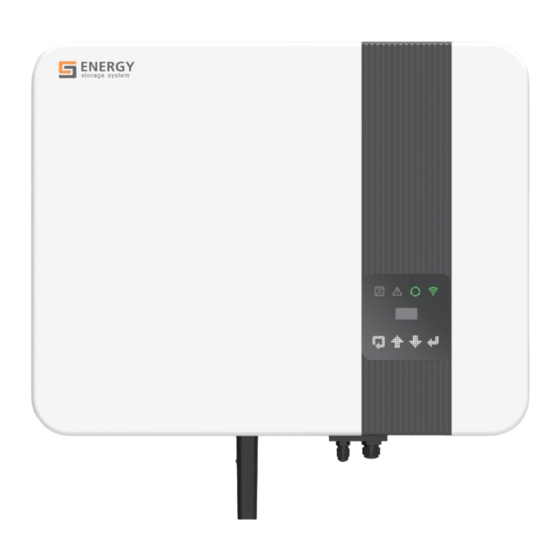
Page 10: Terminals
EPS output. 3.3 Terminals The I1000-RH1 series hybrid inverters apply to PV energy storage system with PV module, battery, loads and grid. The energy produced by PV system shall be used to optimize self-consumption, excesspowercharge battery and the rest power could be fed into the grid. -
Page 11: Dimension
Object Description Object Description DC switch SD port PV connector Communication port Battery connector EPS port WiFi or 4G or AC port Ethernet port Note: The DC switch is used to isolate PV strings. 3.4 Dimension 520mm 172mm 412mm Figure 3-3 Dimension 4. - Page 12 Model I1000-RH1-3K-M1 I1000-RH1-3.68K-M1 I1000-RH1-5K-M1 I1000-RH1-6K-M1 Output DC (Battery) Battery Type Lithium Battery Voltage Range [V] 80 ~ 450 Max. Charging / Discharging Current [A] Max. Charging / Discharging Power [W] 4500 / 3000 5000 / 3680 6000 / 5000 6000 / 6000 Communication Interface EPS Output Data (With Battery) EPS Rated Power [W]...
-
Page 13: Installation
5 Installation 5.1 Unpacking Check the delivery for completeness. Contact your dealer at once if anything is missing. Object Quantity Description I1000-RH1 series inverter Bracket Battery Connectors (1* positive, 1*negative) PV Connectors (2* positive, 2*negative) AC Terminal EPS Terminal 8P Pluggable Terminal Block... -
Page 14: Check For Transport Damage
It is recommended that the packaging should not be removed until the unit is located in the installation site. 5.2 Check for transport damage Check if the I1000-RH1 series inverter has some visible external damage, such as cracks in the housing or display please contact with your dealer if you find any damage. 5.3 Installation precaution... -
Page 15: Preparation
5.5 Preparation Tool Model Function Make sure the bracket is Level properly installed BOSCH HD18-2 Two- Drill holes on the wall Speed Hammer Dril Hammer Hanging the bracket KIM0 20V 1/2 Cordless Hanging the bracket Brushless Impact Wrench Set PV-AZM-410 Stripping plier for PV cable PV-CAM-22100 Crimping plier for PV cable... -
Page 16: Installation Steps
·Install the expansion tubes in the holes, and tight them. Install the wall bracket using the expansion screws in the screw package. Step2: Hang the I1000-RH1 series inverter on the wall bracket. ·Transportation of the inverter needs at least 2 people, each one needs to use the handles at the sides of the inverter. -
Page 17: Electrical Wiringconnection
5.7 Electrical WiringConnection The overview of the connection terminals of inverter please refer to Figure 3-2, and the wiring connections please refer to Figure 3-1 the PV energy storage system wiring diagram in chapter 3.1. System Connection Diagrams Note: This diagram is an example for Australian,South Africa and New Zealand grid system where neutral line can't be switched. - Page 18 ·Earth connection ·Communication connection 5.7.1 PV WiringConnection Before connecting PV strings to I1000-RH1 series hybrid inverter, please make sure requirements are followed as below : ·The total short- circuit current of PV string must not exceed inverter’s max DC current .
- Page 19 5.7.2 Battery Connection When you want to build a self-use storage system, the high voltage battery is a necessary part. The I1000-RH1 series inverter provides the necessary part of the interfaces to connect the battery. WARNING! Make sure you select the correct specification cables fo installation.
- Page 20 8.Fit the two connectors together until the connection audibly locks into place. 9. Check to make sure the connection is securely locked 10.Separating connectors 1). Insert the screwdriver into one of the four openings(□, A). 2). Leave the screwdriver in the opening. Pull the two connectors apart(□, B). NOTE: If the resistance to earth of each conductor of the PV array and battery system lower than the detection,the inverter will report Earth Fault Alarm.
- Page 21 BAT- 5.7.3 AC OutputConnection I1000-RH1 series inverters have already integrated RCMU (residual current monitoring unit) inside, however if an external RCD is and the groove on the housing engage perfectly until a ‘Click’ is heard or felt. required, a type A RCD with rated residual current of 30mA or higher is recommended.
- Page 22 2. Remove the cable jacket by 40 mm, and strip the wire insulation by 8 mm–15 mm. 3.Fully insert the conductors to the corresponding terminal and tighten the screws with the torque 0.8 Nm. Pull cables outward to check whether they are firmly installed. 4.Assemble the housing, the terminal block and cable gland (torque 4 Nm–5 Nm).
- Page 23 Temperature of Lead-acid battery Temp & GND—PIN7 and pin8 3. METER port Meter port PINS definition: Function METER-485A METER-485B The function of meter port same as pin1 & pin2 of ADD interface. Meter wiring diagram for Typical Energy Storage System...
- Page 24 Additional meter between the grid-connected inverters and I1000-RH1 series hybrid inverter is required. One I1000-RH1 series hybrid inverter can be connected maximum two On-Grid single-phase inverters, and in the system, the smart meter must be the EASTRON SDM230-Modbus.
-
Page 25: Inverter Manipulation
·Set sysswitch on the screen of the inverter to ‘Turn on’ Startup inverter: ·Inverter will start automatically when the PV panel generate enough energy or the battery is charged. ·Check the status of LED and LCD screen, first LED should be green and the LCD screen should display the main interface. -
Page 26: Operation Method
For maintenance or other service work, the inverter must be switched off. Proceed as follows to disconnect the inverter from the AC and DC power sources.Lethal voltages or damage to the inverter will follow if otherwise. ·Disconnect the external AC circuit breaker and secure it against reconnection. ·Rotate the DC switch to the "OFF"... -
Page 27: Lcd Operation
===Advanced*=== Battery Enter Password 0 0 0 0 Feature >New Password ===Advanced*=== =====Reset===== =====Reset===== =====Reset===== =Reset Errlogs= =Factory Reset= ==Reset Energy== Feature >Reset Energy Reset Energy Reset Energy New Password Reset Errlogs >Reset Errlogs Reset Errlogs >ESC< >ESC< >ESC< >Reset... - Page 28 A) Solar This status shows the real time PV parameters of the system. The input voltage, current and power of each PV input. Press up and down button to review the parameter. Press ‘ESC’ to return to status. =====Solar===== =====Solar===== =====Solar===== Vpv1: Ppv1:...
- Page 29 6.3.3. History The history function contains three aspects of the information: inverter yield, battery yield and error log. Press up and down to select, and review the data of system , press ’ESC’ to return to the Menu. ====History==== ===Yield Logs=== ===Yield Logs=== ===Yield Logs=== >Yield Logs...
- Page 30 D) PV Connection This function can set the mode of PV input. There are two modes for selection; Comm and Multi. The 'Comm' mode means single MPP tracking, 2 MPPT working together; 'Multi' means multi-MPP tracking, 2 MPPT work independently. Press up or down button to select and press 'OK' to confirm. =====Settings===== =PV Connection= =PV Connection=...
- Page 31 Grid codes National/Regional Grid Code Description Germany power Grid, meet Grid standards “VDE-AR-N-4105”. VDE4105-DE CEI0-21 Italy power Grid. For large interconnected power systems. Australia A e.g. all Australian networks other than Australia B/C and New Zealand. RD1699 Spain power Grid. EN50549 Default EN50549 Grid setting.
- Page 32 National/Regional Grid Code Description IEC61727-SL Sri Lanka power Grid, meet Grid standards “IEC61727”. Mexico Mexico power Grid, meet Grid standards “IEC61727 60HZ”. New Zealand All systems in New Zealand. Philippines Philippines power Grid, meet Grid standards “IEC61727 60HZ” spec IEC61727-SL-W Sri Lanka power Grid, Grid voltage range: 160-280V, Grid frequency range: 47-52HZ.
- Page 33 >Fac Lower Fast >Fac Upper Fast 47.00Hz 52.00Hz H) Export controla With this function the inverter can control the energy export to the grid. Press up or down button to change the export power. Press 'Ok' to confirm. ====On-Grid==== =Export Control= Safety >User Value...
- Page 34 ===Advanced*=== Enter Password Battery 0 0 0 0 Feature >New Password L) Reset Press up or down button to reset energy, reset errors or factory reset. Press ‘OK’ to confirm. ===Advanced*=== =====Reset===== ==Reset Energy== Feature >Reset Energy New Password Reset Errlogs >ESC<...
-
Page 35: App Remote Operation
6.3.5.System Switch Press up or down button to turn on or turn off the inverter. Press ‘OK’ to confirm. =====Menu===== ====SysSwitch==== History >Turn On Setting >SysSwitch 6.3.6. About This interface shows the information of the inverter, such as series number and software version. =====Menu===== =====About===== =====About=====... -
Page 36: Troubleshooting
I1000-RH1 series inverters. This section will help you narrow down the source of any problems you may encounter. Please read the following trouble-shooting steps. - Page 37 Inverter over current or battery over current or PV over current detected by hardware. · Disconnect PV, grid and battery, then reconnect. HW Protect Fault · Or seek help from us, if not go back to normal state. Grid is lost. Grid Lost Fault ·...
- Page 38 The sample value between master and slave is not consistent. · Disconnect PV, grid and battery, then reconnect. AD Sample Fault · Or seek help from us, if not go back to normal state. Over load in off grid mode. EPS Over Load ·...
- Page 39 The manager eeprom is fault. · Disconnect PV, grid and battery, then reconnect. Mgr EEPROM Fault · Or seek help from us, if not go back to normal state. The communication between meter and Inverter is interrupted. Meter Lost Fault ·...
-
Page 40: Maintenance
Battery temperature is high · Wait for 5 minutes, check again. BMS Protect TemHigh · Or seek help from us, if not go back to normal state. Battery temperature is low BMS Protect TemLow · Wait for 5 minutes, check again. ·... -
Page 41: Decommissioning
8 Decommissioning 8.1 Dementling the inverter ·Disconnect the inverter from DC input and AC output. ·Disconnect battery wiring. ·Wait for 5 minutes for de-energizing. ·Disconnect communication and optional connection wiring. ·Remove the inverter from the bracket. 8.2 Packaging If possible, please pack the inverter with the original packaging. If it is no longer available, you can also use an equivalent carton that meets the following requirements. - Page 43 GS(Ningbo)ESS technology Co.,Ltd Tel: +86-574-65292531 Web: www.gsmarte.com E-mail: service@gsmarte.com Add: No.2, Xingke West Road, Meiqiao Industrial Zone, Meilin Street, Ninghai County, Ningbo City, Zhejiang Province, China...
Need help?
Do you have a question about the I1000-RH1 Series and is the answer not in the manual?
Questions and answers