Table of Contents
Advertisement
Quick Links
Advertisement
Table of Contents

Related Manuals for Energy 5KTL-D3/G2


Summary of Contents for Energy 5KTL-D3/G2
- Page 1 Edition:1.0.0 USER MANUAL Three Phase Grid-tied PV String Inverter...
-
Page 2: Target Group
The illustration in this user manual is for reference only. This user manual is subject to change without prior notice. Target Group Inverters must be installed by professional electrical engineers who have obtained relevant qualifications. Scope Fan cooling series Fan cooling series Natural cooling series 22KTL-D3/G2 5KTL-D3/G2 12KTL-D3/G2P 6KTL-D3/G2 25KTL-D3/G2 15KTL-D3/G2P 8KTL-D3/G2 17KTL-D3/G2 30KTL-D3/G2 10KTL-D3/G2 20KTL-D3/G2... -
Page 3: Table Of Contents
CONTENTS 6. Startup/Shutdown Procedure Preface 6.1 Check before startup/shutdown procedure About This Manual 6.2 Startup/Shutdown steps Target Group 6.3 Shutdown procedure Scope Conventions 7. User Interface 8. Troubleshooting and Maintenance 1. Safety 8.1 Inverter Troubleshooting 1.1 Symbols Used 8.2 Maintenance 1.2 Safety Instruction 8.2.1 Routine Maintenance 2. -
Page 4: Safety
Safety Safety 1. Safety 1.2 Safety Instruction Before using the inverter, please read all instructions and cautionary markings on the unit and manual. Put the instructions where you can take them easily. Installation and maintenance of inverters must be performed by qualified personnel, in accordance with The inverter of us strictly conforms to related safety rules in design and test. -
Page 5: Product Introduction
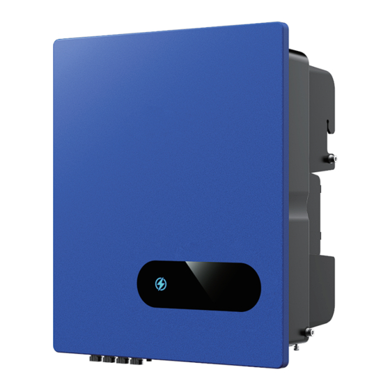
Product Introduction Product Introduction 2. Product Introduction Product Appearance 2.1 Overview The following is only for reference, specific please in kind prevail. The three-phase grid-tied PV inverter converts the DC generated by PV panels into three-phase alternating current and is delivered to the grid. 414.27mm 208.5mm This series inverter is an important part of PV system and it is suitable for household use,... -
Page 6: Unpacking And Storage
Product Introduction Unpacking and Storage Unpacking and Storage 3.1 Unpacking and Check Complete test and strict inspection shall be done before the inverter is sent out. When receiving the inverter, check that the packing materials are intact. After unpacking, examine the PV inverter and its fittings for damage and check that the deliverables are complete. -
Page 7: Storage Inverter
Installation Unpacking and Storage Installation Storage Inverter After checking the outer packing, move the PV inverter to the designated installation position horizontally. If the inverter is not used immediately, please keep the inverter in a specific environment according to the following requirements: 1. - Page 8 Installation Installation 4.1.2 Mounting Requirements Installation perspective schematic Mount the inverter vertically or tilted backward by max 15°. In order to facilitate the heat dissipation of the inverter. The wrong installation mode causes the inverter to be damaged or unable to NOTICE work properly.
-
Page 9: Mounting
Installation Installation 4.2 Mounting Step 1. Install the mounting bracket Step 2. Install the inverter. Install the inverter on the bracket accurately and tighten the screws at both sides, as shown in Step 5 and 1.The walls must be fireproof and non-flammable materials, othewise there Step 6. -
Page 10: Electrical Connection
Electrical Connection Electrical Connection Electrical Connection Grounding According to the EN50178 requirement, the right side of the device has a protective grounding connection. System Connection Be sure to connect the protection ground cable to this port when installing the inverter. The user can perform the ground connection according to the on-site condition. -
Page 11: Ac Connection
Recommended Value Unscrew the nut of the cover and thread the AC cable (5 wires) cross the nut, threaded sleeve and 5KTL-D3/G2, 6KTL-D3/G2, 8KTL-D3/G2 the cover. Then crimp the OT terminal and use heat shrink tubing or insulation tape for protection. -
Page 12: Dc Connection
Electrical Connection 5.3 DC Connection PV Strings configuration (for 5KTL-D3/G2, 6KTL-D3/G2, 8KTL-D3/G2, 10KTL-D3/G2 PV modules generate electric energy when exposed to sunlight and can create an and 10K1TL-D3/G2) electrical shock hazard. Therefore, when connecting the PV modules, shield them with opaque cloth and ensure that DC switches are OFF. - Page 13 Electrical Connection Electrical Connection Inverter models Inverter models 10K1TL-D3/G2P 10KTL-D3/G2P 12KTL-D3/G2 15KTL-D3/G2 15KTL-D3/G2P 17KTL-D3/G2 20KTL-D3/G2 22KTL-D3/G2 25KTL-D3/G2 30KTL-D3/G2 PV Strings PV Strings MPPT current 30A/30A 30A/30A 30A/30A 30A/30A 30A/30A 40A/30A MPPT current 15A/30A 15A/30A 15A/30A 15A/30A 166 panel 3 inputs 3 inputs 4 inputs 4 inputs...
- Page 14 Electrical Connection Electrical Connection 182 panel input configuration Before connecting the PV input to the inverter, ensure that the package meets the following electrical specifications. Inverter module Limit of each input open-circuit voltage Maximum allowable input terminal current 1100V Open-circuit voltage altitude derating curve of the inverter as shown in the following figure 2 inputs: using PV1 and PV3 3 inputs: using PV1, PV3 and PV4 1100V...
-
Page 15: Communication Connection
Electrical Connection Electrical Connection Communication Connection 5.3.2 PV Connection PV connection please refer to below. 5.4.1 Communication Mode Description You can use the following communication modes to implement communication: Bluetooth, WIFI, GPRS and RS485 which are described as follows. 8~10mm Limit buckle Positive Connector Click... - Page 16 Electrical Connection Electrical Connection 5.4.3 RS485 Connection The multiple inverter network and RS485 communication are as follows: ① Download the APP. Scan the QR code on the inverter to download the APP. Download the APP from the App Store or Google Play. Note: the APP should access some permissions such as inverter’s location.
-
Page 17: Startup/Shutdown Procedure
Startup/Shutdown Procedure User Interface Startup/Shutdown Procedure Shutdown Procedure It may be necessary to shut down the inverter sometimes during the daily use. If necessary, please Check before startup/shutdown Procedure follow the procedures: Check the following steps after installation. Supply Main Switch See if there’s any on site Items (The figure is only for reference) - Page 18 Leakage current HCT abnormal icon keeps on, or else, it blinks; when there is no voltage, the icon will be off. Icon stands for energy flow, when inverter is in normal status, the icon will be on, or else it will be off.
-
Page 19: Troubleshooting And Maintenance
1) Measuring three-phase voltages (L1-N, L2-N,L3-N) and check whether the imbalance is more than cause damage during the process. A6-Grid abnormal 30%. If yes, please contact energy company. (Only for three- 2) Measuring three-phase voltages at input and output sides of AC circuit breaker to check whether phase inverter) breaker is damaged. -
Page 20: Maintenance
Troubleshooting and Maintenance Troubleshooting and Maintenance 1. If the alarm occurs occasionally, the inverter can be automatically recovered. No extra action is C0-Internal power CF-Inverter 1. If the alarm occurs occasionally, the inverter can be automatically recovered. No action is required. needed. -
Page 21: Technical Specifications
Troubleshooting and Maintenance Technical Specifications Technical Specifications 10K1 10K-P 10K1-P MO DEL Input(PV) 1100V Max. PV power voltage (V) 620V Rated input voltage (V) 15A/15A 15A/15A 15A/15A 15A/15A 15A/15A 15A/30A 15A/30A 15A/30A 15A/30A Max. input current (A) 20A/20A 20A/20A 20A/20A 20A/20A 20A/20A 20A/40A... - Page 22 Technical Specifications MO DEL 15K-P Input(PV) Max. PV power voltage (V) 1100V Rated input voltage (V) 620V Max. input current (A) 30A/30A 30A/30A 30A/30A 30A/30A 30A/30A 40/30 A Max. short-circuit current (A) 40A/40A 40A/40A 40A/40A 40A/40A 40A/40A 50/37.5 A 180V/160V Starting voltage/Min.
Need help?
Do you have a question about the 5KTL-D3/G2 and is the answer not in the manual?
Questions and answers