
Subscribe to Our Youtube Channel
Related Manuals for WIKA FLC-608


Summary of Contents for WIKA FLC-608
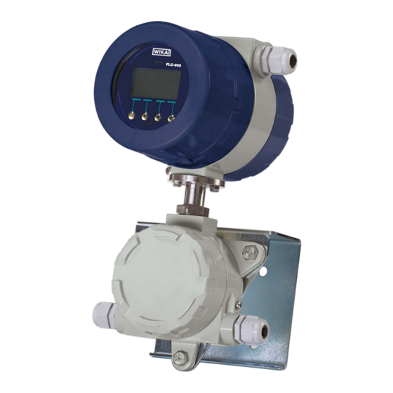
- Page 1 Operating Instructions Electromagnetic flow meter FLC-608 converter Electromagnetic flow meter FLC-608...
- Page 2 WIKA Operating Instructions electromagnetic flow Page 3 - 40 meter model FLC-608 Additional languages available on www.wika.com © 05/2014 WIKA Alexander Wiegand SE & Co. KG All rights reserved. WIKA ® is a registered trademark in various countries. Reference to trademark rights if necessary...
-
Page 3: Table Of Contents
4.3.5 Connection to the power supply ........23 WIKA Operating Instructions - Electromagnetic flow meter FLC-608... - Page 4 5.1.1 Software FLC-608 configuration ........
-
Page 5: Introduction
We recommend contacting Assistance WIKA Operating Instructions - Electromagnetic flow meter FLC-608... -
Page 6: Preliminary Notes
TEMP: minimum/maximum temperature of the working 1.7 Applications ■ conditions; FLC-608 is widely used for purposes in which it is important POWER S.: supply or battery voltage (FLC-608B); to measure the flow rate of electrically conductive liquids. ■ Hz: power supply frequency;... -
Page 7: Product Description
2.2 Available versions FLC-608 converter has been designed with the aim of The FLC-608 converter is available in 5 versions, and can fulfillment of all the requirements of modern water management cover all the different types of applications depending on the systems, through a flexible and hybrid electronics which, category of system to be monitored. -
Page 8: Converter Installation Types
2. Product description 2.3 Converter installation types 2.5 Power batteries Depending on the version of the FLC-608 converter, it can be The FLC-608B and FLC-608R converters are battery- installed in the system in two different ways: powered via a primary lithium battery as well as a rechargeable lithium battery. -
Page 9: Remote Data Reading
System. Fast download, data management, easy programming and an advanced self-diagnosis system, that automatically perform a wide range of essential checks, make the FLC-608 converter a highly efficient and irreplaceable tool for fluid detection in water management systems. A multi-level password system also allows controlled access to the data collected and guarantees confidentiality. -
Page 10: Technical Specifications
3. Technical specifications 3. Technical specifications 3.1 Overall dimensions 3.1.2 Version FLC-608B/R (Compact) The overall dimensions of single versions of the FLC-608 converters are shown below. 3.1.1 Version FLC-608A (Compact) Fig. 6: FLC-608B/R (Compact) dimensions Fig. 5: FLC-608A (Compact) dimensions... -
Page 11: Version Flc-608A (Remote)
3. Technical specifications 3.1.3 Version FLC-608A (Remote) 3.1.4 Version FLC-608B/R (Remote) Fig. 7: FLC-608A (Remote) dimensions Fig. 8: FLC-608B/R (Remote) dimensions WIKA Operating Instructions - Electromagnetic flow meter FLC-608... -
Page 12: Version Flc-608P (Remote)
3. Technical specifications 3.1.5 Version FLC-608P (Remote) 3.1.6 Version FLC-608I (Remote) Fig. 9: FLC-608P (Remote) dimensions Fig. 10: FLC-608I (Remote) dimensions WIKA Operating Instructions - Electromagnetic flow meter FLC-608... -
Page 13: Certificates And Approvals
NMI M 10 Meters intended for the metering of water in full flowing pipes Depending on the sensor connected to the FLC-608 converter, other certifications could be applicable; refer to the documentation on the specific sensor for more information: ATEX / IECEx... -
Page 14: General Technical Features
3. Technical specifications 3.3 General technical features The table below contains the technical data of the FLC-608 converter in all versions produced by Euromisure. Features FLC-608A FLC-608B FLC-608R FLC-608P FLC-608I Casing Aluminium Aluminium Aluminium Technopolymer IP68 IP68 IP68 IP54 IP54 90...264 Vac... - Page 15 CA22 – cables for sensors with four electrodes. ■ Pressure sensor 0...20 Bar; 1/8” GAS male, connector with factory installed fly coupling. Temperature sensor PT500: includes thermowell of 1/4”, length 50 mm, diameter 6 mm. WIKA Operating Instructions - Electromagnetic flow meter FLC-608...
-
Page 16: Accuracy
±2 % ± 2 mm/s Fig. 13 connected to insertion sensor NOTE The following accuracy class refers to the measurement conditions during the calibration at the Euromisure test benches: Fig. 11 Fig. 12 WIKA Operating Instructions - Electromagnetic flow meter FLC-608... -
Page 17: Installation
Do not move the flow meter with the lifting device if it is not in the original packaging (Fig. 16) or without an adequate support that ensures the required stability. Fig. 16 Fig. 14 WIKA Operating Instructions - Electromagnetic flow meter FLC-608... -
Page 18: Converter Positioning
Avoid exposing the converter to excessive vibrations. Use the remote version in case vibrations may occur. Fig. 21a: Relations between the conductivity of the liquid and the maximum allowed cable lenght for FLC-608 WIKA Operating Instructions - Electromagnetic flow meter FLC-608... -
Page 19: Flc-608R Compact Version: Installation Of The Solar Panel
4. Installation 4.3 Electrical connection NOTE In order to properly connect electrical elements of the FLC-608 converter to the power supply, and to the junction box (in Remote version), please refer to the wiring diagram shown in paragraph 4.3.1 (Fig. 23). -
Page 20: Connection To The Sensor
Fig. 24: Cables and connection terminals identification The FLC-608 converter can be installed on a wall or on a pole by using the brackets supplied with the Remote version CAUTION! as shown in figures 19 and 20. -
Page 21: Connection Options I/O
The connected instrument (PLC/external pulse counter) is an detect the pulses. The FLC-608 acts as a digital switch (logical active digital input which supplies voltage required to detect level). Maximum voltage: 5-30 Vdc; maximum electrical the pulses. - Page 22 Fig. 31 Active (FLC-608A/P/I) The receiver 4…20 mA connected to the instrument is a passive milliamp-meter; the internal FLC-608 24 Vdc power supply must be connected as shown in Figure 32. Loop voltage 24 Vdc; maximum impedance 800 Ω. Fig. 32 Fig.
-
Page 23: Electrical Grounding Of The Converter
Absent or incorrect grounding will result in unpredictable failure (Fig. 34a). In the FLC-608 Remote version, the sensor and the converter must be grounded using two separate wires (Fig. 34b). Avoid placing the signal and power cables close together to minimize interference. -
Page 24: Flc-608 Converter Programming
5.1.1 Software FLC-608 configuration The configuration of the FLC-608 converter can be performed Install the FLC-608 software on the PC, run the program, in three different ways: connect the unit to the PC. In case you are using a battery-... -
Page 25: Converter Password
NET – Net totalizer. ▶ Date, time, temperature and pressure indicator (the Figure 42 shows the main screen of the WIKA FLC-608 latter available with optional module). software properly connected to the converter. By accessing To choose the required value simply click the button that... -
Page 26: 5.2.2 Status Icons Identification And Description
MAX flow rate ALARMS threshold MENU: MIN flow rate PREFERENCES ■ threshold COUNTERS ■ PARAMETERS ■ EMPTY PIPE ■ THRESHOLD OTHER ■ MEMORY ■ Every first-level item allows access to their own submenu. WIKA Operating Instructions - Electromagnetic flow meter FLC-608... -
Page 27: Menu Items Description
Valid only for battery-powered versions FLC-608B/R; allows to select the measuring time of the system among 10/15/30/45/60/120/180/240/300/360/420/480 seconds. WARNING! Factory set time is 45 seconds. Any reduction of this factor will affect battery life when using the FLC-608B in battery mode. WIKA Operating Instructions - Electromagnetic flow meter FLC-608... - Page 28 0,45359 Kg ft³, cubic feet 28,31685 m³ acre-foot 1233,4818 m³ LANGUAGE Allows to choose one of the following menu languages: ENGLISH ■ ITALIANO ■ ESPAÑOL ■ PORTUGUÊS ■ FRANÇAIS ■ WIKA Operating Instructions - Electromagnetic flow meter FLC-608...
-
Page 29: Menu Counters
Various counters with the FLC-608 converter are available: two positive (total and partial) and two negative (total and partial). Only partial counters can be set to zero. To set the counters to zero from the FLC-608 software, access the screen “READ” and press the button “ZERO”... - Page 30 It allows the setting of the local power supply frequency (50 Hz o 60 Hz) in order to minimize interference. To read and change the filter values from the FLC-608 software program, access the screen “FILTERS” (Fig. 46) and change the filter values within indicated range.
-
Page 31: Menu I/O
Reverse flow rate (off/on) In case of negative flow, this function will enable/disable the pulses from the pulse output. Active pulse output Select to disable the frequency output and activate the pulse output (factory condition). WIKA Operating Instructions - Electromagnetic flow meter FLC-608... - Page 32 Fig. 47: Example of connection for the Programmable Output PROGRAMMABLE OUTPUT LOGIC It is possible to change the logic of the programmable output by choosing between NO/NC – normally open, normally closed. WIKA Operating Instructions - Electromagnetic flow meter FLC-608...
-
Page 33: Menu Other
DIAGRAM Displays the diagram of the measured flow rate. SIMULATION FLC-608 converter has an integrated flow simulator which checks and sets the pulse output to any connected device system. NOTE When the flow simulator is being used, the counter values are not increased. - Page 34 To access the selection of the three passwords that you want to change (L1,L2,L3), the Level 3 password is required. NEW BATTERY After replacing the battery pack, select “new battery” to confirm the replacement. WIKA Operating Instructions - Electromagnetic flow meter FLC-608...
-
Page 35: Maintenance
Connect the battery pack (see 1, Fig. 51) to the electronic board of the converter (see 2, Fig. 51) by inserting the 5-ways connector (see 3, Fig. 51) to the relative counterpart. WIKA Operating Instructions - Electromagnetic flow meter FLC-608... - Page 36 O-ring seal to guarantee the insulation. Step 5 Only in case of battery replacement, confirm the replacement by clicking the item “new battery” accessible from the menu “MEMORY.” WIKA Operating Instructions - Electromagnetic flow meter FLC-608...
-
Page 37: Troubleshooting
7.1 Malfunctioning and possible solutions The following table summarizes the possible malfunctions that may occur during the use of the FLC-608 converter, for which the possible causes and solutions to be adopted in order to restore correct operation of the flowmeter are listed. -
Page 38: Alarm Messages Solution
Supply voltage out of operating range. ■ Check the power supply network. Power supply voltage Move the antenna to a more favorable position. Low or missing GSM signal. ■ Check the antenna connection. Low GSM signal WIKA Operating Instructions - Electromagnetic flow meter FLC-608... -
Page 39: Dismounting, Return And Disposal
WARNING! Strictly observe the following when shipping the instrument: All instruments delivered to WIKA must be free from any kind of hazardous substances (acids, bases, solutions etc.). When returning the instrument, use the original packaging or a suitable transport packaging. - Page 40 WIKA Instruments Ltd via Borghisani 4 Unit 6 and 7 Goya Business park 26035 Pieve San Giacomo (CR) - Italy The Moor Road Telefon (+39) 0375 6404 Sevenoaks E-Mail salesflow.it@wika.com Kent www.wika.com TN14 5GY WIKA Operating Instructions - Electromagnetic flow meter FLC-608...
Need help?
Do you have a question about the FLC-608 and is the answer not in the manual?
Questions and answers