
Related Manuals for WIKA FLC-2300


Summary of Contents for WIKA FLC-2300
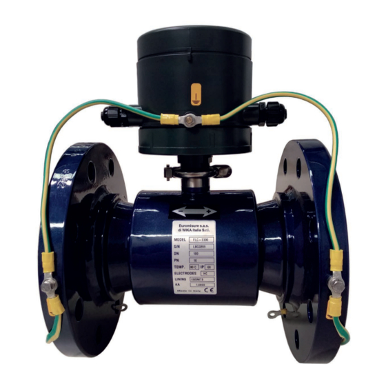
- Page 1 Operating Instructions Electromagnetic flow meters sensor bodies Electromagnetic flow meter FLC-2300...
- Page 2 WIKA Operating Instructions - Electromagnetic flow Page 3 - 38 meter sensors Additional languages available on www.wika.com Prior to starting any work, read the operating instructions! Keep for later use! WIKA Operating Instructions - Electromagnetic flow meter sensors...
-
Page 3: Table Of Contents
......20 4.6 Pipes equipped with cathodic protection..... 20 WIKA Operating Instructions - Electromagnetic flow meter sensor bodies... - Page 4 11.1 Repair request form......36 12. Product disposal WIKA Operating Instructions - Electromagnetic flow meter sensor bodies...
-
Page 5: Introduction
We recommend contacting Assistance Service for clarifications in this regard for more precise instructions. WIKA Operating Instructions - Electromagnetic flow meter sensor bodies... -
Page 6: Product Identification
DN: Nominal diameter [inches or mm]; the type of converter and be able to complete ■ PN: Nominal pressure; the repair request form attached to this manual. ■ TEMP.: Maximum liquid temperature for process ■ completion; WIKA Operating Instructions - Electromagnetic flow meter sensor bodies... -
Page 7: Applications
Mines District measure Drinking or wastewater measurement Tax measures Industrial processes Flow profiling Leakage detection Building sector Fire-fighting systems Refrigeration systems Pumping stations Water treatment Verification of flow meters on site WIKA Operating Instructions - Electromagnetic flow meter sensor bodies... -
Page 8: Product Description
FLC-1000EL - Wafer ■ «v». FLC-1100J - Wafer in plastic material ■ 2.2.3 Insertion sensors FLC-1222 ■ FLC-2660 ■ FLC-2770 ■ Electromotive force (proportional to the speed) Electrodes Magnetic field Coils WIKA Operating Instructions - Electromagnetic flow meter sensor bodies... -
Page 9: Type Of Installation Of The Sensor
Flanged Sensors Wafer Sensors Insertion Sensors COMPACT installation The sensor is connected directly to the related converter. SEPARATE installation [remote] The sensor is connected to the converter by specific power/signal cables. WIKA Operating Instructions - Electromagnetic flow meter sensor bodies... -
Page 10: Installation
Do not move the flow meter with the lifting device if it is not in the original packaging (Fig. 4) or without adequate support that ensures the required stability. Fig. 4 Fig. 2 WIKA Operating Instructions - Electromagnetic flow meter sensor bodies... -
Page 11: General Installation Requirements
Fig. 6: Avoid vibrations Install a suitable anti-vibration protection if vibrations occur. Fig. 9: Avoid direct exposure to sunlight Fig. 7: Installation with anti-vibration protections WIKA Operating Instructions - Electromagnetic flow meter sensor bodies... -
Page 12: Operating Temperatures
Coating in PTFE (remote) +130 +266 Coating in PTFE (compact) +176 Coating in PTFE (separate high temperature) +180 +356 FLC-1100J +176 Insertions +176 Fig. 11: Correct position Fig. 12: Incorrect position WIKA Operating Instructions - Electromagnetic flow meter sensor bodies... -
Page 13: Important Guidelines For Correct Installation
Fig. 17: √ This installation secures the sensor full of liquid. Fig. 14: Installation of Insertion Sensors on U-shaped tube Fig. 18: X This installation DOES NOT guarantee a pipe full of liquid. WIKA Operating Instructions - Electromagnetic flow meter sensor bodies... - Page 14 Fig. 23: Avoid negative pressure X DO NOT install the sensor on vertical pipes with a free outlet or at the highest point of the pipe system. Fig. 20: Incorrect position Fig. 24: Incorrect installation WIKA Operating Instructions - Electromagnetic flow meter sensor bodies...
-
Page 15: Installation
Insertion meters can also be installed horizontally. Fig. 31: Incorrect installation √ The pipe must be the support for the flow meter. Fig. 27: Correct position Fig. 28: Incorrect position Fig. 32: Correct installation WIKA Operating Instructions - Electromagnetic flow meter sensor bodies... -
Page 16: Tightening Torque
PTFE Ebonite OR NBR 4xM12 4xM12 4xM16 4xM16 4xM16 4xM16 8xM16 8xM16 8xM16 8xM16 8xM20 8xM20 12xM20 12xM20 12xM24 12xM20 12xM24 16xM20 16xM24 20xM24 20xM24 20xM27 20xM27 24xM30 28xM30 1000 28xM35 WIKA Operating Instructions - Electromagnetic flow meter sensor bodies... -
Page 17: Underground Installations
In this case, the flow meter could go into the air will be released from the pipe, maximizing the system Error mode (see the related converter manual). capacity. WIKA Operating Instructions - Electromagnetic flow meter sensor bodies... -
Page 18: Instructions For Diameter Reduction
These valves ensure that the largest formation, especially if the meter has a reduced volumes of air are released quickly and section; this condition must be absolutely avoided. effectively while filling the pipe. WIKA Operating Instructions - Electromagnetic flow meter sensor bodies... -
Page 19: Potential Equalization
Fig. 47: Grounding of sensor on metal pipes Fig. 44: Separate version grounding connection NOTE In the case of metal pipes with an insulating coating, follow the instructions for plastic pipes. WIKA Operating Instructions - Electromagnetic flow meter sensor bodies... -
Page 20: Metal Pipes With Insulating Adapters
Fig. 50: Grounding of the sensor on protected cathodic pipes Insulating washers Insulating gaskets Metal grounding ring Sensor insulating coating Fig. 49: Grounding of the sensor on metal and plastic pipes (with grounding rings) WIKA Operating Instructions - Electromagnetic flow meter sensor bodies... -
Page 21: Electrical Connection
Refer to the manual of the relative converter for more information. WIKA Operating Instructions - Electromagnetic flow meter sensor bodies... -
Page 22: Separation Cables
Characteristics and dimensions of the pressure transducer supplied by Euromisure may vary depending on the model of the connected converter. Fig. 56b: Pressure tap Fig. 56a: Pressure tap WIKA Operating Instructions - Electromagnetic flow meter sensor bodies... -
Page 23: Insertion Meters
Where R is the radius of the passage section and D internal diameter of the same. Fig. 57: Operating principle Fig. 59 WIKA Operating Instructions - Electromagnetic flow meter sensor bodies... -
Page 24: Care Of The Device
If the electrodes are rotated by an angle φ, d’≠ d and an error in the measurement will, therefore, be introduced. WIKA Operating Instructions - Electromagnetic flow meter sensor bodies... -
Page 25: Flc-1222
The FLC-1222 sensor is equipped with a safety chain to prevent the rapid exit of the sensor rod, which could be dangerous for the operator. In any case, the installation, assembly, and disassembly of the sensor must be carried out exclusively by expert and trained personnel. WIKA Operating Instructions - Electromagnetic flow meter sensor bodies... -
Page 26: Calculation Of The Insertion Depth
Where: L = Flow meter length according to the table of Fig. 63a; ■ = Internal pipe diameter; ■ S = Thickness of the pipe, including possible coating. ■ Fig. 64 WIKA Operating Instructions - Electromagnetic flow meter sensor bodies... -
Page 27: Installation Of The Sensor
(30 ft-lb). the head with the electrodes from to the pipe axis. The alignment hitting the valve. precision must be within ±2°. Use PTFE tape to ensure the tightness of the thread. WIKA Operating Instructions - Electromagnetic flow meter sensor bodies... -
Page 28: Installation On Non-Metallic Pipes Using A Saddle Bracket
The diameter of the hole must be Ø 25±1 mm. saddle bracket. Use PTFE tape to ensure the tightness of the thread. 7.3.5 Flow meter grounding Fig. 75: FLC-1222 grounding WIKA Operating Instructions - Electromagnetic flow meter sensor bodies... -
Page 29: Flc-2660
Ex mb IIC T6...T4 Gb Ex mb IIIC T85 °C...T135 °C Db -20 °C ≤ Ta ≤ +60 °C Wetted materials Sensor body SS316 Measuring head Electrodes SS316L Safety ring SS304 Sensor body Brass O-Ring WIKA Operating Instructions - Electromagnetic flow meter sensor bodies... -
Page 30: Calculation Of The Insertion Depth
M: Where: L = Flow meter length = 367 mm; ■ = Internal pipe diameter; ■ S = Thickness of the pipe, including possible coating. ■ Fig. 77 WIKA Operating Instructions - Electromagnetic flow meter sensor bodies... -
Page 31: Installation Of The Sensor
(with an accuracy of ± 2°) and the in place. insertion depth. WIKA Operating Instructions - Electromagnetic flow meter sensor bodies... -
Page 32: Flow Meter Grounding
Hot-Tap functionality. The maximum pressure at which the meter can operate is 25 bar. Fig. 84: FLC-2660 grounding Fig. 85: FLC-2770 dimensions and features Flange dimensions UNI - EN1092 ANSI150 98.4 WIKA Operating Instructions - Electromagnetic flow meter sensor bodies... -
Page 33: Calculation Of The Insertion Depth
= Sub-flange length of the flow meter; ■ = Internal pipe diameter; ■ 1200…1600 S = Thickness of the pipe, including possible coating. ■ 1700…2100 2200…2500 7.5.2 Calculation of the insertion depth Fig. 86 WIKA Operating Instructions - Electromagnetic flow meter sensor bodies... -
Page 34: Installation Of The Sensor
Insert the fixing bolts to secure the sensor Tighten the bolts to block the position of the Insert the sensor in the flanged sleeve, flange to the flanged sleeve attached to the sensor. aligning the holes. pipe. WIKA Operating Instructions - Electromagnetic flow meter sensor bodies... -
Page 35: Flow Meter Grounding
In the case of ebonite-coated Euromisure flow 9. Troubleshooting For the Troubleshooting section (Problems / Causes / Solutions), please refer to the instruction manual of the converter associated with the specific sensor. WIKA Operating Instructions - Electromagnetic flow meter sensor bodies... -
Page 36: Certifications And Technical Features
WIKA Operating Instructions - Electromagnetic flow meter sensor bodies... -
Page 37: Product Disposal
Unauthorized disposal of the product by the user results in the application of the administrative sanctions provided for by applicable law. Fig. 93: Crossed-out wheelie bin symbol WIKA Operating Instructions - Electromagnetic flow meter sensor bodies... - Page 38 For WIKA branches worldwide, visit our website www.wika.com Euromisure s.a.s di WIKA Italia S.r.l via Borghisani 4 26035 Pieve San Giacomo (CR) - Italy Telefon (+39) 0375 6404 E-Mail salesflow.it@wika.com www.wika.com WIKA Operating Instructions - Electromagnetic meter sensor bodies...
Need help?
Do you have a question about the FLC-2300 and is the answer not in the manual?
Questions and answers