Table of Contents
Advertisement
Quick Links
Advertisement
Table of Contents

Related Manuals for NPI ION-01M


Summary of Contents for NPI ION-01M
- Page 1 OPERATING INSTRUCTIONS AND SYSTEM DESCRIPTION FOR THE ION-01M IONSENSITIVE AMPLIFIER MODULE FOR EPMS SYSTEMS VERSION 1.4 npi 2014 npi electronic GmbH, Bauhofring 16, D-71732 Tamm, Germany Phone +49 (0)7141-9730230; Fax: +49 (0)7141-9730240 support@npielectronic.com; http://www.npielectronic.com...
-
Page 2: Table Of Contents
2.7. Technical Data ......................5 EPMS-07 and EPMS-H-07 ..................5 EPMS-E-07 ........................5 3. ION-01M ..........................6 3.1. Components of the ION-01M ..................6 3.2. System Description ...................... 6 3.3. Description of the Front Panel and Operation ............. 7 3.4. Headstage ........................10 3.5. -
Page 3: Safety Regulations
VERY IMPORTANT: Instruments and components supplied by npi electronic are NOT intended for clinical use or medical purposes (e.g. for diagnosis or treatment of humans), or for any other life-supporting system. npi electronic disclaims any warranties for such purpose. Equipment supplied by npi electronic must be operated only by selected, trained and adequately instructed personnel. -
Page 4: Epms-07 Modular Plug-In System
2.1. General System Description / Operation The npi EPMS-07 is a modular system for processing of bioelectrical signals in electrophysiology. The system is housed in a 19” rackmount cabinet (3U) has room for up to 7 plug-in units. The plug-in units are connected to power by a bus at the rear panel. -
Page 5: System Grounding
ION-01M User Manual _______________________________________________________________________________________________________________ Figure 1: PWR-03D front panel view Figure 2: PWR-03D rear panel view Note: This power supply is intended to be used with npi EPMS-E systems only. 2.6. System Grounding EPMS-07 The 19" cabinet is grounded by the power cable through the ground pin of the mains connector (= protective earth). -
Page 6: Ion-01M
3.2. System Description The ION-01M amplifier is a plug-in unit for the npi EPMS-07 modular system. It was designed for recording signals from ionsensitive microelectrodes. The system consists of a main amplifier system and a small headstage with differential input. -
Page 7: Description Of The Front Panel And Operation
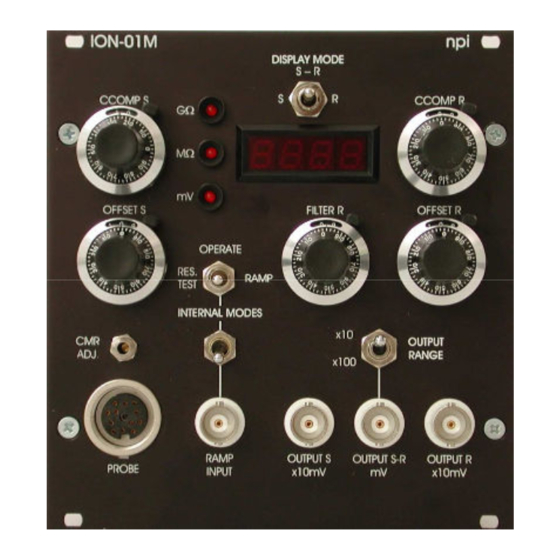
ION-01M User Manual _______________________________________________________________________________________________________________ 3.3. Description of the Front Panel and Operation Figure 4: Front panel view of the ION-1M In the following description of the front panel elements each element has a number that is related to that in Figure 4. The number is followed by the name (in uppercase letters) written on the front panel and the type of the element (in lowercase letters). - Page 8 ION-01M User Manual _______________________________________________________________________________________________________________ CCOMP R potentiometer 10-turn potentiometer for setting the capacity compensation for the reference electrode. OFFSET R potentiometer 10-turn potentiometer for setting the OFFSET compensation for the reference electrode; range: ±100 mV. FILTER R potentiometer 10-turn potentiometer for setting the low pass FILTER for the reference electrode. The low pass filter improves AC CMR;...
- Page 9 ION-01M User Manual _______________________________________________________________________________________________________________ (13) OFFSET S potentiometer 10-turn potentiometer for setting the OFFSET compensation for the sample electrode; range: ±100 mV. (14) CCOMP S potentiometer 10-turn potentiometer for setting the capacity compensation for the sample electrode. (15) GΩ / MΩ / mV LEDs LEDs indicating the unit of display #17.
-
Page 10: Headstage
ION-01M User Manual _______________________________________________________________________________________________________________ 3.4. Headstage Figure 5: headstage electrode mount connector for the sample (ionsensitive) electrode, S connector for the reference electrode (1 mm jack), R connector for ground, GND 3.5. Test resistors Two resistors are provided to test the amplifier. Both inputs can be connected to a function generator via a voltage divider (/1000) which is also supplied. -
Page 11: Electrode Connection
ION-01M User Manual _______________________________________________________________________________________________________________ 3.6. Electrode connection Figure 7: Equivalent circuit of ionsensitive measurement The principle of operation is shown in Figure 7. Two electrodes, an “active” ion exchanger sample electrode (+) and a reference electrode (-), which are connected to high impedance buffers (input resistance better than 10 Ω) in the headstage, are required for detecting signals... -
Page 12: Literature
ION-01M User Manual _______________________________________________________________________________________________________________ 4. Literature Polder, H.R., M. Weskamp, K. Linz and R. Meyer Voltage-Clamp and Patch-Clamp Techniques, Chapter 3.4, pp. 272-323 in Dhein, St.; Mohr, F.W.; Delmar, M. (Eds.) Practical Methods in Cardiovascular Research, Springer Heidelberg 2004 Schwarz, W. and J. Rettinger (2003) Foundations of Electrophysiology Second Edition, Shaker Verlag Aachen, 2003 Voipio, J., M.
Need help?
Do you have a question about the ION-01M and is the answer not in the manual?
Questions and answers