
Related Manuals for INOXPA INNOVA T


Summary of Contents for INOXPA INNOVA T
- Page 1 INSTALLATION, SERVICE AND MAINTENANCE INSTRUCTIONS TANK BOTTOM MIXPROOF VALVE INNOVA T Original Instructions 10.252.30.05EN (0) 2023/10...
- Page 2 INOXPA S.A.U. Telers, 60 17820 - Banyoles (Spain) hereby declare under our sole responsibility that the TANK BOTTOM MIXPROOF VALVE Machine: INNOVA Model: Type: DN 40 - DN 100 / OD 1½’’ - OD 4’’ Size: IXXXXXXXXX IXXXXXXXXX Serial number:...
- Page 3 INOXPA S.A.U. Telers, 60 17820 - Banyoles (Spain) hereby declare under our sole responsibility that the TANK BOTTOM MIXPROOF VALVE Machine: INNOVA Model: Type: DN 40 - DN 100 / OD 1½’’ - OD 4’’ Size: IXXXXXXXXX IXXXXXXXXX Serial number:...
-
Page 4: Table Of Contents
9. Technical Specifications 9.1. Valve ..................................24 9.2. Actuator ................................24 9.3. Materials ................................24 9.4. Sizes available ..............................24 9.5. Weights ................................25 9.6. Dimensions ................................ 25 9.7. Exploded drawing and parts list ........................26 INOXPA S.A.U. 10.252.30.05EN · (0) 2023/10... -
Page 5: Generalities
INOXPA. The non-compliance of the prescribed indications in this manual means misuse of this gear on the technical side and the personal safety and this exempts INOXPA of all responsibility in case of ac- cidents and personal injuries and/or property damage. Also, excluded from the warranty all break- downs caused by improper use of the gear. -
Page 6: Safety
Important instruction to prevent damage to the equipment and/or its function 3.2. GENERAL SAFETY INSTRUCTIONS Read the instruction manual carefully before installing and starting the valve. Contact INOXPA in case of doubt. 3.2.1. During installation Always take into account the Technical Specifications of chapter 9. -
Page 7: General Information
The valve can be cleaned to any level, depending on the process needs. 4.2. APPLICATION The tank bottom mixproof valve is designed to be installed in tanks and vats for hygienic applications. INOXPA S.A.U. 10.252.30.05EN · (0) 2023/10... -
Page 8: Installation
5. Installation 5.1. RECEPTION OF THE VALVE INOXPA is not liable for any deterioration of the material caused by its transport or unpac- king. When receipt the valve, check to see whether all the parts listed on the delivery slip are present:... - Page 9 DN 50, OD 2’’ DN 80 OD 2½’’ DN 100, OD 4’’ DN 65 Seals HNBR EPDM Material 1.4404 (AISI 316L) Connection Weld Standard pipe Body configuration 1 body Type tank bottom mixproof valve Product family INNOVA valve INOXPA S.A.U. 10.252.30.05EN · (0) 2023/10...
-
Page 10: Location
During installation, the valve avoids using excessive force and pay special attention to: - vibrations that may be produced on the facility, - hermal dilation that the pipe may undergo when hot fluids are circulating, - the weight that the pipe can support, - excessive welding current. INOXPA S.A.U. 10.252.30.05EN · (0) 2023/10... -
Page 11: Checking And Review
DN 100 / OD 4’’ 5.9. CONNECTING THE AIR TO ACTUATOR The valve configuration is normally closed (NC). Never disassemble the clamps of the valve without reading the instructions carefully since the actuator contains a spring inside it with an applied load. Valve and actuator assembly and disassembly only should be done by qualified persons. INOXPA S.A.U. 10.252.30.05EN · (0) 2023/10... -
Page 12: Connecting The Air To Actuator
Installation 5.10. CONNECTING THE AIR TO ACTUATOR To perform the air connection to the actuator: - connect and check the air connections (G 1/8’’ thread for tubing Ø6 mm) with thread in accor- dance with double-effect or simple effect needs. mind the quality of the compressed air according to the specifications described in chapter 9. Technical Specifications. Air connections G 1/8’’ thread INOXPA S.A.U. 10.252.30.05EN · (0) 2023/10... -
Page 13: Start-Up
ATTENTION Do not modify the operating parameters for which the valve has been designed without prior written authorisation from INOXPA. Do not touch the moving parts of the coupling between the actuator and the valve when the actuator is connected to the compressed air supply. -
Page 14: Operating Problems
Product pressure exceeds the actuator specifica- • Reduce the product pressure tions • Excessive product pressure in body Reduce the product pressure • Loss of seal (vibrations) Tighten loose parts • • Insufficient time for impulses Adjust cleaning time in control system Increase the compressed air pressure • Insufficient air pressure INOXPA S.A.U. 10.252.30.05EN · (0) 2023/10... -
Page 15: Maintenance
See the following table. NLGI DIN SEAL COMPONENT LUBRICANT 51818 Class HNBR / FPM klübersynth UH 1 64-2403 EPDM / HNBR / FPM PARALIQ GTE 703 INOXPA S.A.U. 10.252.30.05EN · (0) 2023/10... -
Page 16: Cleaning
Clean the entire interior and exterior of the valve before starting disassembly and assem- bly tasks. 8.3.2. Automatic SIP (sterilization-in-place) Sterilization with steam is applied to all equipment including the pipping. INOXPA S.A.U. 10.252.30.05EN · (0) 2023/10... -
Page 17: Disassembly And Assembly The Valve
17 mm Bottom shaft 8 mm 12 mm - 17 mm crescent spanner to separate the lantern from the actuator, - 2 mm Allen wrench to loosen the sleeve bolt of the valve, - appropiate tool (not piercing) to mount the seat seals. INOXPA S.A.U. 10.252.30.05EN · (0) 2023/10... - Page 18 (08A) and the conical seat (05C) 15. Place the valve body (01) on the lantern (21) and flat seat (05D) seals from the external shaft and fix it with the clamp (34). (08) following the instructions of chapter 8.5. Re- 16. Release the compressed air from the A2 con- placing the seat seal. nection of the actuator (10). 16. Disassemble the screws (23) that join the lan- tern (21) to the actuator (10). 17. Separate the lantern (21) to the actuator (10). 18. Remove the bushing (42). INOXPA S.A.U. 10.252.30.05EN · (0) 2023/10...
- Page 19 Maintenance INOXPA S.A.U. 10.252.30.05EN · (0) 2023/10...
- Page 20 Maintenance INOXPA S.A.U. 10.252.30.05EN · (0) 2023/10...
-
Page 21: Replacing The Seat Seal
Once you get to the last step of this sequence, repeat the process until the seal is completely inside the accom- modation. 7. Press the seal with your fingers to make sure it is well 8. seated. Make sure there are no parts projecting due to 9. poor positioning of the seal. INOXPA S.A.U. 10.252.30.05EN · (0) 2023/10... -
Page 22: Disassembly And Assembly Of The Actuator
8.6.2. Assembly 1. Mount the scraper (60), the bushing (11B) and the O-ring (20E) from the actuator body (01). 2. Place the top piston (30B) inside the actuator body (01). 3. Mount the stop of the top piston (43C) screwing the screws (32B) that join it to the actuator body (01). 4. Mount the O-ring (20B) to the spring assembly (06). 5. Mount the O-ring (20E) and the bushing (11B) on the shaft sleeve (35). 6. Mount the O-rings (20F,20I) on the bottom piston (30A). 7. Mount the O-rings (20C,20F), the bushing (11D) and the scraper (60A) from the actuator base (12). 8. Introduce the spring assembly (06) inside the actuator body (01). 9. Introduce the bottom spring (06A), the base of the bottom spring (43B), the shaft sleeve (35) and the bottom piston (30A) in the actuator body (01). 10. Mount the actuator base (12) on the body (10). 11. Apply force on the shim to low 15-20 mm the actuator base (12). 12. Place the retaining ring (45). 13. Reduce the applied force slowly until the tool does not touch the actuator base (12). 14. Place the back cover (39) from the actuator and fix it with the screws (32A). INOXPA S.A.U. 10.252.30.05EN · (0) 2023/10... - Page 23 Maintenance 15. Install the air fittings (18,18A). 16. Apply compressed air to check the correct operation of the actuator. INOXPA S.A.U. 10.252.30.05EN · (0) 2023/10...
-
Page 24: Technical Specifications
Other steel parts 1.4301 (AISI 304) Seals in contact with the product EPDM (standard) - FPM - HNBR Internal surface finish bright polish Ra ≤ 0,8 µm External surface finish matt 9.4. SIZES AVAILABLE DIN EN 10357 serie A DN 40 - DN 100 (formerly DIN 11850 series 2) ASTM A269/270 OD 1½’’ - OD 4’’ (corresponds to OD tube) Connections weld INOXPA S.A.U. 10.252.30.05EN · (0) 2023/10... -
Page 25: Weights
Technical Specifications 9.5. WEIGHTS Weights [kg] 1½’’ 2’’ 2½’’ 3’’ 4’’ 9.6. DIMENSIONS Dimensions [mm] 1½’’ 2’’ 2½’’ 3’’ 4’’ INOXPA S.A.U. 10.252.30.05EN · (0) 2023/10... -
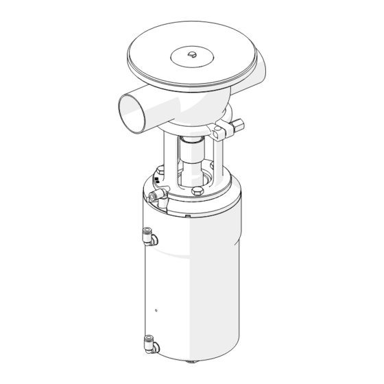
Page 26: Exploded Drawing And Parts List
Technical Specifications 9.7. EXPLODED DRAWING AND PARTS LIST INOXPA S.A.U. 10.252.30.05EN · (0) 2023/10... - Page 27 EPDM / FPM / HNBR O-ring EPDM / FPM / HNBR O-ring EPDM / FPM / HNBR lantern 1.4301 (AISI 304) screw allen bolt clamp 1.4301 (AISI 304) shaft fixation sleeve 1.4301 (AISI 304) bushing 1.4301 (AISI 304) diffuser PTFE + graphite shaft fixation core 1.4301 (AISI 304) 1) recommended spare parts INOXPA S.A.U. 10.252.30.05EN · (0) 2023/10...
- Page 28 How to contact INOXPA S.A.U.: Contact details for all countries are continaually updated on our website. Please visit www.inoxpa.com to access the information. INOXPA S.A.U. Telers, 60 - 17820 - Banyoles - Spain...
Need help?
Do you have a question about the INNOVA T and is the answer not in the manual?
Questions and answers