User Manuals: Rosslare AC-425-B Control Panel
Manuals and User Guides for Rosslare AC-425-B Control Panel. We have 3 Rosslare AC-425-B Control Panel manuals available for free PDF download: Installation And User Manual, Hardware Installation And User's Manual
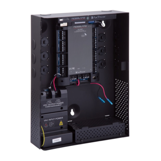
Rosslare AC-425-B Installation And User Manual (46 pages)
Expandable 4-Reader Networked
Access Control Panel
Brand: Rosslare
|
Category: Control Panel
|
Size: 1 MB
Table of Contents
Advertisement
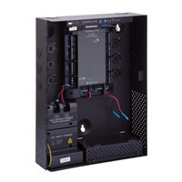
Rosslare AC-425-B Hardware Installation And User's Manual (42 pages)
Expandable 4-Reader Networked Access
Brand: Rosslare
|
Category: Control Panel
|
Size: 1 MB
Table of Contents
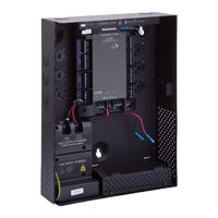
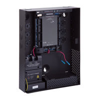
Rosslare AC-425-B Hardware Installation And User's Manual (42 pages)
Expandable 4-Reader Networked Access Control Panel
Brand: Rosslare
|
Category: Control Panel
|
Size: 1 MB
Table of Contents
Advertisement