
Related Manuals for RTS PAP-32


Summary of Contents for RTS PAP-32
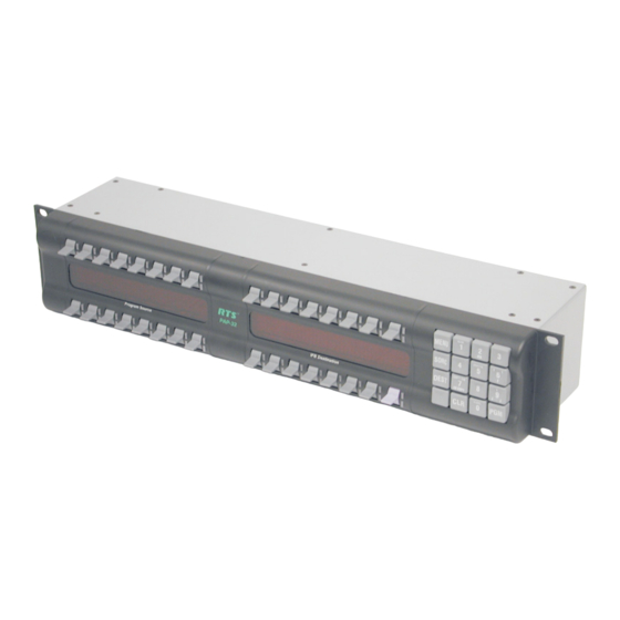
- Page 1 MODEL PAP-32 Program Assignment Panel Upto and including Version 0.0.5 9350-7704-000 Rev E 7/2006...
- Page 2 OTICE The product information and design disclosed herein were originated by and are the property of Telex Communications, Inc. Telex reserves all patent, proprietary design, manufacturing, reproduction, use and sales rights thereto, and to any article disclosed therein, except to the extent rights are expressly granted to others.
-
Page 3: Table Of Contents
Chapter 1: Introduction Introduction ...3 Features ...3 Specifications ...4 Chapter 2: Configuration and Operation Configuration ...5 Setting Address ...5 Panel Options ...5 Connections ...6 Operation ...7 Viewing the Program Source for an IFB ...7 Viewing What IFBs a Program Source Feeds ...7 Changing an IFB’s Program Source ...7 Program Source Changes Made Elsewhere ...8 Assigning Source and IFB Keys ...8... -
Page 5: Chapter 1: Introduction
This manual describes the installation, programming, and operating procedures for the RTS Model PAP-32 Program Assignment Panel. The PAP-32 provides the user with the ability to assign one of up to 16 program sources to up to 16 different IFB destinations. Through the use of standard EKP-32 expansion panels, the PAP-32 can be extended to up to 64 program sources and 64 IFB destinations. -
Page 6: Specifications
Introduction Power Supply Connection PAP-32 Rear Panel Features FIGURE 2. Specifications Matrix Connections DE-9S Female RJ12 Female Power Requirements 100-240 VAC. 50/60 Hz, 1A Environmental Operating Temperature 0° C to 50° C Storage Temperature -20° C to 75° C Humidity (Operating and Storage) -
Page 7: Chapter 2: Configuration And Operation
A16-position rotary switch is used to select the polling ID. Valid IDs are 1-15. (Note, letters A through F on the rotary switch represent IDs 10 through 15.) There can be at most one PAP, PAP-32 or LCP-102 at any given ID. Use a small flat blade screw driver to rotate the switch to the desired setting. -
Page 8: Connections
Connections The PAP-32 connects to the UIO-256/PAP port, J3 on an ADAM system, port 902 on an ADAM CS system, or port J26 on a Zeus system. The baud rate, as with all UIO-256, PAP, and LCP-102 devices, is fixed at 76.8 K baud. -
Page 9: Operation
IFB number and an output bus is controlled by editing the IFB definition table in AZedit. Suppose IFB #1 is defined to have #600 as its output bus. When changing this IFB’s program input, the PAP-32 refers to IFB #1; it does not refer to port #600. -
Page 10: Program Source Changes Made Elsewhere
Program Source Changes Made Elsewhere Whenever the program source for an IFB changes, if that IFB appears on a key on the PAP-32, the alpha for that key flashes for approximately 15 second. (If a PAP-32 changes a program source, the tally is suppressed for that PAP-32; however, any other PAP-32s connected to the intercom will see the change tally.) Press the IFB key to vie its new program input terminates... -
Page 11: Menu Functions
15 seconds, or when the Clear key is pressed. Display / Panel ID Shows the polling ID of the PAP-32 (in the range 1 through 15). Display / Setup Pages Shows the pages allocated to the PAP32 and EPAP32 panels. - Page 12 The PAP-32 saves its key assignment is non-volatile memory. When the PAP-32 powers up, in a different system than it was last connected to, it is possible for some of its key assignments to be out of range (port number or IFB number too...
- Page 13 Notes Notes...
Need help?
Do you have a question about the PAP-32 and is the answer not in the manual?
Questions and answers