Table of Contents
Advertisement
Quick Links
Advertisement
Table of Contents

Related Manuals for Ametek ta7000


Summary of Contents for Ametek ta7000
- Page 1 USER MANUAL ta7000F Gas Purity Monitor PN T900-014, Rev B...
- Page 2 AMETEK Process Instruments assumes no responsibility or liability for any errors or inaccuracies that may appear in this document. AMETEK Process Instruments is not responsible for any infringement of patents or other rights of third parties that may result from the use of this document. The content of this document is furnished for informational purposes only, is subject to change without notice, and does not represent a commitment or guaranty by AMETEK Process Instruments.
-
Page 3: Table Of Contents
Contents Safety Notes ..............................vi Grounding ..............................vi Personnel and Equipment Safety Information................vii General Safety Considerations .......................x Hydrogen (H ) Gas Flow ......................x Electrical Hazard ........................x Electromagnetic Compatibility (EMC) ....................xi Warning Labels ..........................xii OVERVIEW ..........................1-1 Introduction to the ta7000F Gas Purity Monitor .................1-1 Functional Overview of the ta7000F Gas Purity Monitor ............1-2 ta7000F Gas Purity Monitor Front Panel..................1-5 INSTALLATION AND START-UP....................2-1... - Page 4 Powering Up the ta7000F Gas Purity Monitor................2-17 Starting the ta7000F in the Warm-Up Cycle ............... 2-18 Working From the Run Mode Screen ................2-19 Initiating a Blank Run ......................2-20 USER INTERFACE ........................3-1 Introduction to the User Interface ....................3-1 Working From the User Interface ....................3-2 Operator State Diagram (Menu Map) ..................3-3 Working From the Main Menu ......................3-4 Working From the Page Screens .......................3-5...
- Page 5 Nitrogen Carrier Gas (for Oxygen and Hydrogen Models Only) ..........5-4 Chassis ................................5-4 Outputs ..............................5-4 ta7000F PLC Output Format .......................5-4 Communication Ports ...........................5-5 Parallel Printer Port (LPT1) ........................5-5 PN T900-014, Rev B Contents | v...
-
Page 6: Safety Notes
Safety Notes WARNINGS, CAUTIONS, and NOTES contained in this manual emphasize critical instructions as follows: Important information that should not be overlooked. An operating procedure which, if not strictly observed, may result in personal injury or environmental contamination. An operating procedure which, if not strictly observed, may result in damage to the equipment. -
Page 7: Personnel And Equipment Safety Information
Personnel and Equipment Safety Information This section describes important safety information to avoid personal injury and dam- age to the equipment while installing, operating, maintaining, or servicing the equip- ment. All safety regulations, standards, and procedures at the installation location must be followed. - Page 8 Operators should not attempt to repair the ta7000F. Any repairs made without first consulting AMETEK Customer Service shall void the manufacturer’s war- ranty PN T900-014, Rev B...
- Page 9 Use Proper Wiring To avoid fire hazards, use only the wiring specified in the “Installation and Start-Up” chapter of this manual. Avoid Electrical Overload To avoid electrical shock or fire hazard, do not apply a voltage to a terminal that is outside the range specified for that terminal. Ground the Product Follow the grounding instructions provided in the “Installation and Start-Up”...
-
Page 10: General Safety Considerations
General Safety Considerations The following safety items must be observed to avoid personal injury and to prevent damage to the ta7000F Monitor. All personnel involved in installation, operation or service of the ta7000F should be thoroughly familiar with these items. These consider- ations are in addition to all site specific safety procedures. -
Page 11: Electromagnetic Compatibility (Emc)
Electromagnetic Compatibility (EMC) Read and follow the recommendations in this section to avoid performance variations or damage to the internal circuits of this equipment when installed in harsh electrical environments. The various configurations of the ta7000F should not produce, or fall victim to, electromagnetic disturbances as specified in the European Union’s EMC Directive. -
Page 12: Warning Labels
Achtung – Heiße Oberfläche Environmental Information – WEEE This AMETEK product contains materials that can be reclaimed and recycled. In some cases the product may contain materials known to be hazardous to the environ- ment or human health. In order to prevent the release of harmful substances into the environment and to conserve our natural resources, AMETEK recommends that you arrange to recycle this product when it reaches its “end of life. -
Page 13: Overview
Overview This manual is intended as a guide for operation of the AMETEK ta7000F Gas Purity Monitor. This manual is not intended as a service guide and does not contain service information. The ta7000F should only be operated by person- nel who have been properly trained in the procedures required for safe opera- tion of the ta7000F. -
Page 14: Functional Overview Of The Ta7000F Gas Purity Monitor
Functional Overview of the ta7000F Gas Purity Monitor To achieve the specified performance, the ta7000F Monitor performs the pri- mary functions described below. Component Function Carrier Gas Purification A Getter Purifier is included as integral component of the car- rier gas flow path. Impurities are reduced to a level of less than 100 PPT. - Page 15 Front Panel Main Processor Display Module Flow Control Module Electrometer Chassis Control Module Detector Controller Chromatograph Module Detector Power Supply Power Supply FID Module Gas Blender Stream Selector Carrier/Sample Regulator Rear Panel Figure 1-1. Internal general component layout. Overview PN T900-014, Rev B...
- Page 16 Component Function Operating System The six (6) button keypad allows you to enter commands to the microprocessor, which monitors detector operation, controls heated zones, and operates all internal valve functions. External signal outputs for a data collection system or host computer are located at the ta7000F Rear Panel.
-
Page 17: Ta7000F Gas Purity Monitor Front Panel
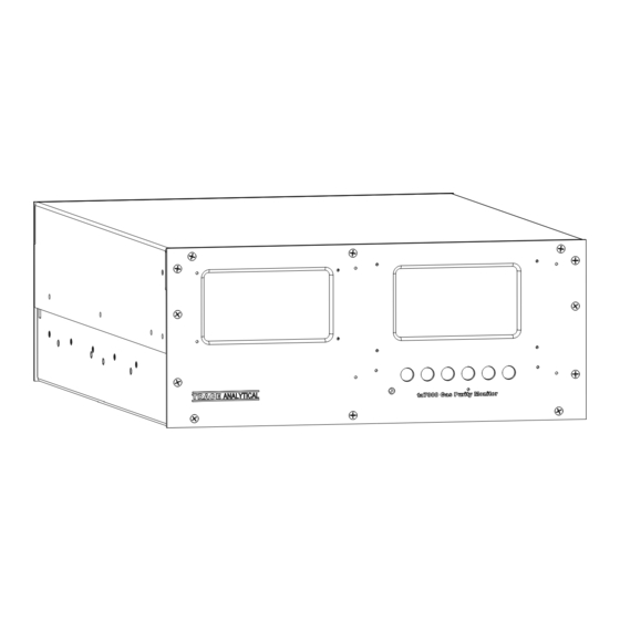
ta7000F Gas Purity Monitor Front Panel Component Function Front Panel and User The User Interface is located on the front panel. The User Inter- Interface face is made up of a Display screen and Menu keys. See “Intro- duction to the User Interface” in Chapter 3 for more information. Figure 1-2. - Page 18 Component Function Display Screen and The Display screen displays all current information and options. Menu Keys • The Status Bar displays the current status of the ta7000F Moni- tor. This area also displays the active screen name, the system time and date, and other important Status information. •...
-
Page 19: Installation And Start-Up
Installation and Start-up Safety Considerations To ensure a smooth installation of the AMETEK ta7000F Gas Purity Monitor and to get the maximum performance, several aspects should be considered. This guide discusses the important points for a successful installation. Before beginning the installation of the ta7000F and before powering it up, review and follow all safety information following the Table of Contents near the beginning of this manual. - Page 20 Carrier Gas Purifiers External gas purifiers must be completely conditioned with gas flow- ing through them before connection to the ta7000F. Failure to prop- erly condition purifiers can result in serious contamination. Flame Ionization Detector (FID) Flame Ignition Do not ignite the FID flame unless the FID is at operation temperature. Doing so will cause moisture to condense in the unheated FID and will short out the electrometer input leads.
-
Page 21: Pre-Installation Requirements
Failure to comply with these storage conditions will void your warranty. Unpacking and Inspecting the Equipment Remove any packing material from the ta7000F Monitor. Check for damage. If equipment is damaged, notify the carrier and contact AMETEK Service (https:// www.AMETEKpi.com/customersupport/requestsupport) immediately if parts are missing or damage is found, and to verify if damaged parts will require replacement prior to safely installing and operating the equipment. -
Page 22: Ta7000F Monitor Location Requirements
Be within the ambient temperature limits listed in the specifications. If the ambient temperature is outside the specified limits or the vibration is excessive, contact your AMETEK representative to discuss solutions and special options to address ambient temperatures. Be clean with minimum particulate matter and dust in the air. -
Page 23: Electrical Preparations And Connections
• AMETEK recommends connecting the ta7000F and low powered accesso- ries to a dedicated electrical circuit. Do not plug the ta7000F into a circuit that is shared with other equipment with large intermittent current loads. -
Page 24: Support Gas Utilities Preparations
Support Gas Utilities Preparations The ta7000F needs several support gases to ensure proper operation. Refer to the Specifications chapter for detailed gas specifications for purchasing gases in cylinders. To achieve the low detection limits, it may be essential to further clean the gases with external purifiers. -
Page 25: Tools, Equipment, Hardware, And Supplies Required For Installation
Adapter, 1/16-inch VICI to 1/4-inch VCR: Seven (7) each required for gas connections via 1/16-inch tubing umbilical at regulators, FID Air inlet and FID H2 inlet. AMETEK PN 220–091. Nut, 1/4-inch VCR Gland, male: Seven (7) each required for use with VICI-VCR adapters at regulators, FID Air inlet, and FID H2 inlet. -
Page 26: Installing The Mechanical Components
If any inconsistencies are encountered during installation, stop im- mediately. Do not continue the installation without direction from AMETEK Customer Service. The ta7000F performance level depends upon the care and atten- tion to proper handling procedures while making gas connections. - Page 27 Front Panel Main Processor Display Module Flow Control Module Electrometer Chassis Control Module Detector Controller Chromatograph Module Detector Power Supply Power Supply FID Module Gas Blender Stream Selector Carrier/Sample Regulator Rear Panel Figure 2-1. Internal general component layout. Installation and Start-Up PN T900-014, Rev B...
- Page 28 4.010 0.50 5.90 0.520 SIDE VIEW REVISIONS ON CONTAINED IN THIS DRAWING IS THE SOLE PROPERTY OF CAL ANY REPRODUCTION IN PART OR WHOLE WITHOUT REV. DESCRIPTION ERMISSION OF TRACE ANALYTICAL IS PROHIBITED. 26.125 UNLESS OTHERWISE SPECIFIED DIMENSIONS ARE IN INCHES APPROVALS DRAWN Iverson...
-
Page 29: Making Gas Connections
Making Gas Connections To prepare for the gas connections: • Remove any 1/16-inch or 1/8-inch VICI plugs and 1/4-inch VCR caps from the ta7000F Rear Panel. • Remove all other shipping caps immediately prior to connection of gas sup- plies. •... -
Page 30: Connecting And Purging The Carrier Gas Getter Purifier (If It Is Not Installed)
Connecting and Purging the Carrier Gas Getter Purifier (if it is Not Installed) This procedure is required if the Getter Purifier has not already been installed. Before beginning the installation of the Getter Purifier, gather the purifier, nec- essary tools, and consumables and have them at hand near the ta7000F Rear Panel. -
Page 31: Connecting Actuator Gas
9. Partially loosen the 1/4-inch female VCR cap at the outlet of the purifier to allow a modest gas flow that will purge the purifier. 10. Allow gas to flow 2–3 minutes for adequate purging. 11. Remove the 1/4-inch female VCR cap on the outlet of the purifier. 12. -
Page 32: Connecting Fid Hydrogen
Connecting FID Hydrogen Hydrogen quality can also dramatically affect instrument performance. See gas specifications under “FID Hydrogen” in Chapter 5 for details. The instrument connection is made at the “FID H2” 1/16-inch VICI port on the ta7000F Rear Panel. Pressurize this external line to 50 PSIG (minimum 50 PSIG, maximum 60 PSIG). -
Page 33: Making The Electrical Connections
Making the Electrical Connections Connecting AC Power Before making the AC power connections, verify that the operat- ing voltage of the instrument matches the available AC power. The ta7000F does not auto-select for varying power line voltages. The instrument operating voltage is labeled on the ta7000F Rear Panel directly above the AC Power Connector/Power Switch. -
Page 34: Connecting To A Printer
The Printer Port follows standard parallel printer protocols. The ta7000F is compatible with Hewlett Packard printers, model numbers HP-6xx, HP-7xx , and HP-8xx. AMETEK recommends using one of these suggested models. DB 25 Male 14 15 16 17 18 19 20 21 22 23 24 25 1 2 3 4 5 6 7 8 9 10 11 12 13 Figure 2-5. -
Page 35: Powering Up The Ta7000F Gas Purity Monitor
On (GREEN) and the rear cooling fan should begin operating. The initial start-up screen should appear within a few seconds. If any of these does not occur, turn the power Off immediately and contact AMETEK Customer Service or your local authorized service agent. -
Page 36: Starting The Ta7000F In The Warm-Up Cycle
Starting the ta7000F in the Warm-Up Cycle The Initial start-up screen (see Figure 2-6) will display two menu items: Warmup and Page. Press Page to view the first of three (3) system setup pages. Refer to “Working From the Page Screens, ” later in this chapter. Press the Warmup key to initiate the instrument’s Warm-Up Cycle. -
Page 37: Working From The Run Mode Screen
Working From the Run Mode Screen After the ta7000F has warmed up to normal operating temperature, press the Run key to view the Main Menu screen. The upper-left corner of the screen will display “Idle Mode” to indicate the ta7000F is not measuring or perform- ing any other actions. -
Page 38: Initiating A Blank Run
To stop the instrument press the Idle key and a Pound character ( ‘ # ‘ ) will ap- pear next to Run Mode in the Status Bar. This asterisk indicates that the instru- ment will stop running at the end of the next cycle. To continue running the instrument after the Idle key has been pressed, simply press the Idle key again and the Pound character ( ‘... -
Page 39: User Interface
Monitor's User Interface. Introduction to the User Interface The AMETEK ta7000F Gas Purity Monitor User Interface – which consists of a Display screen and Menu Keys – is located on the ta7000F front panel. The screen displays information and options used to operate the ta7000F. The Menu Keys correspond with Menu Labels (names) on the Display screens and are used for all input to the operating system. -
Page 40: Working From The User Interface
Working From the User Interface While working from the User Interface, the following rules apply: • From the Main Window screen, navigate through the various screens (Menu items) by pressing the corresponding Menu keys to select a Main Menu option. •... -
Page 41: Operator State Diagram (Menu Map)
Operator State Diagram (Menu Map) Operator State Diagram Power-up Warmup Warmup Edit Edit System Temperatures Page Warm-up Page Page Settings and Status Cool Page Return to Source Calibration Idle Settings Page Edit Figure 3-2. Blank Calib Operator State Diagram (Menu Map). The State Diagram illustrates how the menus are arranged. -
Page 42: Working From The Main Menu
Working From the Main Menu After warm-up has completed successfully the Main Menu screen will be displayed. The Main Menu is a set of primary choices leading to other menu options. 12:39:30 Idle Mode NHMC = Page Cool Calib Blank Figure 3-3. -
Page 43: Working From The Page Screens
Working From the Page Screens From the Main Menu, press the Page key to view the System Settings screen (Figure 3-4). Press Page again to view the Temperatures & Status screen, and again to the view the Calibration Settings page. Pages that allow changes ‘... -
Page 44: Working From The System Settings Screen
Working From the System Settings Screen The first Page screen (System Settings screen, Figure 3-4) is for general con- figuration settings. Setting the Clock This screen allows you to set the ta7000F Time and Date. Use the Up/Down arrow keys to select Clock, then press the Edit key. Move the cursor ( ‘ ‘... -
Page 45: Viewing System Information On The Temperatures & Status Screen
Viewing System Information on the Temperatures & Status Screen From the System Settings screen press the Page key to view the Tempera- tures & Status screen, which displays status information about the critical heated zones and status of the Detector, and the Carrier and Calibration gas pressures. -
Page 46: Working From The Calibration Screen
Working From the Calibration Screen From the Temperatures & Status screen press the Page key to view the Cali- bration screen (Figure 3-6), which displays information about the most recent calibration run. From this screen you can also configure Auto-Calibration param- eters. -
Page 47: Setting Auto-Calibration Parameters
Setting Auto-Calibration Parameters The Calibration screen (Figure 3-6) is also used to set up automatic calibra- tions. The ta7000F Monitor does not need Zero calibration. An external Calibra- tion gas source must be connected to the AUX port on the ta7000F Rear Panel of the ta7000F marked. -
Page 48: Initiating A Manual Calibration
Initiating a Manual Calibration From the Main Menu, press the Calib key to start a Manual calibration run of the ta7000F. The ta7000F does not need Zero calibration. An external Calibra- tion gas source must be connected to the AUX port on the ta7000F Rear Panel. Refer to the Specifications chapter for Calibration gas specifications. -
Page 49: Saving Changes To Non-Volatile Ram
Saving Changes to Non-Volatile RAM After changes have been made by Manual calibration or on any of the Page screens, the system LED will turn RED. This indicates that there is a system error or system state change. The ta7000F must be in Idle or Warm-up mode before it will accept or save changes into non-volatile RAM. -
Page 50: Powering Down The Ta7000F Gas Purity Monitor
Powering Down the ta7000F Gas Purity Monitor Powering down the ta7000F Monitor for maintenance or for any other reason is very simple. Carrier gas to the ta7000F must not be powered down until all tem- peratures are below 50 °C. If the ta7000F Monitor must be powered down due to an emergency or for any safety reason, simply switch the ta7000F AC Power Switch –... -
Page 51: Troubleshooting
Error Condition / Description / Corrective Action Chassis Controller Error Internal electronics failure. Corrective Action: Contact AMETEK Service or qualified service representative for troubleshooting assistance. Detector Controller Error Internal electronics failure. Corrective Action: Contact AMETEK Service or qualified service representative for troubleshooting assistance. -
Page 52: Temperature Out Of Range
Analog Signal Zeroing Error The instrument has failed to Zero the detectors analog signal. Corrective Action: Contact AMETEK Service or qualified service representative for troubleshooting assistance. Calib Pressure Out of Range Calibration gas pressure is not within normal operating range. -
Page 53: Event Program Error
Internal event program has not been correctly entered, is missing, or has been corrupted. Corrective Action: Contact AMETEK Service or qualified service representative for troubleshooting assistance. Printer Error Printer is not connected, is turned Off, or is not functioning properly. - Page 54 This page intentionally left blank. 4-4 | ta7000F Gas Purity Monitor PN T900-014, Rev B...
-
Page 55: Specifications
Specifications Model Designation and Detection Limit Specifications ta7000F Standard Model Lower Detection Limit Non-Methane Carbon Methane (CH Hydrocarbons Monoxide (CO) Sample Gas Model (NMHC) PPB Nitrogen (N ta7000F-N2 <0.5 <1.0 <2.0 Argon (Ar) ta7000F-Ar <0.5 <1.0 <2.0 Helium (He) ta7000F-He <0.5 <1.0 <2.0... -
Page 56: Performance Specifications
Performance Specifications Specification Description Accuracy, EDL Mode Greater of ±0.25 PPB CH ; ±0.5 PPB CO ; ±1.0 PPB NMHC; (Enhanced Detection ±10 % of reading Limit Mode) Range 0–199.9 PPB Response Time 10 minutes to 99 % response 60 minutes to 75 % response in EDL Mode. Response time is independent of sample concentration. -
Page 57: Actuator Gas
Actuator Gas Specification Description Inlet Fitting 1/8-inch VICI compression fitting Inlet Pressure Range 4.8–10.2 BAR (70–150 PSIG) Gas Type Inerts (Nitrogen, Argon, Helium), 7 nines or better or CDA, dewpoint < -65 °C Gas Type Inerts (Nitrogen, Argon, Helium), 7 nines or better (for ta7000F-O only) Calibration Gas... - Page 58 Nitrogen Carrier Gas (for Oxygen and Hydrogen Models Only) Specification Description Inlet Fitting 1/4-inch male face seal fitting* Inlet pressure range 4.8–6.1 BAR (70–90 PSIG) Inlet pressure stability +2 %, UHP regulator required Flow rate 300 cc/minute Purity 99.9999 % (<1 PPM total impurity CO between calibration) * 1/4-inch face seal x 1/16-inch adapter fittings are available from ΑΜΕΤΕΚ.
- Page 59 Field 1 Date & Time of RUN Field 2 Analyzer Serial # Field 3 Run/Maintenance Field 4 EDL/Single Analysis Field 5 Field 6 ta7000F Error Status Field 7 Impurity Name Field 8 Concentration in PPB x 100 Each field is defined as: DDDD-DD-DD TT:TT:TT,#,R,S,A,EEEEEEEE,NNNNN,C, …...
- Page 60 This page intentionally left blank. 5-6 | ta7000F Gas Purity Monitor PN T900-014, Rev B...
- Page 61 AMETEK Process Instruments delivers worldwide sales and service support through a network of direct and factory-trained global distribution channels. AMETEK Service Assistance Program plans offer coverage up to 24 hours a day, 365 days of the year. As worldwide experts in the manufacture of process analyzers and instrumentation, we have supplied solutions to industry since 1962, providing the widest range of analysis technology available.
Need help?
Do you have a question about the ta7000 and is the answer not in the manual?
Questions and answers