
Related Manuals for Ametek Thermox WDG-V UOP


Summary of Contents for Ametek Thermox WDG-V UOP
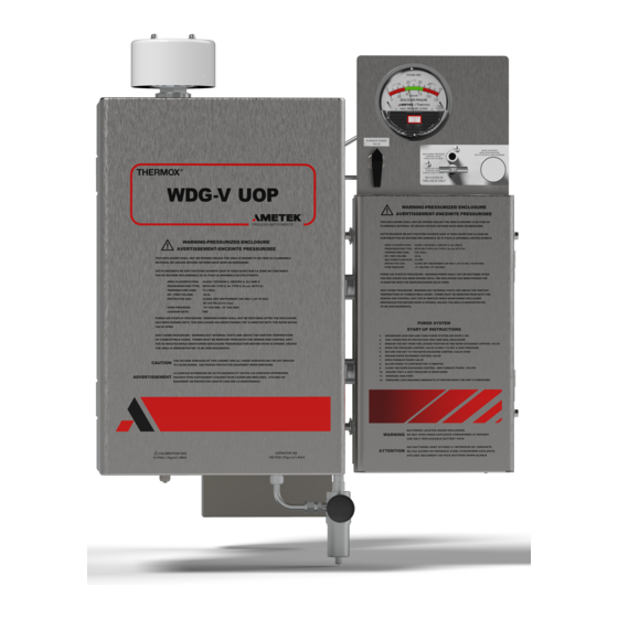
- Page 1 Thermox IECEx/ATEX ® WDG-V UOP Combustion Analyzer User Manual Thermox 150 Freeport Road Pittsburgh, PA 15238 PN 9000-280-VE Rev. B...
-
Page 2: Offices
© 2019 AMETEK This manual is a guide for the use of the Thermox WDG-V UOP. Data herein has been verified and validated and is believed adequate for the intended use of this instrument. If the instrument or procedures are used for purposes over and above the capabilities specified herein, confirma- tion of their validity and suitability should be obtained;... -
Page 3: Table Of Contents
Contents Offices ..........................ii Safety Notes ........................ vii Electrical Safety ......................vii Grounding ........................vii Special Conditions for Safe Use ................viii HAZARDOUS LOCATION LIMITATIONS ...........viii Warning Labels ......................ix Environmental Information (WEEE) ............... ix General Safety Summary .................... x Use Proper Wiring ....................x Avoid Electrical Overload .................. - Page 4 Transient and RFI interference ..............3-19 Current Output Connections ................. 3-20 Standard current outputs ................3-20 Alarm Contact Connections................3-21 Standard alarm connections .................3-21 Remote Calibration Unit Connections ............3-23 Digital Input to Initiate Remote Calibration Unit ........3-23 iv | Thermox WDG-V UOP IECEx/ATEX...
- Page 5 Standard Connection using PC Configurator Software ........3-25 Overview ......................3-25 Connecting to the WDG-V UOP ..............3-25 Setting the Address using the Dip Switch ...........3-25 Connecting the PC to the Analyzer ..............3-26 Chapter 4 AMEVision Display Installation Guide ............4-1 The AMEVision Display Unit ................
- Page 6 Electronics Replacement ..................6-13 Recommended Maintenance Schedule ............... 6-14 Calibration ......................6-14 Replacement Parts List ................... 6-15 Sensor ......................... 6-15 Remote Calibration Unit (RCU) ..............6-15 vi | Thermox WDG-V UOP IECEx/ATEX...
-
Page 7: Safety Notes
Safety Notes WARNINGS, CAUTIONS, and NOTES contained in this manual emphasize critical instructions as follows: An operating procedure which, if not strictly observed, may result in personal injury or environmental contamination. An operating procedure which, if not strictly observed, may result in dam- age to the equipment. -
Page 8: Special Conditions For Safe Use
Voltages are 104-127 VAC or 207-253 VAC, 740 VA. Make sure the location in which the WDG is installed meets all of the Hazardous Location Limitation criteria for a Category 3 analyzer de- scribed above. viii | Thermox WDG-V UOP IECEx/ATEX... -
Page 9: Warning Labels
Achtung - Heiße Oberfläche Environmental Information (WEEE) This AMETEK product contains materials that can be reclaimed and recycled. In some cases the product may contain materials known to be hazardous to the environment or human health. In order to prevent the release of harmful... -
Page 10: General Safety Summary
To avoid electric shock or fire hazard, do not operate this product with covers or panels removed. Use Proper Fuse To avoid fire hazard, use only the fuse type and rating specified for this prod- uct. x | Thermox WDG-V UOP IECEx/ATEX... -
Page 11: Product Damage Precautions
Product Damage Precautions Use Proper Power Source Do not operate this product from a power source that applies more than the voltage specified. Do Not Operate with Suspected Failures If you suspect there is damage to this product, have it inspected by qualified service personnel. - Page 12 TO ANY OTHER MANUFACTURER’S EQUIPMENT, WHETHER SOLD SEPARATELY OR IN CONJUNC- TION WITH EQUIPMENT OF OUR MANUFACTURE. WE DO NOT AUTHORIZE ANY REPRESENTATIVE OR OTHER PERSON TO ASSUME FOR US ANY LIABILITY IN CONNECTION WITH EQUIPMENT, OR ANY PART THEREOF, COVERED BY THIS WARRANTY. xii | Thermox WDG-V UOP IECEx/ATEX...
-
Page 13: Chapter 1 System Overview
SYSTEM OVERVIEW UOP CCR Platforming Process “The CCR Platforming process uses naphtha boiling in the range of 180-400°F to produce high-octane gasoline or petrochemical precursors. This technology is the world’s leading reforming process. It is also the technology of choice for new reforming applications, providing refiners with proven, ultra-low-pressure (50 psig reactor pressure) operation and producing the highest reforming yields. - Page 14 UOP-type system. The oxygen analyzer is critical to the UOP- patented CCR process and designed specifically to monitor oxygen levels during catalyst regeneration. 1-2 | Thermox WDG-V UOP IECEx/ATEX...
-
Page 15: Thermox And Wdg Uop Series
Thermox and WDG UOP Series 1980 Thermox, in conjunction with the UOP Process Division, de- veloped the WDG-III UOP to monitor the gaseous atmosphere during a regeneration cycle of UOP’s Licensed Continuous Catalyst Regeneration process. With their technical guidance this analyzer evolved to the current model WDG-IV UOP/RP . 1999 UOP and Thermox addressed plugging and corrosion issues with the external sample return line which is outside the scope... -
Page 16: Analyzer Operations
(up to 500°F, 260°C inside the cover). Allow sensor components to cool for at least 90 minutes before work- ing inside the sensor. Use caution and wear appropriate gloves when handling components or when touching the sensor cover! 1-4 | Thermox WDG-V UOP IECEx/ATEX... -
Page 17: Basic Elements Of The Analyzer
All required I/O comes with the analyzer. See the “Electronics” section for descriptions. Analyzer Communications The analyzer is configured, calibrated and monitored using the MODBUS RTU interface. AMETEK/Thermox provides two options for communicat- ing with the analyzer: • AMEVision Display User Interface •... -
Page 18: How The Oxygen Measuring Cell Works
A refer- ence gas, usually air (20.9% O ), is used for one of the gases. Figure 1-1. Zirconium oxide cell principle of operation. 1-6 | Thermox WDG-V UOP IECEx/ATEX... -
Page 19: Measuring Non-Combustible Gases
The voltage of the cell depends on temperature, and so the cell is main- tained at a constant temperature. The oxygen content is then determined from the Nernst equation: where R and F are constants, T is absolute temperature, and O and O the oxygen partial pressures on either side of the cell. -
Page 20: Sensor Operations - Wdg-V Uop
A portion of this gas passes over the zirco- nia sensor. Because the aspirator gas contains no oxygen, the sample can simply be returned to the process. Figure 1-2. Typical WDG-V UOP sensor configuration. 1-8 | Thermox WDG-V UOP IECEx/ATEX... -
Page 21: Rtd Flow Sensor
RTD Flow Sensor Figure 1-3a. Sensor Enclosure detail. Figure 1-3b. Flow sensor location. The RTD flow sensor monitors the sample flow through the fast loop as the temperature of the gas flowing past it. well as An alarm is generated when the temperature reaches 100°C lower than the temperature set during normal operation. -
Page 22: Temperature Zones And Heaters
Limit) in the process. The flame arrestors are not, however, intended to protect the process when the combustibles’ levels are constantly high. Two additional flame arrestors are provided with the unit for the cal gas inlet and the vent. 1-10 | Thermox WDG-V UOP IECEx/ATEX... -
Page 23: Electronics
Electronics • Connections to the analyzer are made through the wiring card. The wiring card is located on the right side in a separate section of the analyzer. • Analyzer wiring and customer wiring (power, I/O) are directly con- nected to the main electronics. •... -
Page 24: Standard Alarm Connections
This alarm differs from the service alarm in that there is not necessarily a problem with the analyzer when this alarm is active. The relay contacts are normally-open and are OPEN (de-energized) when the concentration readings are not valid. 1-12 | Thermox WDG-V UOP IECEx/ATEX... -
Page 25: Remote Calibration Unit Connections
Remote Calibration Unit Connections Oxygen-Only Remote Calibration Unit Connections Oxygen-Only Remote Calibration Unit (RCU) connections on the WDG-V wiring card, and their RCU connections, are as follows: ZERO GAS - WDG-V Terminal Z to Pin 13 on RCU ASPIRATOR - WDG-V Terminal A to Pin 14 on RCU SPAN - WDG-V Terminal S1 to Pin 15 on RCU VALVE COMMON - WDG-V Terminal ‘V’... -
Page 26: Digital Input To Initiate Remote Calibration Unit
The switch you connect to this digital input must be a normally open switch. Digital input connections are labeled as follows on the wiring card: • Terminal Block Connections Figure 1-5. Right side cut-away view showing terminal block locations. 1-14 | Thermox WDG-V UOP IECEx/ATEX... - Page 27 Figure 1-6. Terminal Block Detail (customer connections located in the center section). System Overview 1-15...
-
Page 28: Technical Support
Technical Support AMETEK/Thermox is committed to providing the best technical support in the industry. If you need service or application assistance, please call AMETEK/Thermox at (412) 828-9040, or your local AMETEK/Thermox representative. Before you call the factory for technical support, run test gases and record... -
Page 29: Chapter 2 Specifications
SPECIFICATIONS Sensor : WDG-V UOP Output Range From 0-1% to 0-100% Accuracy ± 0.75% of measured value or ± 0.05% oxygen, whichever is greater Response 90% of a process step change < 30 secs. < 0.1% of cell output per month (< 0.005% O per month with 2% O Drift applied) -
Page 30: Approvals And Certifications For Wdg-V Uop
(IECEx ETL 19.0039X) ATEX 2014/34/EU EN 60079-0: 2018 EN 60079-2: 2014 (ITS19ATEX14526X) General Safety 2014/35/EU EN 61010-1: 2010 Edition 3.0 US/CAN UL/CSA 61010-1: 2010 Edition 3.0 (cETLus) EMC 2014/30/EU EN 61326-1: 2013 Edition 2.0 2-2 | Thermox WDG-V UOP IECEx/ATEX... -
Page 31: Remote Calibration Unit (Rcu)
Remote Calibration Unit (RCU) Enclosure UL Type 4X (NEMA 4X (IP66), Div II Environment Ambient Temperature: -18°C to 60°C Humidity: 0 to 90%, non-condensing Max Altitude: 2000 Meters IEC Installation Category II IEC Pollution Degree 2 System Compliance EMC Compliance: 2004/108/EC Safety Compliance: 73/23/EEC Specifications | 2-3... -
Page 32: Wdg-V Uop Series Analyzer Rating Labels
£ £ Intertek Ex pzc IIC T3 Gc IECEx ETL 19.0039X ITS19ATEX14526X PROCESS & ANALYTICAL INSTRUMENTS DIVISION 150 Freeport Rd., Pittsburgh, Pa. 15238 ENCLOSURE TYPE IP65 Label P/N: 7001-976-KE Product Labeling for Hazardous Locations 2-4 | Thermox WDG-V UOP IECEx/ATEX... -
Page 33: Wdg-V Uop Series Analyzer Markings
WDG-V UOP Series Analyzer Markings WARNING-PRESSURIZED ENCLOSURE AVERTISSEMENT-ENCEINTE PRESSURISEE THIS ENCLOSURE SHALL NOT BE OPENED UNLESS THE AREA IS KNOWN TO BE FREE OF FLAMMABLE MATERIAL OR UNLESS DEVICES WITHIN HAVE BEEN DE-ENERGIZED. CETTE ENCEINTE NE DOIT PAS ÊTRE OUVERTE SAUF SI VOUS SAVEZ QUE LA ZONE NE CONTIENT PAS DE MATÉRIEL INFLAMMABLE OU SI TOUS LES APPAREILS ONT ÉTÉ... - Page 34 This page intentionally left blank. 2-6 | Thermox WDG-V UOP IECEx/ATEX...
-
Page 35: Chapter 3 Installation Guide
INSTALLATION GUIDE The operations in this chapter should be performed only by qualified service personnel experienced in electrical safety techniques. Never service the sensor unless power has been removed from the sensor, and the sensor has been allowed to cool for at least one hour. Also, always use gloves when working on the sensor. -
Page 36: Analyzer Location
Department at (412) 828-9040. We have special options to address ambient temperatures outside the listed specifications. Inspect Shipping Contents Remove any packing material from the WDG-V UOP sensor. Check for damage. If any is found, notify the shipper. 3-2 | Thermox WDG-V UOP IECEx/ATEX... -
Page 37: Mechanical Installation
Mechanical Installation • Sample Inlet Probe Installation • Exhaust Tube Installation (optional) • Sensor Mounting • Remote Calibration Unit Mounting and Plumbing (optional) Sample Inlet Probe Installation For some applications, you must first connect the sample inlet probe to the sensor before mounting the sensor. The same applies if you are installing the probe heater or exhaust tube. -
Page 38: Standard 1/4" Npt Probe Installation
Connector 1/2"T x 3/8NPT(M) Mounting Flange Assembly Gasket 3"-300# Backplate part of Sensor Long Venturi Hook Inlet Tube with RTD Flow Sensor TOP VIEW Figure 3-1a. WDG-V UOP Probe Installation. Figure 3-1b. Rear of Sensor. 3-4 | Thermox WDG-V UOP IECEx/ATEX... -
Page 39: Exhaust Tube Installation
Exhaust Tube Installation When installing the exhaust tube, connect it to the sensor before mounting the sensor to the process. The hastelloy exhaust tube allows you to extend the aspirator exhaust. The exhaust tube has a thread on only one end of the tube. To install the exhaust tube, thread it into the exhaust port on the rear of the sensor as shown in Figure 3-2. - Page 40 Figure 3-2. Sensor Mounting. A 7/16" wrench is required to open both doors to the sensor. 3-6 | Thermox WDG-V UOP IECEx/ATEX...
-
Page 41: Calibration/Aspirator Air
Calibration/Aspirator Air Required Calibration Gases and Tubing See Specifications for information on calibration gases. The span gas is the high gas; the zero gas the low gas. The span gas must be 10 times greater than the zero gas. For example, if the zero gas is 1% O , the span gas must be 10% O or higher. -
Page 42: Rapid Exchange Purge System
Practice locking and unlocking key in the RECV valve stem. Become familiar with this process to ease operation of the system. Operators must follow-step-by-step sequence in the Start-Up instruc- tions found on the electronics box lid. 3-8 | Thermox WDG-V UOP IECEx/ATEX... - Page 43 Figure 3-3a. UOP Rapid Exchange Purge System (Front). Figure 3-3b. UOP Rapid Exchange Purge System (Rear). Installation Guide | 3-9...
-
Page 44: Purging Instructions
Wait for the Enclosure Pressure Gauge to return to a “Safe” pressure and energize the protected enclosure(s) power using the local discon- nect switch. 10. Ensure the Enclosure Pressure Indicator maintains a “Safe” pressure before leaving the system unattended. 3-10 | Thermox WDG-V UOP IECEx/ATEX... -
Page 45: Aspirator And Manual Calibration Connections
Aspirator and Manual Calibration Connections The UOP processes run at either atmospheric pressure, 35 psi or 110 psi. Aspirator, calibration, and reference gas pressures must be set relative to the process pressure. Reference gas pressure is required for High Pressure (110 psi) only. Aspirator N Connections During process start-up and whenever power is removed from the... -
Page 46: Standard Rcu Mechanical Installation
RCU is -20° to 70°C. Mount the RCU as close to the sensor as possible. Shorter calibration plumbing improves response times, reduces calibration gas expense, and reduces the chance of contaminants in the calibration gas plumbing. Figure 3-4. RCU Mounting Dimensions. 3-12 | Thermox WDG-V UOP IECEx/ATEX... - Page 47 Connect the O span gas, if other than instrument air, to the alternate span gas inlet. Connect the O zero calibration gas to the O zero gas inlet connection on the RCU. Connect the combustibles span calibration gas to the combustibles span gas inlet on the RCU.
-
Page 48: Amevision Display User Interface Mounting
Connections to the sensor unit are made through the wiring card. The wiring card is located on the front-bottom of the sensor unit. Any screw terminals on the wiring card not described in this section are reserved for future use. 3-14 | Thermox WDG-V UOP IECEx/ATEX... -
Page 49: General Wiring And Conduit Requirements
General Wiring and Conduit Requirements This section provides mandatory EMC grounding, shielding, and noise protection requirements. • Sensor wiring conductors must be rated at a minimum of 80°C. All other wiring conductor ratings should be for the minimum temperature required for the equipment being connected to the analyzer, but not less than 60°C. -
Page 50: Wdg-V Uop Mains Supply Connections
AC input terminal (L or N) the AC Line or Neutral is connected to, or, if there is a Neutral used at all (i.e., 208 VAC US power connection). 3-16 | Thermox WDG-V UOP IECEx/ATEX... -
Page 51: Emc Grounding, Shielding And Noise Protection
EMC Grounding, Shielding and Noise Protection For EMC purposes, under no circumstances should you leave cable shields disconnected at one end or both ends of the cable (sensor or control unit or other device). You must use twisted-pair cable in rigid metal conduit or use twisted pair cable with an overall braided shield. - Page 52 Cable Shield(s) Conduit Housing Max. Length 1 inch Capacitor Conduit Nut GROUND STUD METHOD Cable Shield(s) Conduit Housing Max. Length 2 inches Capacitor Conduit Nut Washer Ring Terminal Figure 3-8. Direct shield grounding methods 3-18 | Thermox WDG-V UOP IECEx/ATEX...
-
Page 53: Transient And Rfi Interference
Transient and RFI interference This section describes transient and RFI interference precautions: • Although there are transient and noise protectors on all sensor unit I/O connections (communications, current outputs, sensor, etc.), this protection is intended to act as a last line of defense against unwanted transient and RFI interference. -
Page 54: Current Output Connections
3.8 mA Reading Under Range (Example: user sets range to 2-10%. Current reading is 1.9%) 4 to 20 mA Normal Operation 20.5 mA Reading Over Range (Example: range is 0-10%. Current reading is 12%) 3-20 | Thermox WDG-V UOP IECEx/ATEX... -
Page 55: Alarm Contact Connections
Alarm Contact Connections This section describes how to make wiring connections for any alarm devices you wish to connect to the control unit. Standard alarm connections The WDG-V UOP sensor provides five sets of normally open alarm contacts as follows: Terminal Block ID Description Service Alarm... - Page 56 Figure 3-9. Wiring. 3-22 | Thermox WDG-V UOP IECEx/ATEX...
-
Page 57: Remote Calibration Unit Connections
Remote Calibration Unit Connections Oxygen-Only Remote Calibration Unit Connections Oxygen-Only Remote Calibration Unit (RCU) connections on the WDG-V UOP wiring card, and their RCU connections, are as follows: ZERO GAS - WDG-V UOP Terminal Z to Pin 13 on RCU ASPIRATOR - WDG-V UOP Terminal A to Pin 14 on RCU SPAN - WDG-V UOP Terminal S1 to Pin 15 on RCU VALVE COMMON - WDG-V UOP Terminal ‘V’... - Page 58 Enclosure Maximum Overpressure The user should limit the pressure as specified by the manufacturer. 3-24 | Thermox WDG-V UOP IECEx/ATEX...
-
Page 59: Standard Connection Using Pc Configurator Software
Standard Connection using PC Configurator Software If you are connecting the analyzer using the AMEVision Display User Interface, skip this section and continue with the AMEVision Display Installation Guide following this section. Overview The WDG-V UOP PC Configurator Software comes standard with the analyzer and is used to configure, calibrate and monitor a single analyzer. -
Page 60: Connecting The Pc To The Analyzer
Instructions on using the PC software to configure and calibrate the analyzer, as well as analyzer status readings, are found in Addendum A of this manual. 3-26 | Thermox WDG-V UOP IECEx/ATEX... -
Page 61: Chapter 4 Amevision Display Installation Guide
AMEVISION DISPLAY INSTALLATION GUIDE If you are not using the AMEVision Display User Interface, skip this section, follow the PC Configurator software connection instructions in Chapter 3. The AMEVision Display Unit Figure 4-1. Standard AMEVision Display User Interface. The AMEVision Display User Interface is an intuitive remote, graphical user interface and communications link that provides easy configuration, calibration and monitoring for up to eight WDG-V UOP analyzers using a single analyzer. -
Page 62: Setting The Analyzer Address
Figure 4-2. Dip switch settings on user interface PCB. NOTE: ORIENTATION OF SWITCH MOUNTED IN ANALYZER IS UPSIDE DOWN. Close up of dip switch to set address. 321 Switch Address 1 = ON (UP) 0 = OFF (DOWN) 4-2 | Thermox WDG-V UOP IECEx/ATEX... -
Page 63: Connecting The Analyzers
Connecting the Analyzers Single Analyzer Connection When only one analyzer is connected, set the address to “1”. Multiple Analyzer Connections Up to eight (8) analyzers can be connected to a single AMEVision Display User Interface. The WDG-V UOP analyzer has extra terminal connections for daisy-chain connections. -
Page 64: Final Daisy Chain Connection Configuration Setting
Broken connection Intermittent Communications: • Poor wiring (i.e., lack of shielded twisted pair) • Termination enabled on more than one unit (on multi-unit systems) • Termination not enabled (on multi-unit systems) • Maximum distance exceeded 4-4 | Thermox WDG-V UOP IECEx/ATEX... -
Page 65: Customer I/O Connections
Customer I/O Connections AMEVision Display Installation Guide | 4-5... -
Page 66: Retrofitting The Wdg-V Uop To Wdg-Iv Uop
Figure 4-3. Match up the numbered terminals on the terminal strip to the previ- ous Series 2000 circuit board terminal designations (Step 2) that should be marked on the wires in the AMEVision. 4-6 | Thermox WDG-V UOP IECEx/ATEX... - Page 67 Figure 4-3. Retrofit Wiring Chart. AMEVision Display Installation Guide | 4-7...
- Page 68 This page intentionally left blank. 4-8 | Thermox WDG-V UOP IECEx/ATEX...
-
Page 69: Chapter 5 Troubleshooting
TROUBLESHOOTING The operations in this chapter should be performed only by qualified service personnel experienced in electrical safety techniques. Never service the sensor unless power has been removed from the sensor, and the sensor has been allowed to cool for at least one hour. Also, always use gloves when working on the sensor. -
Page 70: General Troubleshooting
If you see bubbles, it indicates a leak. If using this method be sure to prevent the liquid from reaching the furnace. If the furnace does get wet, allow it sufficient time to thoroughly dry. 5-2 | Thermox WDG-V UOP IECEx/ATEX... -
Page 71: Plugged Plumbing Check
Plugged Plumbing Check Exercise care when working on the sensor. Allow the unit to cool and wear gloves. Examine the inlet and exhaust for plugging problems. When possible, rod out the probe and exhaust. If this doesn’t solve the problem, disassemble the analyzer to locate the plug. -
Page 72: Diagnostics Checks
Calibration/Aspirator Setup Checks • AC Power Checks • Furnace Checks • Process Pressure Checks • Cell Checks Exercise care when working on the sensor. Turn off power, allow the unit to cool, and wear gloves. 5-4 | Thermox WDG-V UOP IECEx/ATEX... -
Page 73: Thermocouple Checks
Thermocouple Checks Remove power to the sensor. Measure across terminals Open Thermocouple “+TC-” on the sensor board with an ohm meter. If an open is measured, replace the thermocouple. Check that the thermocouple leads are not shorted to chassis ground by using an Ohm meter to measure between terminal TC+ on the sensor board and chassis ground, and between terminal TC- on the sensor board and chassis ground. -
Page 74: Calibration/Aspirator Setup Checks
If wiring is correct, replace the electronics. If the solenoid drive signal is present, it indicates a problem with one of the solenoid valves. Replace the solenoid valve, being sure that the solenoid O-ring seals are properly positioned. 5-6 | Thermox WDG-V UOP IECEx/ATEX... -
Page 75: Ac Power Checks
To check if a Verify that no drive signal is present and check for flow on the calibration gas RCU flow meter. If flow is indicated when no solenoids are ener- solenoid is stuck gized, a solenoid is stuck open. Shut off your calibration gases open: (one at a time) until the flow drops to zero. -
Page 76: Process Pressure Checks (Only If Above 2 Psig)
If your analyzer doesn’t respond This may indicate a problem with the cell. Before re- properly to the calibration gas: placing the cell, check for leaks or plugged plumbing. 5-8 | Thermox WDG-V UOP IECEx/ATEX... -
Page 77: Alarm And Warning Messages
Alarm and Warning Messages ALARMS ALARM DESCRIPTION Possible Causes Cell T/C Failure Thermocouple is not connected or is open Bad T/C, Bad connection Cold Junction Com- The PCB temperature sensor has failed Bad Electronics pensator Failure Cell Temperature A critical overtemperature condition has Shorted, open, or Bad Control occurred... - Page 78 Flow Sensor Failure The flow sensor failed (open) Bad flow sensor or circuit Cell T/C Measure- The Redundant temperature measurement Bad T/C or circuit ment Mismatch does not match the real time measurement 5-10 | Thermox WDG-V UOP IECEx/ATEX...
-
Page 79: Warnings
WARNINGS Cell Life Nearing Its The ZrO cell is nearing its end of life. This Low cell output is based on calibration history. High Cell Mv The combustible measurement is no longer Hydrocarbon upset valid (set to full scale) due to lack of O Analog Output 1 Out The analog output value is saturated (high Improperly set range... - Page 80 This page intentionally left blank. 5-12 | Thermox WDG-V UOP IECEx/ATEX...
-
Page 81: Chapter 6 Service And Parts
SERVICE AND PARTS The operations in this appendix should be performed only by qualified service personnel with a knowledge of electrical safety techniques. Never service the sensor unless power has been removed from the sen- sor, and the sensor has been allowed to cool for one hour. This chapter is divided into the following sections: •... -
Page 82: Warnings
• Never use pipe dope or any other contaminant that gives off combus- tible vapor on any joints of the sample tubing. Combustible vapor in the sample tubing can lead to erroneous readings. 6-2 | Thermox WDG-V UOP IECEx/ATEX... - Page 83 Figure 6-1. Wiring diagram for standard sensor. Service and Parts | 6-3...
-
Page 84: Cell Replacement/Cleaning
(the upper hex nut is pre-tightened at the factory). The cell O-ring provides a seal for the system. Make sure it is aligned into its proper recess and evenly crushed when tightening the cell. 6-4 | Thermox WDG-V UOP IECEx/ATEX... - Page 85 Cell Clips Cell Housing Washer Hex Nut Cell O-Ring Figure 6-2. Cell replacement. Service and Parts | 6-5...
-
Page 86: Thermocouple Replacement
Be careful not to damage the ceramic tip while inserting the assembly. Attach one new speed nut to each post. Attach the thermocouple wires to the +TC- terminals on the sensor card (yellow wire is positive (+)). Perform an oxygen calibration. 6-6 | Thermox WDG-V UOP IECEx/ATEX... - Page 87 Speed Clips Thermocouple Thermocoouple Figure 6-3. Thermocouple replacement. Service and Parts | 6-7...
-
Page 88: Flow Sensor Replacement
Route the wires through the top conduit back to the electronics enclo- sure. Connect the new wires to the Cact Terminals. Reopen the process valves and close the enclosure doors. 6-8 | Thermox WDG-V UOP IECEx/ATEX... -
Page 89: Furnace Replacement
Furnace Replacement Use Figure 6-5: Open the sensor and expose the sensor components. Close the isolation valves on the inlet and outlet of the process. Shut- off levers should be in the vertical position. Disconnect cell furnace wires. Remove the Thermocouple assembly from the furnace. Remove the Cell. -
Page 90: Box Heater Replacement
Remove the box heater by sliding it out. Replace the box heater. It is recommended to coat the heater with “WATLUBE” before install- ing. Reinstall the snap rings. Reconnect the wires on the sensor board. 6-10 | Thermox WDG-V UOP IECEx/ATEX... - Page 91 Box Heater Block Furnace Wires Heater Figure 6-6b. Box Heater Replacement Service and Parts | 6-11...
- Page 92 HTR2. Then connect one of the wires from box heater #2 into the other terminal on HTR2. Connect the remaining two wires together into the terminal marked T. Figure 6-6c. Sensor board wiring. 6-12 | Thermox WDG-V UOP IECEx/ATEX...
-
Page 93: Electronics Replacement
Electronics Replacement Use Figure 6-7: Disconnect all wires. LOOSEN the eight (8) kep nuts located on the electronics plate. DO NOT remove the nuts. Slide the board down to release. Replace the electronics board. Properly tighten the nuts. Screws Screws Figure 6-7. -
Page 94: Recommended Maintenance Schedule
Recommended Maintenance Schedule Calibration Check calibration and/or recalibrate the analyzer every 90 days. 6-14 | Thermox WDG-V UOP IECEx/ATEX... -
Page 95: Replacement Parts List
37020JE 0-15 PSI Internal Regulator 37070JE When ordering, provide the serial number of your analyzer to ensure proper parts are ordered: AMETEK Process & Analytical Instruments Division 150 Freeport Road Pittsburgh, PA, USA 15238 Phone: (412) 828-9040 Fax: (412) 826-0399... - Page 96 This page intentionally left blank. 6-16 | Thermox WDG-V UOP IECEx/ATEX...
Need help?
Do you have a question about the Thermox WDG-V UOP and is the answer not in the manual?
Questions and answers